JP3674031B2 - Vacuum cleaner - Google Patents
Vacuum cleaner Download PDFInfo
- Publication number
- JP3674031B2 JP3674031B2 JP2001185125A JP2001185125A JP3674031B2 JP 3674031 B2 JP3674031 B2 JP 3674031B2 JP 2001185125 A JP2001185125 A JP 2001185125A JP 2001185125 A JP2001185125 A JP 2001185125A JP 3674031 B2 JP3674031 B2 JP 3674031B2
- Authority
- JP
- Japan
- Prior art keywords
- dust
- dust collecting
- filter
- vacuum cleaner
- wall
- Prior art date
- Legal status (The legal status is an assumption and is not a legal conclusion. Google has not performed a legal analysis and makes no representation as to the accuracy of the status listed.)
- Expired - Fee Related
Links
Images


Classifications
-
- A—HUMAN NECESSITIES
- A47—FURNITURE; DOMESTIC ARTICLES OR APPLIANCES; COFFEE MILLS; SPICE MILLS; SUCTION CLEANERS IN GENERAL
- A47L—DOMESTIC WASHING OR CLEANING; SUCTION CLEANERS IN GENERAL
- A47L9/00—Details or accessories of suction cleaners, e.g. mechanical means for controlling the suction or for effecting pulsating action; Storing devices specially adapted to suction cleaners or parts thereof; Carrying-vehicles specially adapted for suction cleaners
- A47L9/10—Filters; Dust separators; Dust removal; Automatic exchange of filters
- A47L9/16—Arrangement or disposition of cyclones or other devices with centrifugal action
- A47L9/1658—Construction of outlets
- A47L9/1666—Construction of outlets with filtering means
-
- A—HUMAN NECESSITIES
- A47—FURNITURE; DOMESTIC ARTICLES OR APPLIANCES; COFFEE MILLS; SPICE MILLS; SUCTION CLEANERS IN GENERAL
- A47L—DOMESTIC WASHING OR CLEANING; SUCTION CLEANERS IN GENERAL
- A47L5/00—Structural features of suction cleaners
- A47L5/12—Structural features of suction cleaners with power-driven air-pumps or air-compressors, e.g. driven by motor vehicle engine vacuum
- A47L5/22—Structural features of suction cleaners with power-driven air-pumps or air-compressors, e.g. driven by motor vehicle engine vacuum with rotary fans
- A47L5/24—Hand-supported suction cleaners
-
- A—HUMAN NECESSITIES
- A47—FURNITURE; DOMESTIC ARTICLES OR APPLIANCES; COFFEE MILLS; SPICE MILLS; SUCTION CLEANERS IN GENERAL
- A47L—DOMESTIC WASHING OR CLEANING; SUCTION CLEANERS IN GENERAL
- A47L9/00—Details or accessories of suction cleaners, e.g. mechanical means for controlling the suction or for effecting pulsating action; Storing devices specially adapted to suction cleaners or parts thereof; Carrying-vehicles specially adapted for suction cleaners
- A47L9/10—Filters; Dust separators; Dust removal; Automatic exchange of filters
- A47L9/16—Arrangement or disposition of cyclones or other devices with centrifugal action
- A47L9/165—Construction of inlets
Landscapes
- Engineering & Computer Science (AREA)
- Mechanical Engineering (AREA)
- Filters For Electric Vacuum Cleaners (AREA)
- Electric Suction Cleaners (AREA)
Description
【0001】
【発明が属する技術分野】
本発明は電気掃除機に関するものであり、特に、着脱自在の容器内に収集した塵埃を溜めるようにする電気掃除機に関するものである。
【0002】
【発明が解決しようとする課題】
従来この種の電気掃除機としては、例えば特開平5−253096号公報等に記載されているようなものが知られている。これは、手持ち式の電気掃除機であり、ファンモータ(ファン及び電動機)の前方に集塵ケース(集塵部)及びフィルタを設け、ファンモータによって吸引された空気に含まれる塵埃をフィルタによって濾過し、集塵ケースに溜めるものである。また、同様の原理で集塵する比較的大型の電気掃除機も特開平5−154075号公報等で知られている。
【0003】
しかしながら、これらの電気掃除機においては、ファンモータと集塵ケースが前後、或いは上下に配列されているため、掃除機全体が大型化してしまうという問題があった。そして、この掃除機の大型化を避けようとした場合、集塵ケースを小型化すれば比較的掃除機を小型化できるが、塵埃の収容量が少なくなってしまうため、実用性が犠牲になってしまうという虞があった。また、前者の電気掃除機においては、フィルタが塵埃で目詰まりしてしまいやすいという問題があり、この目詰まりを防ぐために、後者の電気掃除機のように、フィルタに付着した塵埃を落とすための機構を設けることも考えられるが、このような機構を設けた場合、製品のコストアップを招くという問題があった。
【0004】
本発明は以上の問題点を解決し、比較的小型に構成できると共に、目詰まりを起こしにくい電気掃除機を提供することを目的とする。
【0005】
【課題を解決するための手段】
本発明の請求項1の電気掃除機は、掃除機本体と、この掃除機本体内のほぼ中央に形成され上面に通気口を形成する筒状のホルダに収容された電動機と、この電動機の回転軸に取り付けられて駆動されるファンと、このファンによって吸引された空気に含まれる塵埃を濾過し逆カップ状に形成されたフィルタケースの周壁部に取り付けられているフィルタと、このフィルタによって濾過された塵埃を溜める円筒状に形成された内側環状壁と外側環状壁及びこれら内・外側環状壁を一体化する底壁面とを有し、これら内・外側環状壁と底壁面で囲まれた環状の集塵部を形成する集塵容器と、前記掃除機本体に回動自在に取り付けられた蓋部とを有し、前記集塵部の内周側の全周に渡って前記フィルタを形成し、前記集塵部の周方向に気流が流れるようにするための渦流形成手段を設け、前記蓋部に前記フィルタケースの上面に設けられた位置決め部と嵌合する位置決め凹部が形成されているものである。
【0006】
請求項1の構成とすることにより、電動機及びファンの外周を囲むように環状の集塵部が配置され、フィルタによって濾過された塵埃が集塵部に溜められると共に、塵埃が除かれた空気が集塵部で囲まれたファンによって吸引されて外部に放出される。また、ファンの回転によって形成された気流に含まれる塵埃が、集塵部内周の全周に広く形成されたフィルタの全域に渡って濾過されると共に、塵埃の除かれた空気が集塵部内周のフィルタを通過して短い経路でファンに至る。また、集塵部内に吸引された塵埃を含む空気が、渦流形成手段によって集塵部外周に沿って回転することで、遠心力によって大きな塵埃が集塵部の外周側内壁に押し付けられて塵埃の一部が気流から除かれ、更に集塵部内周に設けられたフィルタによって塵埃が除かれる。
【0007】
また、本発明の請求項2の電気掃除機は、請求項1において、前記フィルタケースは、前記内側環状壁の下端周縁に形成された段部によって、前記内側環状壁と僅かな隙間を保って着脱自在に装着されているものである。
【0008】
請求項2の構成により、フィルタケースは、内側環状壁と僅かな隙間を保って装着される。
【0009】
【発明の実施形態】
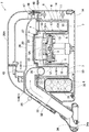
以下、本発明の実施形態について、図1乃至図3に基づいて説明する。同図において、1は卓上型の掃除機本体である。この掃除機本体1の内部には、電動機2と、この電動機2の回転軸に取り付けられたファン3が設けられており、これら電動機2及びファン3とで送風機4が構成されている。また、掃除機本体1のほぼ中央には電動機2を収納する筒状のホルダ5が形成されている。このホルダ5の底壁部7にはホルダ5の内壁と間隔をおいて立設する左右一対の側壁部6が一体形成され、このホルダ5と左右の側壁部6及び底壁部7によって後述する集塵容器11の取付部8を構成している。前記電動機2は、前記ファン3がホルダ5の上面に形成する通気口5Aに臨んで前記掃除機本体1の底面部1Aに固定される。また、ホルダ5と前記側壁部6との間に形成する凹部10には、集塵容器11と、フィルタ12がそれぞれ組み付けられている。前記集塵容器11は前記凹部10と嵌合するように、それぞれが円筒状に形成された内側環状壁13と外側環状壁14及びこれら内・外側環状壁13,14を一体化する底壁面15とから成り、これら内・外側環状壁13,14と底壁面15で囲まれた環状の集塵部16を形成している。また、フィルタ12は、前記集塵容器11の内側環状壁13にほぼ沿うように、逆カップ状に形成されたフィルタケース17の周壁部に形成する開口部18に取り付けられている。なお、フィルタケース17は、内側環状壁13の下端周縁に形成する段部13Aによって該内側環状壁13と僅かな隙間Sを保って着脱自在に装着されている。また、前記内側環状壁13の上面には前記ホルダ5の上面に形成する通気口5Aを覆う有底筒状の径小段部20が形成され、この径小段部20の周面に連通孔21が開口している。また、前記フィルタケース17の上面には前記径小段部20の上面部に形成する環状リブ23と嵌合する位置決め部24が形成され、さらに、前記掃除機本体1にヒンジ25により回動自在に取り付けられた蓋部26には前記位置決め部24と嵌合する位置決め凹部27が形成されている。また、前記蓋部26には把持部26Aが一体形成され、把持部26Aを持って蓋部26を開いた状態ではフィルタケース17と集塵容器11が掃除機本体1から取り外し可能となり、蓋部26を閉じた状態では蓋部26に形成する位置決め凹部27と前記底壁部7とでフィルタケース17及び集塵容器11を挟み付けてこれらフィルタケース17及び集塵容器11が固定される。この時、フィルタケース17と集塵容器11は、フィルタケース17の位置決め部24が集塵容器11の環状リブ23と嵌合し、さらに、その位置決め部24が蓋部26の位置決め凹部27と嵌合して位置決め固定される。また、前記掃除機本体1内には、蓄電池30を収容する電池収納部31が区画形成されるとともに、前記掃除機本体1の先端側には、内部に吸引管32を設けた突出部33が一体的に設けられている。前記吸引管32の下端には、吸込口34aを設けた吸込部34が着脱自在に取り付けられている。また、前記吸引管32の上端には横方向に屈曲した屈曲部35が形成され、この屈曲部35を前記集塵容器11の内・外側環状壁13,14の間、すなわち、集塵部16の内部で開口させている。この吸引管32の上端縁に形成する屈曲部35によって集塵部16の周方向に流れる気流Fを発生させる渦流形成手段を構成している。このように吸引管32を集塵部16の内部に開口させることにより、吸込口34aから吸引管32を経て集塵容器11に至る通風路40が形成される。更に、この通風路40と連通するように、集塵容器11に装着するフィルタ12を経て集塵容器11の径小段部20の周面に形成する連通孔21とホルダ5の上面に形成する通気口5Aを経てホルダ5の内面に吸気路41が形成され、これら通風路40と吸気路41を通って吸込口34aから吸い込んだ空気を掃除機本体1に形成する図示しない排気口から外部に排出する。なお、図中45は把持部26Aに形成するスイッチ、46は蓋部26のロック及びロック解除する操作釦、47は掃除機本体1と蓋部26の間に介在するパッキンである。更に、48は前記操作釦46と一体形成され、掃除機本体1に形成された係止爪48Aと係合するフックである。
【0010】
次に、本実施形態の作用について説明する。まず、操作釦46を操作して蓋部26を開き、掃除機本体1に形成する取付部8に集塵容器11をセットし、さらに、その集塵容器11の内側環状壁13に被せるようにしてフィルタケース17を装着する。この時、フィルタケース17の下端を内側環状壁13の下端周縁に形成する段部13Aと嵌合させることによって、フィルタケース17に装着されたフィルタ12が内側環状壁13と僅かな隙間Sを保って集塵容器11に装着されている。こうして取付部8に集塵容器11とフィルタケース17をセットした後、蓋部26を閉じると、蓋部26は操作釦46と一体に形成されたフック48が掃除機本体1に形成された係止爪48Aに係止してロックされる。これとともに、取付部8にセットした集塵容器11とフィルタケース17は、蓋部26と取付部8の間に挟着されるとともに、フィルタケース17の位置決め部24が集塵容器11の環状リブ23と嵌合し、さらに、その位置決め部24が蓋部26の位置決め凹部27と嵌合して集塵容器11とフィルタケース17が掃除機本体1にぐらつかずに保持される。そして、把持部26Aを握ってスイッチ45を操作することによって送風機4が駆動する。
【0011】
送風機4の駆動により、塵埃を含んだ空気が前記吸込口34aから吸引され、通風路40から吸気路41に至り、掃除機本体1に形成する図示しない排気口から外部に排出される。この時、集塵容器11の集塵部16に臨む吸引管32の上端に屈曲部35が形成されているため、集塵部16内の空気は、屈曲部35に導かれて、集塵容器11の内・外側環状壁13,14に沿って渦流となる。この渦流により、渦流に含まれる塵埃は、遠心力によって集塵容器11の外側環状壁14の内壁に押し付けられるので、比較的重い塵埃はそのまま集塵容器11の外側環状壁14の内周面付近に留まることになり、渦流から分離される。一方、綿埃等の比較的軽い塵埃や細かい塵埃などは、渦流と共に吸気路41側に吸引され、フィルタ12によって捕集される。
【0012】
清掃終了後、操作釦46を操作してフック48と係止爪48Aとのロックを解除して蓋部26を開いた後、フィルタケース17と集塵容器11を取り外す。そして、集塵部16に溜まった塵埃をゴミ箱に捨て、また、フィルタ12に付着した塵埃を除去する。このように、フィルタケース17が集塵容器11に対して着脱自在であることによって、フィルタ12のメンテナンスを容易にできる。
【0013】
以上のように本実施例においては、集塵部16を環状に形成すると共に、前記電動機2及びファン3の外周を囲むように環状の集塵部16を配したことによって、フィルタ12によって濾過された塵埃が集塵部16に溜められると共に、塵埃が除かれた空気が集塵部16で囲まれたファン3によって吸引されて外部に放出される。このように、集塵部16を環状に形成することで塵埃を効率的に収容することができ、塵埃の収容量も多い。また、集塵部16の内周側にフィルタ12を設けたことにより、ファン3の回転によって吸引される塵埃が集塵部16内周側に設けられたフィルタ12によって濾過されると共に、塵埃の除かれた空気が集塵部16内周のフィルタ12を通過して短い経路でファン3に至るから、電動機2及びファン3の周囲に集塵部16をコンパクトに配置することができ、掃除機1の小型化が可能となる。さらに、前記集塵部16の内周側の全周に渡ってフィルタ12を形成したものであるから、ファン3の回転によって形成された気流Fに含まれる塵埃が、集塵部16内周の全周に広く形成されたフィルタ3の全域に渡って濾過され、塵埃を確実に捕集することができる。また、集塵容器11の集塵部16に臨む吸引管32の上端に屈曲部35を形成することにより、前記集塵部16の周方向に流れる気流Fが発生する。これにより、集塵部16内に吸引された塵埃を含む空気が集塵部16外周に沿って回転し、遠心力によって大きな塵埃が集塵部16の外周側内壁に押し付けられて塵埃の一部が気流Fから除かれて分離するとともに、細かな塵埃は吸引され、細かな塵埃のみが集塵部16内周に設けられたフィルタ12によって濾過されるから、フィルタ12の目詰まりを防止することができる。このように、単に吸引管32の上端に屈曲部35を形成することにより、集塵部16の周方向に流れる気流Fを発生させ、目詰まりを防ぐことができるために、フィルタ12に付着した塵埃を落とすための複雑な機構も不要であり、製品のコストアップを招くという虞もない。
【0014】
以上、本発明の実施例について詳述したが、本発明は、前記実施例に限定されるものではなく、本発明の要旨の範囲内で種々の変形実施が可能である。例えば、渦流形成手段としての屈曲部35の形状やフィルタ12の取付構造といった掃除機としての基本的構造は適宜選定すればよい。また、前記実施例では、いわゆる卓上型の掃除機を示したが、これ以外の構造でもよい。
【0015】
【発明の効果】
本発明の請求項1の電気掃除機は、掃除機本体と、この掃除機本体内のほぼ中央に形成され上面に通気口を形成する筒状のホルダに収容された電動機と、この電動機の回転軸に取り付けられて駆動されるファンと、このファンによって吸引された空気に含まれる塵埃を濾過し逆カップ状に形成されたフィルタケースの周壁部に取り付けられているフィルタと、このフィルタによって濾過された塵埃を溜める円筒状に形成された内側環状壁と外側環状壁及びこれら内・外側環状壁を一体化する底壁面とを有し、これら内・外側環状壁と底壁面で囲まれた環状の集塵部を形成する集塵容器と、前記掃除機本体に回動自在に取り付けられた蓋部とを有し、前記集塵部の内周側の全周に渡って前記フィルタを形成し、前記集塵部の周方向に気流が流れるようにするための渦流形成手段を設け、前記蓋部に前記フィルタケースの上面に設けられた位置決め部と嵌合する位置決め凹部が形成されているものであるから、電動機及びファンの外周を囲むように環状の集塵部をコンパクトに配置することができ、電気掃除機の小型化が可能となる。また、フィルタが目詰まりを起こしにく、またファンの回転によって形成された気流に含まれる塵埃が、集塵部内周の全周に広く形成されたフィルタの全域に渡って濾過させることができる。
【0016】
また、本発明の請求項2の電気掃除機によれば、請求項1記載の電気掃除機において、前記フィルタケースは、前記内側環状壁の下端周縁に形成された段部によって、前記内側環状壁と僅かな隙間を保って着脱自在に装着されているものであるから、フィルタケースは、内側環状壁と僅かな隙間を保って装着される。
【図面の簡単な説明】
【図1】本発明の一実施形態を示す掃除機を正面方向から見た断面図である。
【図2】同上、掃除機を側面方向から見た断面図である。
【図3】同上、図2のA−A線断面図である。
【符号の説明】
1 掃除機本体
2 電動機
3 ファン
4 送風機
5 ホルダ
5A 通気口
11 集塵容器
12 フィルタ
13 内側環状壁
13 A 段部
14 外側環状壁
15 底壁面
16 集塵部
17 フィルタケース
24 位置決め部
26 蓋部
27 位置決め凹部
35 屈曲部(渦流形成手段)
S 隙間 [0001]
[Technical field to which the invention belongs]
The present invention relates to a vacuum cleaner, and more particularly to a vacuum cleaner that collects collected dust in a detachable container.
[0002]
[Problems to be solved by the invention]
Conventionally, as this type of vacuum cleaner, for example, the one described in JP-A-5-253096 is known. This is a hand-held vacuum cleaner, and a dust collection case (dust collection part) and filter are provided in front of the fan motor (fan and motor), and dust contained in the air sucked by the fan motor is filtered by the filter. And collected in a dust collection case. A relatively large vacuum cleaner that collects dust based on the same principle is also known from Japanese Patent Laid-Open No. 5-1554075.
[0003]
However, in these vacuum cleaners, the fan motor and the dust collecting case are arranged in the front-rear or top-bottom direction, so that there is a problem that the entire vacuum cleaner is increased in size. And when trying to avoid the size of the vacuum cleaner, if the dust collection case is downsized, the vacuum cleaner can be made relatively small. However, since the amount of dust is reduced, practicality is sacrificed. There was a risk that it would end up. In addition, the former vacuum cleaner has a problem that the filter is likely to be clogged with dust, and in order to prevent this clogging, in order to prevent this clogging, it is necessary to remove dust attached to the filter. It is conceivable to provide a mechanism. However, when such a mechanism is provided, there is a problem that the cost of the product is increased.
[0004]
An object of the present invention is to solve the above-described problems and to provide a vacuum cleaner that can be configured relatively small and is less likely to be clogged.
[0005]
[Means for Solving the Problems]
A vacuum cleaner according to a first aspect of the present invention includes a vacuum cleaner body, an electric motor housed in a cylindrical holder that is formed substantially at the center of the vacuum cleaner body and forms a vent on the upper surface, and the rotation of the electric motor . A fan attached to the shaft and driven, a filter attached to a peripheral wall portion of a filter case formed in a reverse cup shape by filtering dust contained in air sucked by the fan, and filtered by the filter A cylindrical inner wall and an outer annular wall, and a bottom wall surface that integrates these inner and outer annular walls, and an inner ring wall surrounded by the inner and outer annular walls and the bottom wall surface. A dust collecting container that forms a dust collecting portion, and a lid that is rotatably attached to the cleaner body, and forms the filter over the entire circumference of the inner peripheral side of the dust collecting portion, Airflow flows in the circumferential direction of the dust collector The swirl means for so provided, in which positioning recess to be fitted to the positioning portion provided on the upper surface of the filter case to the lid portion.
[0006]
With the configuration according to claim 1, is disposed an annular dust collecting portion so as to surround the outer periphery of the motor and the fan, together with dust is filtered by the filter is collected in the dust collection unit, the dust is removed air It is sucked and discharged to the outside by a fan surrounded by the dust collecting part. In addition, dust contained in the airflow formed by the rotation of the fan is filtered over the entire area of the filter widely formed on the entire inner circumference of the dust collecting section, and the air from which the dust has been removed is Pass through the filter and reach the fan in a short path. In addition, air containing dust sucked into the dust collecting portion rotates along the outer periphery of the dust collecting portion by the vortex forming means, so that a large amount of dust is pressed against the inner peripheral wall of the dust collecting portion by centrifugal force. Part of the dust is removed from the airflow, and dust is removed by a filter provided on the inner periphery of the dust collecting portion.
[0007]
The vacuum cleaner according to
[0008]
With the configuration of the second aspect, the filter case is mounted with a slight gap from the inner annular wall.
[0009]
DETAILED DESCRIPTION OF THE INVENTION
Hereinafter, embodiments of the present invention will be described with reference to FIGS. 1 to 3. In the figure, reference numeral 1 denotes a desktop vacuum cleaner body. Inside the vacuum cleaner main body 1, an
[0010]
Next, the operation of this embodiment will be described. First, the
[0011]
By driving the
[0012]
After the cleaning is completed, the
[0013]
As described above, in the present embodiment, the
[0014]
As mentioned above, although the Example of this invention was explained in full detail, this invention is not limited to the said Example, A various deformation | transformation implementation is possible within the range of the summary of this invention. For example, the basic structure as the vacuum cleaner, such as the shape of the
[0015]
【The invention's effect】
A vacuum cleaner according to a first aspect of the present invention includes a vacuum cleaner body, an electric motor housed in a cylindrical holder that is formed substantially at the center of the vacuum cleaner body and forms a vent on the upper surface, and the rotation of the electric motor . A fan attached to the shaft and driven, a filter attached to a peripheral wall portion of a filter case formed in a reverse cup shape by filtering dust contained in air sucked by the fan, and filtered by the filter A cylindrical inner wall and an outer annular wall, and a bottom wall surface that integrates these inner and outer annular walls, and an inner ring wall surrounded by the inner and outer annular walls and the bottom wall surface. A dust collecting container that forms a dust collecting portion, and a lid that is rotatably attached to the cleaner body, and forms the filter over the entire circumference of the inner peripheral side of the dust collecting portion, Airflow flows in the circumferential direction of the dust collector As the swirl means to provided, said because positioning recess to be fitted to the positioning portion provided on the upper surface of the filter case in which is formed on the lid, so as to surround the outer periphery of the motor and fan An annular dust collecting portion can be arranged in a compact manner, and the vacuum cleaner can be miniaturized. In addition, the filter is less likely to be clogged, and dust contained in the airflow formed by the rotation of the fan can be filtered over the entire area of the filter that is widely formed on the entire inner circumference of the dust collecting portion.
[0016]
According to the vacuum cleaner of
[Brief description of the drawings]
FIG. 1 is a cross-sectional view of a vacuum cleaner as viewed from the front according to an embodiment of the present invention.
FIG. 2 is a cross-sectional view of the vacuum cleaner as viewed from the side.
3 is a cross-sectional view taken along line AA in FIG.
[Explanation of symbols]
1
5 Holder
5A Vent
11 Dust collection container
12 Filter
13 inner ring wall
13 A Step
14 outer annular wall
15 bottom wall
16 Dust collector
17 Filter case
24 Positioning part
26 lid
27 Positioning recess
35 Bent part (vortex forming means)
S clearance
Claims (2)
この掃除機本体内のほぼ中央に形成され上面に通気口を形成する筒状のホルダに収容された電動機と、
この電動機の回転軸に取り付けられて駆動されるファンと、
このファンによって吸引された空気に含まれる塵埃を濾過し逆カップ状に形成されたフィルタケースの周壁部に取り付けられているフィルタと、
このフィルタによって濾過された塵埃を溜める円筒状に形成された内側環状壁と外側環状壁及びこれら内・外側環状壁を一体化する底壁面とを有し、これら内・外側環状壁と底壁面で囲まれた環状の集塵部を形成する集塵容器と、
前記掃除機本体に回動自在に取り付けられた蓋部とを有し、
前記集塵部の内周側の全周に渡って前記フィルタを形成し、
前記集塵部の周方向に気流が流れるようにするための渦流形成手段を設け、
前記蓋部に前記フィルタケースの上面に設けられた位置決め部と嵌合する位置決め凹部が形成されていることを特徴とする電気掃除機。 The vacuum cleaner body ,
An electric motor housed in a cylindrical holder that is formed in the center of the vacuum cleaner body and forms a vent on the upper surface ;
A fan attached to the rotating shaft of the electric motor and driven;
A filter attached to a peripheral wall portion of a filter case formed by filtering the dust contained in the air sucked by the fan and formed in a reverse cup shape ;
A cylindrical inner wall and an outer annular wall for collecting dust filtered by the filter, and a bottom wall surface that integrates the inner and outer annular walls. The inner and outer annular walls and the bottom wall surface A dust collecting container that forms an enclosed annular dust collecting portion;
A lid portion rotatably attached to the vacuum cleaner body,
Forming the filter over the entire circumference on the inner circumference side of the dust collecting part,
A vortex forming means for allowing airflow to flow in the circumferential direction of the dust collecting part is provided,
A vacuum cleaner characterized in that a positioning recess for fitting with a positioning portion provided on an upper surface of the filter case is formed in the lid portion .
Priority Applications (2)
| Application Number | Priority Date | Filing Date | Title |
|---|---|---|---|
| JP2001185125A JP3674031B2 (en) | 2001-06-19 | 2001-06-19 | Vacuum cleaner |
| US10/173,014 US20020189048A1 (en) | 2001-06-18 | 2002-06-18 | Vacuum cleaner |
Applications Claiming Priority (1)
| Application Number | Priority Date | Filing Date | Title |
|---|---|---|---|
| JP2001185125A JP3674031B2 (en) | 2001-06-19 | 2001-06-19 | Vacuum cleaner |
Publications (3)
| Publication Number | Publication Date |
|---|---|
| JP2003000497A JP2003000497A (en) | 2003-01-07 |
| JP2003000497A5 JP2003000497A5 (en) | 2004-08-19 |
| JP3674031B2 true JP3674031B2 (en) | 2005-07-20 |
Family
ID=19024763
Family Applications (1)
| Application Number | Title | Priority Date | Filing Date |
|---|---|---|---|
| JP2001185125A Expired - Fee Related JP3674031B2 (en) | 2001-06-18 | 2001-06-19 | Vacuum cleaner |
Country Status (2)
| Country | Link |
|---|---|
| US (1) | US20020189048A1 (en) |
| JP (1) | JP3674031B2 (en) |
Families Citing this family (43)
| Publication number | Priority date | Publication date | Assignee | Title |
|---|---|---|---|---|
| US7653963B2 (en) | 2002-11-12 | 2010-02-02 | Black & Decker Inc. | AC/DC hand portable wet/dry vacuum having improved portability and convenience |
| SE0300355D0 (en) * | 2003-02-10 | 2003-02-10 | Electrolux Ab | Hand held vacuum cleaner |
| US7152272B2 (en) * | 2003-07-14 | 2006-12-26 | Royal Appliance Mfg. Co. | On-board vehicle vacuum cleaner |
| GB0318284D0 (en) * | 2003-08-05 | 2003-09-10 | Black & Decker Inc | Hand-held vacuum cleaner |
| US20050081321A1 (en) * | 2003-10-15 | 2005-04-21 | Milligan Michael A. | Hand-held cordless vacuum cleaner |
| US8015661B2 (en) * | 2003-12-08 | 2011-09-13 | Shop Vac Corporation | Vacuum with rechargeable battery |
| DE102005007925B4 (en) * | 2005-02-11 | 2006-11-02 | Alfred Kärcher Gmbh & Co. Kg | suction device |
| US7757340B2 (en) | 2005-03-25 | 2010-07-20 | S.C. Johnson & Son, Inc. | Soft-surface remediation device and method of using same |
| DE102005047074A1 (en) * | 2005-09-30 | 2007-04-05 | BSH Bosch und Siemens Hausgeräte GmbH | Vacuum cleaner has vacuum chamber which is partially configured by dust collector which is hermetically sealed relative to surroundings |
| SE0600668L (en) | 2006-03-24 | 2007-10-23 | Electrolux Abp | Handheld vacuum cleaner |
| CN101448447B (en) | 2006-04-10 | 2012-06-27 | 伊莱克斯公司 | Vacuum cleaner with filter cleaning means |
| EP2012638B1 (en) | 2006-04-10 | 2013-06-19 | Aktiebolaget Electrolux | A vacuum cleaner |
| SE531125C2 (en) | 2007-01-19 | 2008-12-23 | Electrolux Ab | Improvements in air flow losses in a vacuum cleaner |
| GB2440108A (en) | 2006-07-18 | 2008-01-23 | Dyson Technology Ltd | Suction cleaner with filter detection mechanism |
| WO2008009887A1 (en) * | 2006-07-18 | 2008-01-24 | Dyson Technology Limited | A handheld cleaning appliance with a cyclone and a pre-motor filter |
| GB2440125A (en) | 2006-07-18 | 2008-01-23 | Dyson Technology Ltd | Cyclonic separating apparatus |
| GB2474176A (en) * | 2006-07-18 | 2011-04-06 | Dyson Technology Ltd | A hand-held vacuum cleaner with handle and suction pipe relatively angled |
| WO2008009890A1 (en) | 2006-07-18 | 2008-01-24 | Dyson Technology Limited | Handheld cleaning appliance |
| US9301666B2 (en) * | 2006-12-12 | 2016-04-05 | Omachron Intellectual Property Inc. | Surface cleaning apparatus |
| US20210401246A1 (en) | 2016-04-11 | 2021-12-30 | Omachron Intellectual Property Inc. | Surface cleaning apparatus |
| WO2008091199A1 (en) | 2007-01-23 | 2008-07-31 | Aktiebolaget Electrolux | Vacuum cleaner nozzle |
| EP2220986B1 (en) * | 2007-02-12 | 2014-03-26 | Black & Decker Inc. | Motor, fan and filter arrangement for a vacuum cleaner |
| DE602007010720D1 (en) * | 2007-02-12 | 2011-01-05 | Black & Decker Inc | vacuum cleaner |
| US9591952B2 (en) | 2009-03-11 | 2017-03-14 | Omachron Intellectual Property Inc. | Hand vacuum cleaner with removable dirt chamber |
| US10722086B2 (en) | 2017-07-06 | 2020-07-28 | Omachron Intellectual Property Inc. | Handheld surface cleaning apparatus |
| EP2581012B1 (en) * | 2011-10-12 | 2015-01-21 | Black & Decker Inc. | A motor, fan and cyclonic separation apparatus arrangement for a vacuum cleaner |
| EP2581022B1 (en) * | 2011-10-12 | 2014-05-21 | Black & Decker Inc. | A motor, fan and cyclonic seperation apparatus arrangement |
| GB2499240B (en) | 2012-02-10 | 2014-08-20 | Dyson Technology Ltd | Vacuum cleaner |
| EP3003109B1 (en) * | 2013-06-05 | 2019-10-02 | Grey Technology Limited | Hand-held vacuum cleaner |
| US9107550B2 (en) | 2013-09-27 | 2015-08-18 | Black & Decker Inc. | Compact vacuum and sander |
| WO2017171496A1 (en) | 2016-03-31 | 2017-10-05 | 엘지전자 주식회사 | Cleaning apparatus |
| WO2017171495A1 (en) | 2016-03-31 | 2017-10-05 | 엘지전자 주식회사 | Cleaning apparatus |
| KR102560970B1 (en) * | 2016-03-31 | 2023-07-31 | 엘지전자 주식회사 | Cleaner |
| US11166607B2 (en) | 2016-03-31 | 2021-11-09 | Lg Electronics Inc. | Cleaner |
| AU2017240615B2 (en) * | 2016-03-31 | 2019-12-05 | Lg Electronics Inc. | Cleaning apparatus |
| US11918170B2 (en) | 2016-04-11 | 2024-03-05 | Omachron Intellectual Property Inc. | Surface cleaning apparatus |
| CA2971068A1 (en) * | 2016-06-30 | 2017-12-30 | Jiangsu Midea Cleaning Appliances Co., Ltd. | Handheld vacuum cleaner |
| JP1579985S (en) * | 2016-08-26 | 2017-06-26 | ||
| EP3381343A1 (en) * | 2017-03-27 | 2018-10-03 | Koninklijke Philips N.V. | Battery-operated vacuum cleaner |
| US11358156B1 (en) * | 2019-05-10 | 2022-06-14 | Vacuum Technologies, Llc | Dual connection cyclonic overhead separator |
| WO2021262952A1 (en) * | 2020-06-24 | 2021-12-30 | Milwaukee Electric Tool Corporation | Vacuum cleaner with liquid retention |
| CN114682601A (en) * | 2020-12-28 | 2022-07-01 | 新沂市恒盛石英制品厂 | Be used for broken quartz sand dust collection device |
| WO2022174586A1 (en) * | 2021-02-22 | 2022-08-25 | 追觅创新科技(苏州)有限公司 | Handheld vacuum cleaner |
Family Cites Families (6)
| Publication number | Priority date | Publication date | Assignee | Title |
|---|---|---|---|---|
| US2049603A (en) * | 1929-11-29 | 1936-08-04 | Electrolux Corp | Pneumatic cleaner |
| US1861261A (en) * | 1930-01-25 | 1932-05-31 | Electric Vacuum Cleaner Co | Hand vacuum cleaner |
| US2778441A (en) * | 1953-12-21 | 1957-01-22 | James R Herriott | Bed deodorizers |
| US5319828A (en) * | 1992-11-04 | 1994-06-14 | Tennant Company | Low profile scrubber |
| US5536637A (en) * | 1993-04-07 | 1996-07-16 | Genetics Institute, Inc. | Method of screening for cDNA encoding novel secreted mammalian proteins in yeast |
| US6488744B2 (en) * | 2001-03-19 | 2002-12-03 | Hmi Industries, Inc. | Filter system |
-
2001
- 2001-06-19 JP JP2001185125A patent/JP3674031B2/en not_active Expired - Fee Related
-
2002
- 2002-06-18 US US10/173,014 patent/US20020189048A1/en not_active Abandoned
Also Published As
| Publication number | Publication date |
|---|---|
| US20020189048A1 (en) | 2002-12-19 |
| JP2003000497A (en) | 2003-01-07 |
Similar Documents
| Publication | Publication Date | Title |
|---|---|---|
| JP3674031B2 (en) | Vacuum cleaner | |
| JP2003000497A5 (en) | ||
| JP3442351B2 (en) | Electric vacuum cleaner | |
| US5935279A (en) | Removable cyclone separator for a vacuum cleaner | |
| JP3930737B2 (en) | Multiple cyclone vacuum cleaner | |
| JP4241493B2 (en) | Dust collector for vacuum cleaner | |
| AU2006203113A1 (en) | Hand-holdable vacuum cleaners | |
| JP2004113760A (en) | Wet and dry type cleaner | |
| ITRM20000006A1 (en) | CYCLONIC EFFECT DIRT CONTAINER COMPLEX. | |
| JP5659641B2 (en) | Electric vacuum cleaner | |
| JP5598169B2 (en) | Dust collector and vacuum cleaner | |
| JP3667219B2 (en) | Vacuum cleaner | |
| KR100414808B1 (en) | Vacuum cleaner | |
| JP2004154483A (en) | Dust collecting device and vacuum cleaner using the same | |
| JP2003290096A (en) | Cyclone type vacuum cleaner | |
| JP3926582B2 (en) | Dust collection case and vacuum cleaner | |
| JP6491779B2 (en) | Dust collector and vacuum cleaner | |
| JP2004305230A (en) | Vacuum cleaner | |
| JP2007167450A (en) | Cyclone type vacuum cleaner | |
| JP2004089263A (en) | Vacuum cleaner | |
| JPH01305917A (en) | Electric cleaner | |
| JP2006061540A (en) | Vacuum cleaner | |
| JP4453488B2 (en) | Vacuum cleaner | |
| JP4000521B2 (en) | Electric vacuum cleaner | |
| JPS6237552Y2 (en) |
Legal Events
| Date | Code | Title | Description |
|---|---|---|---|
| A521 | Request for written amendment filed |
Free format text: JAPANESE INTERMEDIATE CODE: A523 Effective date: 20030801 |
|
| A621 | Written request for application examination |
Free format text: JAPANESE INTERMEDIATE CODE: A621 Effective date: 20030801 |
|
| A521 | Request for written amendment filed |
Free format text: JAPANESE INTERMEDIATE CODE: A523 Effective date: 20030804 |
|
| A977 | Report on retrieval |
Free format text: JAPANESE INTERMEDIATE CODE: A971007 Effective date: 20041109 |
|
| A131 | Notification of reasons for refusal |
Free format text: JAPANESE INTERMEDIATE CODE: A131 Effective date: 20041116 |
|
| A521 | Request for written amendment filed |
Free format text: JAPANESE INTERMEDIATE CODE: A523 Effective date: 20050117 |
|
| TRDD | Decision of grant or rejection written | ||
| A01 | Written decision to grant a patent or to grant a registration (utility model) |
Free format text: JAPANESE INTERMEDIATE CODE: A01 Effective date: 20050404 |
|
| A61 | First payment of annual fees (during grant procedure) |
Free format text: JAPANESE INTERMEDIATE CODE: A61 Effective date: 20050417 |
|
| R150 | Certificate of patent or registration of utility model |
Free format text: JAPANESE INTERMEDIATE CODE: R150 |
|
| FPAY | Renewal fee payment (event date is renewal date of database) |
Free format text: PAYMENT UNTIL: 20080513 Year of fee payment: 3 |
|
| FPAY | Renewal fee payment (event date is renewal date of database) |
Free format text: PAYMENT UNTIL: 20090513 Year of fee payment: 4 |
|
| FPAY | Renewal fee payment (event date is renewal date of database) |
Free format text: PAYMENT UNTIL: 20100513 Year of fee payment: 5 |
|
| FPAY | Renewal fee payment (event date is renewal date of database) |
Free format text: PAYMENT UNTIL: 20100513 Year of fee payment: 5 |
|
| FPAY | Renewal fee payment (event date is renewal date of database) |
Free format text: PAYMENT UNTIL: 20110513 Year of fee payment: 6 |
|
| FPAY | Renewal fee payment (event date is renewal date of database) |
Free format text: PAYMENT UNTIL: 20110513 Year of fee payment: 6 |
|
| FPAY | Renewal fee payment (event date is renewal date of database) |
Free format text: PAYMENT UNTIL: 20120513 Year of fee payment: 7 |
|
| FPAY | Renewal fee payment (event date is renewal date of database) |
Free format text: PAYMENT UNTIL: 20120513 Year of fee payment: 7 |
|
| FPAY | Renewal fee payment (event date is renewal date of database) |
Free format text: PAYMENT UNTIL: 20130513 Year of fee payment: 8 |
|
| FPAY | Renewal fee payment (event date is renewal date of database) |
Free format text: PAYMENT UNTIL: 20140513 Year of fee payment: 9 |
|
| R250 | Receipt of annual fees |
Free format text: JAPANESE INTERMEDIATE CODE: R250 |
|
| R250 | Receipt of annual fees |
Free format text: JAPANESE INTERMEDIATE CODE: R250 |
|
| LAPS | Cancellation because of no payment of annual fees |