JP3673741B2 - Long object moving displacement measuring method and apparatus for carrying out this method - Google Patents
Long object moving displacement measuring method and apparatus for carrying out this method Download PDFInfo
- Publication number
- JP3673741B2 JP3673741B2 JP2001268277A JP2001268277A JP3673741B2 JP 3673741 B2 JP3673741 B2 JP 3673741B2 JP 2001268277 A JP2001268277 A JP 2001268277A JP 2001268277 A JP2001268277 A JP 2001268277A JP 3673741 B2 JP3673741 B2 JP 3673741B2
- Authority
- JP
- Japan
- Prior art keywords
- target
- index
- long object
- side target
- long
- Prior art date
- Legal status (The legal status is an assumption and is not a legal conclusion. Google has not performed a legal analysis and makes no representation as to the accuracy of the status listed.)
- Expired - Lifetime
Links
Images


Description
【0001】
【発明の属する技術分野】
この発明は、長尺物体移動変位量測定方法およびこの方法を実施する装置に関し、特に、鉄道線路のレールの如き移動変位する長尺物体の移動変位量を写真画像に基づいて測定検査する長尺物体移動変位量測定方法およびこの方法を実施する装置に関する。
【0002】
【従来の技術】
従来例を図8を参照して説明する。以下、鉄道線路のレールを移動変位する長尺物体の一例として説明する。
左右のレール1とまくらぎ2の相互間は締結部材により強固に結合されているが、この締結力が小さく道床縦抵抗力も小さい場合、走行する列車の制動、始動荷重およびレール1の温度変化に起因する伸縮その他に起因してレール1が長手方向に移動することがある。このレール1の長手方向の移動を一般にふく進と呼んでいる。ふく進量が大きい場合、レール1を適正位置に引き戻す作業を実施する必要があり、鉄道各社は年に2回程ふく進量の測定を実施している。
【0003】
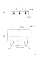
ふく進量を測定するは、図8に示される如く、左右のレール1それぞれの外側に基準器3を設置し、両基準器3の標点32間に糸を張ってこれを基準線4とすると共に、左右のレール1それぞれの基準線4に対応するところに基準点5を設置しておく。レール1に設置した基準点5と基準線4との間の距離を作業員が現場でスケールを使用して目視により測定する。ふく進する側であるレール1の基準点5は、ロングレール軌道の場合、不動区間において150m〜200m間隔で設置される。
【0004】
【発明が解決しようとする課題】
以上のふく進量の測定は、作業員がが現場に立ち入って目視により実施するものであり、検査箇所も150mないし200m間隔で1箇所という膨大なものである。そして、測定作業は、日中の非常に短い列車走行時間間隔の合間に行われなければならないし、見通し不良区間において線路上を横断或いは移動しながら測定を行なわなければならない場合もあり、作業員には常に列車触車事故の危険が伴う。従って、鉄道線路内に立ち入らずにふく進量の測定を実施することができるレールの移動変位量測定装置の開発が要請されている。また、ふく進量の測定には、列車見張員を含めて、通常6人程度の多くの人員を必要としており、この必要作業員数の削減も要請されている。更に、測定の精度については、現場における作業員の目視による測定であるところから、測定時の誤差は±5mm程度あると考えられている。また、糸を張ってこれを基準線4としてふく進量を測定するので、強風その他の測定環境条件に災いされて基準線4がたわみ、測定が困難になり、或いは測定の正確性が低下する恐れがある。この様な測定環境条件に左右されることなく、測定精度を維持することができる移動変位量測定装置の開発も要請されている。
【0005】
この発明は、移動変位する長尺物体の移動変位量を写真画像に基づいて測定検査することにより上述の問題を解消した長尺物体移動変位量測定方法およびこの方法を実施する装置を提供するものである。
【0006】
【課題を解決するための手段】
請求項1:長尺物体に物体側ターゲット34を形成し、長尺物体の近傍に1対の不動ターゲット33を設け、両不動ターゲット33に付与形成される指標35間を結んだ直線を基準線4とし、これらの写真画像を撮像して、物体側ターゲット34に付与形成される指標35の基準線4を基準としたずれ量を写真画像上において座標演算処理して求め、長尺物体の移動量を測定する長尺物体移動変位量測定方法において、
不動ターゲット33および物体側ターゲット34には3個以上の指標35を等間隔に共通して付与形成し、
各物体側ターゲット34の指標35の基準線4を基準としたずれ量を3個以上求めてこれらを平均して得られた値を長尺物体移動変位量とする長尺物体移動変位量測定方法を構成した。
そして、請求項2:長尺物体に形成される物体側ターゲット34と長尺物体の近傍に固定される1対の基準器のそれぞれに形成される不動ターゲット33を具備し、
不動ターゲット33および物体側ターゲット34には3個以上の複数個の指標35を等間隔に共通して付与形成し、
1対の基準器の不動ターゲット33の指標35および物体側ターゲット34の指標35を横方向および高さ方向共に一直線状に配列位置決めし、
1対の基準器の不動ターゲット33の指標35および物体側ターゲット34の指標35の写真画像を撮像するカメラ6を具備し、
写真画像における両不動ターゲット33に付与形成される指標35間を結んだ基準線4を基準とする物体側ターゲット34の指標35のずれ量を写真画像上において座標演算処理して求めるCPUを含む演算処理装置を具備し、
長尺物体の移動変位量を測定する長尺物体移動変位量測定装置を構成した。
【0007】
ここで、請求項3:請求項2に記載される長尺物体移動変位量測定装置において、不動ターゲット33および物体側ターゲット34に付与形成する指標35の個数を3とした長尺物体移動変位量測定装置を構成した。
【0008】
【発明の実施の形態】
この発明の実施の形態を実施例を参照して説明する。この発明の実施例も、鉄道線路のレールを移動変位する長尺物体の一例として説明する。
図1および図2を参照するに、この発明は、移動変位する長尺物体である鉄道線路のレール1の両側に固定して形成される不動ターゲット33と、レール1に形成した物体側ターゲット34とを撮影し、不動ターゲット33と物体側ターゲット34相互位置関係を解析することにより移動変位量を算出するものである。
【0009】
不動ターゲット33および物体側ターゲット34には、撮影した写真上で正確にその形成位置を判別する指標35が付与される。指標35の形状は円形とし、写真上で円の中心を認識させて、写真上で指標35の座標位置の読み取りをでき得る限り正確にさせる。
物体側ターゲット34は、長尺物体であるレール1の1個について1枚だけ形成され、このレール1の移動量を測定するのに2箇所に不動ターゲット33を形成する。移動量を求めるには、不動ターゲット33および物体側ターゲット34の双方に1枚につき2点以上の指標35を付与する構成とする。指標35間の実際の長さDは既知とし、移動長尺物体であるレール1に固定された物体側ターゲット34の各指標35間の長さDが実際の移動量を算出する際の基準スケールとなる。
【0010】
これについて概略を説明するに、物体側ターゲット34を形成したレール1の両側に不動ターゲット33を形成した場合、両不動ターゲット33の指標35間を直線で結んだ線が基準線4となり、物体側ターゲット34の指標35が基準線4上に並んでいる場合はレール1の移動量は0であるものとする。レール1が移動変位した場合に撮影した写真は、基準線4とレール1に固定された物体側ターゲット34の指標35との間の最短距離を写真画面上の座標から算出し、基準スケールDの長さにより実際の距離に変換し、レール1の移動量を求める。
【0011】
ここで、図3を参照するに、1枚のターゲット33(34)の指標35の数について、指標35が図3(a)に示される1点の場合、基準線4を参照してレール1が移動したことを判別することはできるが、基準スケールDを形成することができないので移動量を求めることはできない。指標35が図3(b)に示され2点の場合、基準スケールDが1個だけできて、このスケールDにより移動量を求めることができる。しかし、これらのターゲットが完全に正面から撮影された写真ではない場合、写真画像の基準線4に対する左右の指標35間の距離の比に差異が発生するところから、基準線4に対して左右のスケールが異なることとなり、撮影位置が厳密に設定されない限り、基準線4を基準として正確に移動量を求めることができない。指標が図3(c)に示される3点の場合、図3(b)の2点の場合とは異なり、写真画像における左右部分のスケールの比を各点間の長さから求めることができ、基準線に対する撮影角度の差異の影響を補正することができる。即ち、不動ターゲット33および物体側ターゲット34には3個以上の指標35が等間隔に共通して付与形成される。指標の数が多いことで、指標の中心座標の認識作業、撮影時の手ぶれ、ぼけ、レンズの歪みその他の原因による測定誤差はより軽減される。
【0012】
鉄道のレール1のふく進を求めるには、左右のレール上に形成された各1箇所の物体側ターゲット34と左右のレール1の外側に形成された各1箇所の不動ターゲット33の計4箇所のターゲットを同時にカメラ6で撮影し、撮影した写真画像をCPUを含む演算処理装置で演算処理することにより、レール1の長手方向の移動量と向きを算出し、ふく進量を求める。ここで、不動ターゲット33の形成の仕方により、基準線4の方向を自由に設定することができ、これにより、或る程度移動量と移動方向が決められた、レール1以外の移動物の移動変位量を測定することができる。
【0013】
この発明の実施例を、同様に図1および図2の実施例を参照して、更に具体的に説明する。
ふく進量を測定するに使用される基準器3は、杭31により不動点である設置場所に固定され、不動状態を維持する。32は標点を示す。不動ターゲット33には、間隔Dで円形の指標35が3個付与されている。間隔Dは既知の等間隔に設定され、各指標35の直径は撮影距離により調整される。例えば、不動ターゲット33に到る撮影距離が1000mm程度なら5mm、3000mm程度なら8mmと、撮影距離が大きくなるにつれて直径を大きくする。
【0014】
検査場所1箇所について、基準器3を2個と、2枚の不動ターゲット33と、2枚の物体側ターゲット34を必要とする。遠側基準器3REは、撮影位置から2000mm以内において、遠側レール1REの外側に1000mmだけ離隔して基準器3REの面を遠側レール1REに平行にして固定される。近側基準器3NEは近側レール1NEの外側に1000mmだけ離隔して近側基準器3NEの面を近側レール1REに平行にして固定される。遠側基準器3REと近側基準器3NEの間には糸張りにより基準器面に垂直な基準線4が形成される。そして、遠側レール1REおよび近側レール1NEのカメラ6に対向する側面、遠側基準器3REおよび近側基準器3NEのカメラ6に対向する側面にターゲット33を貼り付け固定する。これに際して、ターゲット33は横方向、高さ方向共に一直線状に配列する必要がある。この形成状態をふく進量0の状態とする。
【0015】
図1(c)を参照してターゲットの撮影の仕方を説明するに、ターゲット33が貼られた基準器面側からカメラ6で4枚のターゲット33が1枚の写真の中に明確に納める撮影をする。
図4、図5および図6を参照してふく進量解析の仕方を説明する。図4は演算処理装置のディスプレイに表示した写真画像を示す図であり、図5は図4の表示画面の座標を説明する図である。演算処理装置のディスプレイに表示した写真画像の縦横の長さをドットで表現するX−Y座標系とし、縦横の中点を結んで交差した中心点を(0、0)とする。
【0016】
写真画像中の4枚のターゲット33(34)中にある各3個の指標35の合計12指標の座標(イ〜ヲ)を写真上から探し、撮影されている各指標35の内の最も中心に位置するドットを各指標35の座標位置として登録する。
登録した指標35の指標座標を基準にしてふく進量を計算する。ここで、遠側レール1REのふく進量の計算の仕方を説明する。
各指標座標位置の内の、ふく進量0mmに相当する基準線4となる遠側基準器3REおよび近側基準器3NE上の対応する指標座標イと指標座標ヌとを結んだ直線式La 、指標座標ロと指標座標ルとを結んだ直線式Lb 、指標座標ハと指標座標オとを結んだ直線式Lc を求める。
【0017】
図6に示される如くレール1RE上の指標座標ニ、ホ、ヘから最小自乗法により直線近似式Raを求める。
直線La 、Lb 、Lc と直線Ra の交点の座標を求め、交点座標A1 、A2 、A3 とする。指標座標ニ、ホ、ヘに最も近い直線Ra 上の座標をニ'、ホ'、ヘ'とする。
直線Ra 上にある座標A1 −座標ニ'間、座標A2 −座標ホ'間、座標A3 −座標ヘ'間の座標間距離を求め、それぞれf1 、f2 、f3 とする。
【0018】
交点座標A1 −交点座標A2 間、交点座標A2 −交点座標A3 間の座標間距離をそれぞれda 、db とする。
実際の指標間距離をDとし、f1 、f2 、f3 の実際の距離c1 、c2 、c3 を次のように求める。
c1 =f1 ×(D/da )
c2 =f2 ×((D/da )+(D/db ))/2
c3 =f3 ×(D/db )
更に、これらの平均値をふく進量Cとする。
【0019】
C=(c1 +c2 +c3 )/3
同様に、近側レールのふく進量を求める。ここで、レール以外の移動物に対しても不動点を2箇所設置し、同様に移動物にターゲットを形成すれば、移動量を求めることができる。そして、図7の如く不動点を設置した場合でも、不動点の延長線上を基準線とすることで移動量を求めることができる。移動物の片側にしか不動点を設置できない場合においても移動量を測定することができる。移動物として、地盤、岩盤、亀裂を対象とすることができ、これらの移動量、移動方向を測定することができる。
【0020】
【発明の効果】
以上の通りであって、この発明によれば、ふく進測定作業を実施するに、線路或は地盤、岩盤、亀裂の如き測定対象に立ち入って様々な器具を持ち込む必要もなければ、測定対象から離隔して、一人でふく進測定作業を実施することができる。そして、ふく進測定作業が従来例と比較して短時間で実施することができ、風その他の外部環境により影響されることなく、また、測定技術に関係なしに従来例と比較して高精度の測定を実施することができる。更に、撮影した写真を保管しておくことができるので、後日に測定結果の再確認をすることができ、測定ミスの対処に役立つ。
具体的には、長尺物体に物体側ターゲット34を形成し、長尺物体の近傍に1対の不動ターゲット33を設け、両不動ターゲット33に付与形成される指標35間を結んだ直線を基準線4とし、これらの写真画像を撮像して、物体側ターゲット34に付与形成される指標35の基準線4を基準としたずれ量を写真画像上において座標演算処理して求め、長尺物体の移動量を測定する長尺物体移動変位量測定方法およびこの方法を実施する装置において、不動ターゲット33および物体側ターゲット34には3個以上の指標35を等間隔に共通して付与形成し、各物体側ターゲット34の指標35の基準線4を基準としたずれ量を3個以上求めてこれらを平均して得られた値を長尺物体移動変位量とする構成を採用した。以上の通り、指標が3点の場合、2点の場合とは異なり、写真画像における左右部分のスケールの比を各点間の長さから求めることができ、基準線に対する撮影角度の差異の影響を補正することができる。指標の数が多いことで、指標の中心座標の認識作業、撮影時の手ぶれ、ぼけ、レンズの歪みその他の原因による測定誤差はより軽減される。
【図面の簡単な説明】
【図1】実施例を説明する図。
【図2】基準器を説明する図。
【図3】ターゲットの指標の数について説明する図。
【図4】演算処理装置のディスプレイに表示した写真画像を示す図。
【図5】表示画面の座標を示す図。
【図6】直線近似式の求め方を説明する図。
【図7】一般的な長尺物体の移動変位量の測定を説明する図。
【図8】従来例を説明する図。
【符号の説明】
1 レール 1’長尺物体
1NE 近側レール 1RE 遠側レール
2 まくらぎ 3 基準器
3NE 近側基準器 3RE 遠側基準器
31 杭32 32 標点
33 不動ターゲット 33’不動ターゲット貼り付け部
34 物体側ターゲット 35 指標
4 基準線 5 基準点
6 カメラ[0001]
BACKGROUND OF THE INVENTION
The present invention relates to a long object moving displacement measuring method and an apparatus for carrying out the method, and more particularly, a long object for measuring and inspecting a moving displacement amount of a long object such as a rail of a railroad track based on a photographic image. The present invention relates to a method for measuring an amount of displacement of an object and an apparatus for performing the method.
[0002]
[Prior art]
A conventional example will be described with reference to FIG. Hereinafter, it demonstrates as an example of the elongate object which moves and displaces the rail of a railroad track.
The left and
[0003]
As shown in FIG. 8, the
[0004]
[Problems to be solved by the invention]
The above measurement of the amount of advancement is carried out by a worker entering the site and visually, and the inspection location is a huge one with 150 to 200 m intervals. And the measurement work must be performed between very short train travel time intervals during the day, and sometimes it is necessary to perform the measurement while crossing or moving on the track in the poor visibility section. Is always accompanied by the danger of a train trolley accident. Therefore, there is a demand for the development of a moving displacement measuring device for rails that can measure the travel amount without entering the railway track. In addition, the travel amount measurement usually requires a large number of personnel, including train guards, of about six people, and a reduction in the required number of workers is also required. Furthermore, with respect to the accuracy of measurement, it is considered that an error during measurement is about ± 5 mm because it is a measurement by visual observation by an operator on site. Further, since the amount of advancement is measured using a yarn as a
[0005]
The present invention provides a long object moving displacement measuring method and an apparatus for carrying out this method, which solves the above-mentioned problems by measuring and inspecting the moving displacement of a long object to be moved and displaced based on a photographic image. It is.
[0006]
[Means for Solving the Problems]
Claim 1: An object-
The
A long object movement displacement measuring method in which three or more deviation amounts with respect to the
And the second aspect of the present invention comprises an object-
The
The
A camera 6 for capturing a photographic image of the
A calculation including a CPU for obtaining a deviation amount of the
A long object moving displacement measuring device for measuring the moving displacement of a long object was constructed.
[0007]
According to a third aspect of the present invention, in the long object movement displacement amount measuring apparatus according to the second aspect, the long object movement displacement amount in which the number of
[0008]
DETAILED DESCRIPTION OF THE INVENTION
Embodiments of the present invention will be described with reference to examples. The embodiment of the present invention will also be described as an example of a long object that moves and displaces a rail of a railway track.
Referring to FIG. 1 and FIG. 2, the present invention relates to a
[0009]
The
Only one object-
[0010]
In order to explain the outline, when the
[0011]
Here, referring to FIG. 3, with respect to the number of
[0012]
In order to determine the travel of the
[0013]
The embodiment of the present invention will be described more specifically with reference to the embodiment of FIG. 1 and FIG.
The
[0014]
Two
[0015]
To describe how to shoot a target with reference to FIG. 1 (c), a shoot in which four
A method for analyzing the amount of advance will be described with reference to FIGS. 4, 5, and 6. FIG. 4 is a diagram showing a photographic image displayed on the display of the arithmetic processing unit, and FIG. 5 is a diagram for explaining the coordinates of the display screen of FIG. An XY coordinate system that expresses the vertical and horizontal lengths of the photographic image displayed on the display of the arithmetic processing unit with dots is assumed to be a center point that intersects the vertical and horizontal midpoints and is (0, 0).
[0016]
The coordinates (i to wo) of a total of 12 indices of each of the three
The advance amount is calculated based on the index coordinates of the registered
Of each index coordinate position, a linear expression that connects the corresponding index coordinate a and the index coordinate n on the far
[0017]
As shown in FIG. 6, a linear approximation Ra is obtained from the index coordinates D, E, F on the
Straight line La , Lb , Lc And straight line Ra The coordinates of the intersection points are obtained, and the intersection point coordinates A 1 , A 2 , A 3 are obtained. Straight line Ra closest to index coordinates d, e, h Let the upper coordinates be d ', ho', f '.
Straight line Ra The inter-coordinate distances between the coordinates A 1 -coordinate d ', the coordinates A 2 -coordinate e', and the coordinates A 3 -coordinate f 'are obtained and are set as f 1 , f 2 , and f 3 , respectively.
[0018]
The distances between the coordinates between the intersection coordinates A 1 and the intersection coordinates A 2 and between the intersection coordinates A 2 and the intersection coordinates A 3 are indicated by da. , Db And
The actual distance between indexes is set to D, and the actual distances c 1 , c 2 , and c 3 of f 1 , f 2 , and f 3 are obtained as follows.
c 1 = f 1 × (D / da )
c 2 = f 2 × ((D / da ) + (D / db )) / 2
c 3 = f 3 × (D / db )
Further, the average value of these values is defined as the advance amount C.
[0019]
C = (c 1 + c 2 + c 3 ) / 3
Similarly, the advance amount of the near rail is obtained. Here, if two fixed points are also installed on a moving object other than the rail and a target is similarly formed on the moving object, the amount of movement can be obtained. Even when a fixed point is installed as shown in FIG. 7, the amount of movement can be obtained by using the extension line of the fixed point as a reference line. Even when the fixed point can be set only on one side of the moving object, the moving amount can be measured. The moving object can be the ground, rock, and crack, and the amount and direction of movement can be measured.
[0020]
【The invention's effect】
As described above, according to the present invention, it is not necessary to enter the measuring object such as the track or the ground, the rock, and the crack to carry out the forward measuring work, Advancing measurement work can be carried out by one person at a distance. In addition, the forward measurement work can be carried out in a short time compared to the conventional example, and it is not affected by the wind or other external environment, and is more accurate than the conventional example regardless of the measurement technique. Measurement can be carried out. Furthermore, since the photographed photo can be stored, the measurement result can be reconfirmed at a later date, which is useful for dealing with measurement errors.
Specifically, an object-
[Brief description of the drawings]
FIG. 1 is a diagram illustrating an embodiment.
FIG. 2 is a diagram illustrating a reference device.
FIG. 3 is a diagram illustrating the number of target indices.
FIG. 4 is a view showing a photographic image displayed on the display of the arithmetic processing unit.
FIG. 5 is a diagram showing coordinates on a display screen.
FIG. 6 is a diagram for explaining how to obtain a linear approximation expression;
FIG. 7 is a diagram for explaining measurement of a moving displacement amount of a general long object.
FIG. 8 illustrates a conventional example.
[Explanation of symbols]
1 rail 1 '
Claims (3)
不動ターゲットおよび物体側ターゲットには3個以上の指標を等間隔に共通して付与形成し、
各物体側ターゲットの指標の基準線を基準としたずれ量を3個以上求めてこれらを平均して得られた値を長尺物体移動変位量とすることを特徴とする長尺物体移動変位量測定方法。An object-side target is formed on a long object, a pair of non-moving targets is provided near the long object, and a straight line connecting the indexes formed on both non-moving targets is used as a reference line to capture these photographic images. A long object moving displacement measuring method for measuring a moving amount of a long object by calculating a displacement amount with reference to a reference line of an index formed on the object side target by performing coordinate arithmetic processing on a photographic image In
The fixed target and the object-side target are formed with three or more indices in common at equal intervals.
A long object movement displacement amount obtained by obtaining three or more deviation amounts with reference to the reference line of the index of each object side target and averaging them to obtain a long object movement displacement amount Measuring method.
1対の基準器の不動ターゲットの指標および物体側ターゲットの指標を横方向および高さ方向共に一直線状に配列位置決めし、
1対の基準器の不動ターゲットの指標および物体側ターゲットの指標の写真画像を撮像するカメラを具備し、
写真画像における両不動ターゲットに付与形成される指標間を結んだ基準線を基準とする物体側ターゲットの指標のずれ量を写真画像上において座標演算処理して求めるCPUを含む演算処理装置を具備し、
長尺物体の移動変位量を測定することを特徴とする長尺物体移動変位量測定装置。A stationary target formed on each of an object-side target formed on a long object and a pair of reference devices fixed in the vicinity of the long object is provided, and the stationary target and the object-side target include three or more A common index is formed at regular intervals,
The index and the index of the object side target immobile target of a pair of the datum line shape are arranged laterally positioned and height directions both,
A camera that captures a photographic image of an index of a stationary target of a pair of reference units and an index of an object side target;
An arithmetic processing unit including a CPU that obtains a deviation amount of an index of an object-side target on the basis of a reference line connecting the indices formed and formed on both immovable targets in a photographic image by performing coordinate arithmetic processing on the photographic image; ,
A long object moving displacement measuring apparatus for measuring a moving displacement of a long object.
不動ターゲットおよび物体側ターゲットに付与形成する指標の個数を3としたことを特徴とする長尺物体移動変位量測定装置。In the long object movement displacement measuring device according to claim 2,
3. A long-object moving displacement measuring apparatus characterized in that the number of indices provided and formed on a stationary target and an object-side target is set to 3.
Priority Applications (1)
| Application Number | Priority Date | Filing Date | Title |
|---|---|---|---|
| JP2001268277A JP3673741B2 (en) | 2001-09-05 | 2001-09-05 | Long object moving displacement measuring method and apparatus for carrying out this method |
Applications Claiming Priority (1)
| Application Number | Priority Date | Filing Date | Title |
|---|---|---|---|
| JP2001268277A JP3673741B2 (en) | 2001-09-05 | 2001-09-05 | Long object moving displacement measuring method and apparatus for carrying out this method |
Publications (2)
| Publication Number | Publication Date |
|---|---|
| JP2003075116A JP2003075116A (en) | 2003-03-12 |
| JP3673741B2 true JP3673741B2 (en) | 2005-07-20 |
Family
ID=19094285
Family Applications (1)
| Application Number | Title | Priority Date | Filing Date |
|---|---|---|---|
| JP2001268277A Expired - Lifetime JP3673741B2 (en) | 2001-09-05 | 2001-09-05 | Long object moving displacement measuring method and apparatus for carrying out this method |
Country Status (1)
| Country | Link |
|---|---|
| JP (1) | JP3673741B2 (en) |
Cited By (1)
| Publication number | Priority date | Publication date | Assignee | Title |
|---|---|---|---|---|
| CN105507100A (en) * | 2016-01-08 | 2016-04-20 | 中铁第四勘察设计院集团有限公司 | Device and method for monitoring basic rail expansion amount of ballast track rail telescopic adjuster |
Families Citing this family (10)
| Publication number | Priority date | Publication date | Assignee | Title |
|---|---|---|---|---|
| JP4660169B2 (en) * | 2004-11-19 | 2011-03-30 | 株式会社キクテック | Rail printing method and equipment |
| JP2007139596A (en) * | 2005-11-18 | 2007-06-07 | Toshiba Corp | Transportable motion measuring system and motion measuring method |
| JP4928130B2 (en) * | 2006-02-08 | 2012-05-09 | 株式会社 ソキア・トプコン | Propeller position measurement system |
| JP5108392B2 (en) * | 2007-06-15 | 2012-12-26 | 株式会社コスモプラニング | Orbital displacement measurement system |
| JP5179995B2 (en) * | 2008-08-07 | 2013-04-10 | 株式会社ニシヤマ | Method and apparatus for measuring track dimensions of track rail |
| JP2011069797A (en) * | 2009-09-28 | 2011-04-07 | Saxa Inc | Displacement measuring device and displacement measuring method |
| JP5722073B2 (en) * | 2011-02-18 | 2015-05-20 | 東日本旅客鉄道株式会社 | Self-luminous target and displacement measurement system |
| JP5763974B2 (en) * | 2011-06-03 | 2015-08-12 | 川崎重工業株式会社 | Progress measurement device, progress measurement system, and progress measurement method |
| JP7094807B2 (en) * | 2018-07-09 | 2022-07-04 | 東日本旅客鉄道株式会社 | Target mounting jig and advance measurement method used for advance measurement |
| CN114413718A (en) * | 2022-01-27 | 2022-04-29 | 成都精工华耀科技有限公司 | Steel rail crawling displacement detection system and detection method |
-
2001
- 2001-09-05 JP JP2001268277A patent/JP3673741B2/en not_active Expired - Lifetime
Cited By (2)
| Publication number | Priority date | Publication date | Assignee | Title |
|---|---|---|---|---|
| CN105507100A (en) * | 2016-01-08 | 2016-04-20 | 中铁第四勘察设计院集团有限公司 | Device and method for monitoring basic rail expansion amount of ballast track rail telescopic adjuster |
| CN105507100B (en) * | 2016-01-08 | 2017-05-10 | 中铁第四勘察设计院集团有限公司 | Device and method for monitoring basic rail expansion amount of ballast track rail telescopic adjuster |
Also Published As
| Publication number | Publication date |
|---|---|
| JP2003075116A (en) | 2003-03-12 |
Similar Documents
| Publication | Publication Date | Title |
|---|---|---|
| US6634112B2 (en) | Method and apparatus for track geometry measurement | |
| EP2703774B1 (en) | Monitoring method and monitoring system of settlement of engineering buildings | |
| CN106794851B (en) | Method for the track geometry shape for measuring and showing track equipment | |
| US9417154B2 (en) | Monitoring a response of a bridge based on a position of a vehicle crossing the bridge | |
| JP3673741B2 (en) | Long object moving displacement measuring method and apparatus for carrying out this method | |
| US10589763B2 (en) | Method and measuring system for registering a fixed point adjacent a track | |
| KR101128835B1 (en) | Measuring Apparatus for Height and stagger of trolley line using Line Scan Camera and Method thereof | |
| CN103630088B (en) | High accuracy tunnel cross-section detection method based on bidifly light belt and device | |
| US20140071269A1 (en) | Reference Measurement System for Rail Applications | |
| CN103635375A (en) | Vision system for imaging and measuring rail deflection | |
| EP3788337A1 (en) | Non-contact methods of rail assessment for a railroad track | |
| ATE532033T1 (en) | METHOD AND DEVICE FOR DETERMINING THE CURRENT POSITION OF A GEODETIC INSTRUMENT | |
| CN101314932A (en) | Camera shooting measuring method for track geometric parameter | |
| Pantyushin et al. | Control measurement system for railway track position | |
| JP6277468B2 (en) | Vehicle power pole position inspection device | |
| JP2019190858A (en) | Laser-type long wavelength track inspection device and laser-type long wavelength track inspection method | |
| CN105261025B (en) | A kind of line-scan digital camera quick high accuracy caliberating device of high ferro detecting system | |
| JP2022155303A (en) | Measurement method of damage of road surface | |
| KR101081925B1 (en) | Measuring instrument for magnetic levitation train rail and Measuring method | |
| JP4216128B2 (en) | Method for measuring moving amount of long object and apparatus for carrying out this method | |
| JP3486239B2 (en) | Orbital deviation measuring device and method, and curvature measuring method | |
| CN114312905A (en) | Switch point rail form image real-time supervision device | |
| JP2015183428A (en) | (laser type) mobile track three-point measuring device | |
| JP2020006845A (en) | Track curvature estimation device and method | |
| JP2001165617A (en) | Device and method for track inspection |
Legal Events
| Date | Code | Title | Description |
|---|---|---|---|
| A02 | Decision of refusal |
Free format text: JAPANESE INTERMEDIATE CODE: A02 Effective date: 20040720 |
|
| A521 | Written amendment |
Free format text: JAPANESE INTERMEDIATE CODE: A523 Effective date: 20040818 |
|
| A521 | Written amendment |
Free format text: JAPANESE INTERMEDIATE CODE: A523 Effective date: 20040909 |
|
| A911 | Transfer to examiner for re-examination before appeal (zenchi) |
Free format text: JAPANESE INTERMEDIATE CODE: A911 Effective date: 20040924 |
|
| TRDD | Decision of grant or rejection written | ||
| A01 | Written decision to grant a patent or to grant a registration (utility model) |
Free format text: JAPANESE INTERMEDIATE CODE: A01 Effective date: 20050405 |
|
| A61 | First payment of annual fees (during grant procedure) |
Free format text: JAPANESE INTERMEDIATE CODE: A61 Effective date: 20050425 |
|
| R150 | Certificate of patent or registration of utility model |
Ref document number: 3673741 Country of ref document: JP Free format text: JAPANESE INTERMEDIATE CODE: R150 Free format text: JAPANESE INTERMEDIATE CODE: R150 |
|
| FPAY | Renewal fee payment (event date is renewal date of database) |
Free format text: PAYMENT UNTIL: 20080428 Year of fee payment: 3 |
|
| FPAY | Renewal fee payment (event date is renewal date of database) |
Free format text: PAYMENT UNTIL: 20090428 Year of fee payment: 4 |
|
| R250 | Receipt of annual fees |
Free format text: JAPANESE INTERMEDIATE CODE: R250 |
|
| FPAY | Renewal fee payment (event date is renewal date of database) |
Free format text: PAYMENT UNTIL: 20090428 Year of fee payment: 4 |
|
| FPAY | Renewal fee payment (event date is renewal date of database) |
Free format text: PAYMENT UNTIL: 20100428 Year of fee payment: 5 |
|
| R250 | Receipt of annual fees |
Free format text: JAPANESE INTERMEDIATE CODE: R250 |
|
| FPAY | Renewal fee payment (event date is renewal date of database) |
Free format text: PAYMENT UNTIL: 20100428 Year of fee payment: 5 |
|
| FPAY | Renewal fee payment (event date is renewal date of database) |
Free format text: PAYMENT UNTIL: 20110428 Year of fee payment: 6 |
|
| R250 | Receipt of annual fees |
Free format text: JAPANESE INTERMEDIATE CODE: R250 |
|
| FPAY | Renewal fee payment (event date is renewal date of database) |
Free format text: PAYMENT UNTIL: 20120428 Year of fee payment: 7 |
|
| R250 | Receipt of annual fees |
Free format text: JAPANESE INTERMEDIATE CODE: R250 |
|
| FPAY | Renewal fee payment (event date is renewal date of database) |
Free format text: PAYMENT UNTIL: 20120428 Year of fee payment: 7 |
|
| FPAY | Renewal fee payment (event date is renewal date of database) |
Free format text: PAYMENT UNTIL: 20130428 Year of fee payment: 8 |
|
| R250 | Receipt of annual fees |
Free format text: JAPANESE INTERMEDIATE CODE: R250 |
|
| FPAY | Renewal fee payment (event date is renewal date of database) |
Free format text: PAYMENT UNTIL: 20140428 Year of fee payment: 9 |
|
| R250 | Receipt of annual fees |
Free format text: JAPANESE INTERMEDIATE CODE: R250 |
|
| R250 | Receipt of annual fees |
Free format text: JAPANESE INTERMEDIATE CODE: R250 |
|
| R250 | Receipt of annual fees |
Free format text: JAPANESE INTERMEDIATE CODE: R250 |
|
| R250 | Receipt of annual fees |
Free format text: JAPANESE INTERMEDIATE CODE: R250 |
|
| R250 | Receipt of annual fees |
Free format text: JAPANESE INTERMEDIATE CODE: R250 |
|
| R250 | Receipt of annual fees |
Free format text: JAPANESE INTERMEDIATE CODE: R250 |
|
| R250 | Receipt of annual fees |
Free format text: JAPANESE INTERMEDIATE CODE: R250 |
|
| R250 | Receipt of annual fees |
Free format text: JAPANESE INTERMEDIATE CODE: R250 |
|
| R250 | Receipt of annual fees |
Free format text: JAPANESE INTERMEDIATE CODE: R250 |
|
| EXPY | Cancellation because of completion of term |