JP3673694B2 - Sheet post-processing device - Google Patents
Sheet post-processing device Download PDFInfo
- Publication number
- JP3673694B2 JP3673694B2 JP2000120502A JP2000120502A JP3673694B2 JP 3673694 B2 JP3673694 B2 JP 3673694B2 JP 2000120502 A JP2000120502 A JP 2000120502A JP 2000120502 A JP2000120502 A JP 2000120502A JP 3673694 B2 JP3673694 B2 JP 3673694B2
- Authority
- JP
- Japan
- Prior art keywords
- sheet
- pressing member
- processing tray
- sheets
- pressing
- Prior art date
- Legal status (The legal status is an assumption and is not a legal conclusion. Google has not performed a legal analysis and makes no representation as to the accuracy of the status listed.)
- Expired - Fee Related
Links
Images


Landscapes
- Folding Of Thin Sheet-Like Materials, Special Discharging Devices, And Others (AREA)
- Pile Receivers (AREA)
Description
【0001】
【発明の属する技術分野】
この発明は、処理トレイに積層されたシートを例えばステープルなどによって綴じるシート後処理装置に関する。
【0002】
【従来の技術】
例えば、コピー機によってシートに画像形成した後、それをステープル処理してから排紙するシート後処理装置が従来から知られている。
図6に示したのは、この従来のシート後処理装置であり、この処理装置は、コピー機で画像形成されたシートを後処理しないでそのまま排出する経路と、処理トレイを経由してステープル処理する経路との2系統の経路を有するもので、以下、その詳細について説明する。
【0003】
上記図6に示した従来の後処理装置本体Mは、コピー機本体Cに取り付けるとともに、この取付状態においては、後処理装置本体Mの搬入口1とコピー機本体Cの搬出口とを連続させている。したがって、コピー機本体Cで画像形成されたシートSは搬入口1から、後処理装置Mの内部へと導かれる。
このようにして搬入口1に導かれたシートSは、搬送ローラ2とこれに従動回転する従動ローラ3とによって通路4に搬送される。そして、通路4にはフラッパ5を設け、このフラッパ5の動きによって、通路4に導かれたシートSが通路6に導かれたり、通路8に導かれたりする。
【0004】
すなわち、フラッパ5が図示の位置にあるとき、通路4に導かれたシートSは、通路8から第2排出口9側に導かれる。一方、フラッパ5が、図の時計方向に回動した状態では、通路4に導かれたシートSは、通路6から第1排出口7側に導かれる。
つまり、この経路ではシートSは後処理されることなく、図示しない集積トレイに一枚ずつ積層される。
一方、通路8へと搬送されたシートSは、ステープル処理される経路を通って、第2排出口9から排出されるが、このステープル処理の経路を以下に詳しく説明する。
【0005】
ステープル処理経路にある通路8に導かれたシートSは、通路10に搬送されるが、その搬送過程には、エンドレスベルト11を走行させるためのベルトローラ12と、上記エンドレスベルト11に接触する従動ローラ13とを設けている。
したがって、ベルトローラ12が回転すれば、エンドレスベルト11が走行するとともに、そのエンドレスベルト11に接触している従動ローラ13も回転する。このエンドレスベルト11は、その表面に凸凹を有するとともに、ゴム製であるので、エンドレスベルト11を走行させている状態で、シートSが通路8に導入されると、このシートSは、エンドレスベルト11と従動ローラ13との間に入って通路10側に押し出される。
【0006】
上記のようにして、通路10側に押し出されたシートSは、エンドレスベルト11の走行にともなって、矢印Iに示すように、さらに下流側へと搬送される。下流側に搬送されたシートSは、その一端Saが第2排出口9からはみ出し、シートSの他端Sbがエンドレスベルト11に形成した凹凸に引っかかるようになる。凹凸に引っかかったシートSの他端Sbは、エンドレスベルト11の回転によってはじき飛ばされるようにさらに下流側へと移動する。このように、シートSはエンドレスベルト11よりも十分に下流側に押し出されるので、エンドレスベルト11上にとどまることなく、それよりも下方へと落ちる。
【0007】
ここで、上記エンドレスベルト11は、その直径をベルトローラ12よりも十分に大きくしている。したがって、エンドレスベルト11をベルトローラに巻き付けたときには、エンドレスベルト11がベルトローラ12の下方に垂れ下がる。
そして、このエンドレスベルト11が垂れ下がった先には、処理トレイ14を設けるとともに、垂れ下がったエンドレスベルト11の下端を処理トレイ14に接触させている。また、この処理トレイ14はシートSを載置するシート載置部15と、このシート載置部15の端部に設けたストッパー16とからなるとともに、シート載置部15のストッパー16とは反対側の端部には排出ローラ17を設けている。
【0008】
したがって、エンドレスベルト11を離れたシートSの他端Sbは、シート載置部15の上に落ちるとともに、シートS中央部分が排出ローラ17の上に位置し、シートSの一端Saが第2排出口9からはみ出るようになる。
上記シートSの一端Saがはみ出している第2排出口9には、ゴム製のパドル18を設け、その先端が排出ローラ17上にあるシートSに接するようにしている。このパドル18は、伝達ローラ19に固定するとともに、この伝達ローラ19はベルト20を介してパドル駆動ローラ21と連係している。したがって、パドル駆動ローラ21が回転することによって、パドル18が回動することになる。
【0009】
いま、通路10をシートSが通過するのを図示しないセンサーが確認すると、上記パドル駆動ローラ21が、図面反時計回りに回転する。パドル駆動ローラ21が、反時計回りに回転すると、ベルト20によって伝達ローラ19も反時計回りに回転するとともに、パドル18も図面反時計回りに回転する。パドル18が反時計回りに回転すると、その回転力によって矢印IIに示すように、シートSを第2排出口9側から処理装置本体M側へと押し戻す。
【0010】
パドル18によって、処理装置本体M側へと押し戻されたシートSの他端Sbは、処理トレイ14のシート載置部15上をすべって、エンドレスベルト11とシート載置部15との接点に到達する。このときシートSの他端Sbは、エンドレスベルト11の回転に巻き込まれるようにして、ストッパー16方向へと搬送され、シートSの他端Sbは、ストッパー16へと当接し、シートSは図に示す状態で集積される。
【0011】
上記のようにして、画像処理されたシートSが次々と搬送され、処理トレイ14に搬送され、積層されるが、このようにして処理トレイ14に積層されたシートSは、押圧板22によって押さえられる。この押圧板22は支持部材23に回動自在に取り付けるとともに、自重によって垂れ下がるようになっている。そして、垂れ下がった結果、押圧板22の先端が処理トレイ14のシート載置部15に接し、その接触位置はストッパー16に近いところに位置するようにしている。すなわち、処理トレイ14に搬送されたシートSの他端Sb部分を押さえることになる。
そして、決められた枚数が処理トレイ14に積層されると、最上のシートSの上からシート全体を押圧板22で押さえながら、図示しないステープラーによってステープル処理する。
【0012】
上記のようにしてステープル処理が終わると、排出ローラ17の上方に位置する回動アーム24が図面反時計方向に回動する。この回動アーム24の先端部分には排出ローラ17と従動回転する従動ローラ25を設けている。この回動アーム24は、初期状態では、図示のように排出ローラ17とは接しない位置を保つが、上記のようにステープル処理が終わると回動し、排出ローラ17へと接近する。
【0013】
上記回動アーム24が反時計回りに回動し、排出ローラ17へと接近すると、回動アーム24の従動ローラ25と排出ローラ17との間で、シートSの束を挟み込む。このように両ローラ24、25でシートSの束をしっかりと挟み込んだ段階で、排出ローラ17が反時計方向に回転し、シートSの束を矢印III方向へと押し出す。このとき、シートS束の他端Sb部分も、第2排出口9から外れて、シートSの束全体が集積トレイ26に集積される。
なお、上記回動アーム24とパドル18とは、全く別々に動作するもので、互いにその動作に影響を及ぼしあうことはない。
【0014】
このようなシートの後処理装置において、処理トレイ14に積層されたシートSの束は、一枚一枚のシート間に空気が含まれたりするので、処理トレイ14上におけるシートの束の厚さは、シートの枚数分以上になるのが通常である。特に、シートSの積層枚数が多くなればなるほど、全体の空気層が多くなり、その分、シートSの束の厚さも厚くなる。
また、シートSにトナーを熱定着するコピー機のような場合には、その熱のためにシートSがゆがんだりする。このゆがみが、積層したシートSの束の厚さをいっそう厚くしてしまう。
【0015】
上記のように空気層によって積層厚さが厚くなったシートSの束は、ステープル処理がしにくくなり、それをうまく綴じられないことがある。また、ステープル処理がしにくいだけでなく、シートSをきれいに揃えることもできない。特に、トナーを熱定着するために、熱を加えられたシートSは、裏と表で水分量が異なるので、どうしても反った状態になる。この反った状態のシートを積層した場合には、その両端がますます揃わなくなる。
このような問題を解決するために、押圧板22の自重を、積層したシートSの束に作用させて、それを押さえ込むようにしている。
【0016】
そして、この押圧板22の押圧力は、状況に応じて変化させるのが理想的である。例えば、シートSの積層量が少ないとき、特にシートSが1〜2枚程度のときには、押圧板22の押圧力が大きすぎると、シートSに大きなダメージを与えてしまうので、押圧板22の押圧力は小さい方がよい。
反対に、積層したシートの束の厚さが厚くなればなるほど、その押圧力を大きくする方がよい。なぜなら、シートS束の厚さが大きくなれば、その束のクッション性が大きくなるので、それを強い力で押し付けても、シートSにそれほどのダメージを与えない。かえって、強い力で押し付ければ、シート間の空気を押し出せるので、後処理のためには好都合になる。
【0017】
【発明が解決しようとする課題】
しかしながら、上記従来の装置では、押圧板22の押圧力を、状況に応じて変化させることができなかった。そこで、従来は、シートSにダメージを与えないために、押圧板22の重さを軽めにしていた。
このように押圧板22の重さを軽くしていたので、シートS束が厚くなったとき、押圧板22による押圧力が不足し、正確なステープル処理ができないと言う問題があった。
ステープル処理だけでなく、シートSをきれいに揃えることができないという問題もあった。
【0018】
この発明の目的は、コピー機などによって画像形成されたシートを多数積層して、これをステープル処理するときに、シート束をしっかりと押さえられるシート後処理装置を提供することである。
【0019】
【課題を解決するための手段】
第1の発明は、処理トレイと、画像形成したシートを一枚ずつ処理トレイに搬送する搬送機構とを有し、上記処理トレイは上記シートの搬送方向に対する移動を止めるストッパーを設けるとともに、上記処理トレイに載置されたシートに接触してシートを押圧する回動可能な押さえ手段を備えたシート後処理装置を前提にする。そして、このシート後処理装置を前提にしつつ、上記押さえ手段は、初期位置で先端が処理トレイに接触してシートを押圧する回動可能な第1押圧部材と、初期位置で先端が処理トレイとの間で間隔を保つ第2押圧部材とからなり、上記処理トレイにおけるシートの積層量が、第2押圧部材と処理トレイとの間に形成される上記間隔以下のとき、第1押圧部材のみが処理トレイにおけるシートに接触し、上記積層量が第2押圧部材と処理トレイとの間に形成される上記間隔以上のとき第1押圧部材と第2押圧部材とが、処理トレイにおけるシートに接触して当該シートを押圧する構成にし、かつ、処理トレイのストッパーを基点にして、第2押圧部材の先端を第1押圧部材の先端よりも後方に位置させた点に特徴を有する。
【0020】
第2の発明は、上記第1押圧部材および第2押圧部材の両者は、処理トレイのシート載置部に対してほぼ平行になる位置まで回動可能にした点に特徴を有する。
【0021】
【発明の実施の形態】
図1〜図3に示したのは、この発明の第1実施例であり、シートSの他端Sb部分を押さえる第1押圧部材27と、シートの中央付近を押さえる第2押圧部材28とを備えることを特徴とする。この特徴以外の構成は従来と同様である。そこで、従来例と同様の構成要素については、従来例と同じ符号を用い、その詳細な説明は省略する。
【0022】
上記第1押圧部材27は、支持部材23に開けられた穴29に、その取付部27aを挿入して、取り付けるとともに、回動自在にしている。つまり、支持部材23は、図2に示すように、板材を折り曲げて形成したもので、処理トレイ14と対向する側に板状の傾斜部23aを形成している。そして、この傾斜部23aには、上記穴29を取付部27aと同数形成している。
さらに、上記穴29の側面側には、図3に示すように、支持片30を起立させるとともに、この支持片30に支持軸30aを形成している。
【0023】
そして、上記第1押圧部材27には、その基端に一対の取付部27aを設け、この取付部27aを上記穴29に貫通させている。穴29に貫通させた取付部27aの先端には軸穴を形成し、この軸穴を支持片30の支持軸30aに回動自在にはめ合わせている。
上記のようにして支持された第1押圧部材27は、図2に示すようにシートSの搬送方向に対して直交する方向に数枚並べるとともに、図1に示すように支持軸30aから垂れ下がる。そして、シートSが搬送される前の初期位置で、第1押圧部材の先端27bが処理トレイ14のシート載置部15に接触するようにしている。
【0024】
第2押圧部材28は、その取付部28aを支持部材23に設けられた取付台31に回動自在にして取り付けられる。しかし、この取付台31の突起部31aに第2押圧部材28の規制部28cが当接すると、それ以上回動できなくなり、回動は規制される。すなわち、第2押圧部材28は自重で垂れ下がるが、図1に示すように、初期位置でその先端28bが、載置部15との間で間隔hを保つようにしている。したがって、この第2押圧部材28は、載置部15にシートSの積層厚さが、上記間隔h以上にならなければ、その先端28bがシートSに接触しない。
【0025】
このように第2押圧部材28の先端を載置部15から離すようにしたのは、シート束が少ないときには、第2押圧部材28をシートSに接触させないようにして、シートのダメージを少なくするためである。そして、シート束がある程度厚くなったときに、言い換えると、シート束の厚さが、上記間隔h以上になったときに、シートに接触して、シート束を押圧するようにしている。
また、上記第1押圧部材27および第2押圧部材28は、シートSをまんべんなく押さえることができるように、図2に示すように、シートSの搬入方向に対して、直交する方向にそれぞれ一列に並べている。
【0026】
さらに、上記第2押圧部材28は、第1押圧部材27よりも、シートを処理トレイ14に搬入するときの搬入方向後方に位置させている。このように第2押圧部材28の位置を、第1押圧部材27からずらしたのは、例えば、シートSが反った状態で積層されたときのことを想定したためである。すなわち、シートSが反った状態のままだと、ストッパー16側におけるシートSの先端部分よりも、その後方の方の厚みが厚くなる。このように厚くなったところを押さえることができるようにするために、第2押圧部材28の位置を特定している。
【0027】
次に、この第1実施例のシート後処理装置に、シートが搬送されてきたときの作用を説明する。
上記の構成のようなシート後処理装置において、処理トレイ14部分にシートSが搬送されてくると、始めのうち、すなわちシートSの積層量が少ないときには、第1押圧部材27だけによって、シートSが押さえられる。そして、このシートSの積層量が増加して、第2押圧部材28の先端28b部分までの間隔hよりもシートの積層量が厚くなると、シートSの束は第2押圧部材28の先端28bに接するとともに、第2押圧部材28の押圧力を受ける。すなわち、第1押圧部材27と第2押圧部材28との両方で、シートSを押さえるようになる。
【0028】
このようにこの第1実施例では、シートSの積層量が少ないときには、第1押圧部材27だけの押圧力しか作用しないので、シートSにダメージを与えることがない。しかも、シートSの積層量が増加して、第1押圧部材27の押圧力だけでは、その厚さを押さえられないようになったときには、第2押圧部材28の押圧力を作用させて、シートSを押さえることができるので、シートSの積層量が多くなっても、ステープルしにくくなるということがない。
また、第2押圧部材28は、積層したときに最も膨らみやすいシートSの中央付近を押さえるようにしたので、効率よくシートSを押さえることがる。シートSを十分に押さえることができると、積層したシートS束の膨らみがなくなるので、ステープルがしやすくなると同時に、きれいな後処理が可能となる。
【0029】
さらに、シートSの積層量が多くなったとき、次に搬送されるシートSは、第2押圧部 材28の押圧力で伸ばされながらストッパー16へと搬送される。したがって、シートSの他端Sbは、すんなりと第1押圧部材27とシート載置部15との間に滑り込んでいく。このように第1実施例では、第2押圧部材28で一度シートSを伸ばしてから、第1押圧部材27にシートSを導くことができるので、シートSの他端Sbがストッパー16に到達しやすくなる。ストッパー16に到達しやすくなった分、シートSはきれいに揃えることができる。このとき、第2押圧部材28は、シートSに押圧力を作用させるとともに、シートSのガイドとしての機能も有している。
なお、この第1実施例において、第1押圧部材27,第2押圧部材28をシートS搬送方向に対して前後2列に並べて使用したが、これが3列、4列になってもよいこと当然である。また、段階的に、押圧力を変えるという意味では、第1押圧部材27と第2押圧部材28とを同列に配置してもよい。
【0030】
【0031】
【0032】
【0033】
【0034】
【0035】
【0036】
【0037】
【0038】
上記実施例において、シート後処理装置の本体Mは、コピー機本体Cとは別に設けてあるが、コピー機本体Cと一体に組み込んでもよい。
また、後処理の方法として、ステープル処理を例に挙げて説明したが、ステープル処理に限ったことではなく、例えば、数枚積層したシートSに穴を開けたりするようなときに用いてもよい。要するに、シートSの後処理のために、処理トレイを使用するような場合、全てに使用することができる。
【0039】
【発明の効果】
第1の発明によれば、処理トレイに積層されたシートの増加にともなって、そのシートに対する押圧力の総和を増加させることにしたので、シートの積層量が少ないときには、シートにダメージを与えることがなく、しかもシートをきれいに揃えることができる。さらに、シートの積層量が多くなったときには、しっかりとシートを押さえることができるので、ステープル等による後処理がやりやすくなる。
【0040】
しかも、初期位置で先端が処理トレイに接触する第1押圧部材と、初期位置でその先端が処理トレイから離れた状態に保持される第2押圧部材とを有することとしたので、処理トレイに積層されるシートの量が少ないときには、第1押圧部材だけの押圧力で、このシートを押さえることができ、積層量が増えて第2押圧部材に達してからは、第1押圧部材と第2押圧部材との両方の押圧力で押さえることができる。したがって、シートが少ないときにシートにダメージを与えたりせず、きれいにシートを揃えることができる。また、シートの積層量にともなって押圧力を増加させ、しっかりとシートを押さえることができるので、このときにもきれいにシートを揃えることができ、さらにシートの後処理が容易になる。
【0041】
第2の発明によれば、上記第1押圧部材および第2押圧部材の両者は、処理トレイのシート載置部に対してほぼ平行になる位置まで回動可能にしたので、シート載置部のシートを、第1,2押圧部材の面で押さえることができる。
【図面の簡単な説明】
【図1】 本願発明の実施例を示す側面図である。
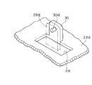
【図2】 本願発明の実施例を示す斜視図である。
【図3】 本願発明の実施例を示す一部拡大図である。
【図4】 従来例の側面図である。
【符号の説明】
14 処理トレイ
16 ストッパー
27 第1押圧板
28 第2押圧板
S シート[0001]
BACKGROUND OF THE INVENTION
The present invention relates to a sheet post-processing apparatus that binds sheets stacked on a processing tray by, for example, staples.
[0002]
[Prior art]
For example, a sheet post-processing apparatus that forms an image on a sheet by a copier, staples the sheet, and discharges the sheet is conventionally known.
FIG. 6 shows this conventional sheet post-processing apparatus. This processing apparatus discharges a sheet formed with an image by a copying machine without post-processing and a stapling process via a processing tray. The details of the route will be described below.
[0003]
The conventional post-processing apparatus main body M shown in FIG. 6 is attached to the copier main body C. In this attached state, the carry-in
In this way, the sheet S guided to the carry-in
[0004]
That is, when the flapper 5 is in the illustrated position, the sheet S guided to the passage 4 is guided from the passage 8 to the
That is, in this path, the sheets S are stacked one by one on a stacking tray (not shown) without being post-processed.
On the other hand, the sheet S conveyed to the passage 8 is discharged from the
[0005]
The sheet S guided to the path 8 in the staple processing path is transported to the
Therefore, when the
[0006]
As described above, the sheet S pushed out toward the
[0007]
Here, the
A
[0008]
Accordingly, the other end Sb of the sheet S that has left the
The
[0009]
Now, when a sensor (not shown) confirms that the sheet S passes through the
[0010]
The other end Sb of the sheet S pushed back to the processing apparatus main body M side by the
[0011]
As described above, the image-processed sheets S are successively conveyed, conveyed to the
When the determined number of sheets is stacked on the
[0012]
When the stapling process is completed as described above, the rotating
[0013]
When the rotating
The
[0014]
In such a sheet post-processing apparatus, since the bundle of sheets S stacked on the
Further, in the case of a copying machine that heat-fixes toner on the sheet S, the sheet S is distorted due to the heat. This distortion further increases the thickness of the bundle of stacked sheets S.
[0015]
As described above, the bundle of sheets S whose thickness is increased by the air layer is difficult to be stapled, and may not be satisfactorily bound. Further, not only the stapling process is difficult, but also the sheets S cannot be neatly arranged. In particular, the sheet S to which heat has been applied in order to heat-fix the toner is inevitably warped because the moisture content differs between the back side and the front side. When the warped sheets are stacked, the ends of the sheets are not evenly aligned.
In order to solve such a problem, the weight of the
[0016]
The pressing force of the
On the contrary, it is better to increase the pressing force as the thickness of the stack of stacked sheets increases. This is because if the thickness of the bundle of sheets S increases, the cushioning property of the bundle increases, so that even if it is pressed with a strong force, the sheet S is not damaged so much. On the other hand, if it is pressed with a strong force, the air between the sheets can be pushed out, which is advantageous for post-processing.
[0017]
[Problems to be solved by the invention]
However, in the conventional apparatus, the pressing force of the
As described above, since the weight of the
In addition to the stapling process, the sheet S cannot be neatly arranged.
[0018]
An object of the present invention is to provide a sheet post-processing apparatus capable of firmly pressing a sheet bundle when a large number of sheets formed with an image by a copying machine or the like are stacked and stapled.
[0019]
[Means for Solving the Problems]
1st invention has a processing tray and the conveyance mechanism which conveys the sheet | seat in which the image was formed one by one to a processing tray, and the said processing tray provided with the stopper which stops the movement with respect to the conveyance direction of the said sheet | seat , and said processing A sheet post-processing apparatus provided with a rotatable pressing means that presses the sheet in contact with the sheet placed on the tray is assumed. Based on the assumption that the sheet post-processing apparatus is used, the pressing means includes a first rotatable pressing member whose tip is in contact with the processing tray at an initial position and presses the sheet, and a tip at the initial position is the processing tray. When the stacking amount of the sheets in the processing tray is equal to or less than the distance formed between the second pressing member and the processing tray, only the first pressing member is included. The first pressing member and the second pressing member are in contact with the sheet in the processing tray when the sheet is in contact with the sheet in the processing tray and the stacking amount is equal to or greater than the distance formed between the second pressing member and the processing tray. The sheet is configured to press the sheet, and the tip of the second pressing member is located behind the tip of the first pressing member with the stopper of the processing tray as a base point .
[0020]
The second invention is characterized in that both the first pressing member and the second pressing member can be rotated to a position substantially parallel to the sheet placing portion of the processing tray .
[0021]
DETAILED DESCRIPTION OF THE INVENTION
1 to 3 show a first embodiment of the present invention, in which a first pressing
[0022]
The first pressing
Further, as shown in FIG. 3, a
[0023]
The first pressing
The first
[0024]
The second pressing
[0025]
In this way, the tip of the second pressing
Further, as shown in FIG. 2, the first pressing
[0026]
Further, the second pressing
[0027]
Next, the operation when the sheet is conveyed to the sheet post-processing apparatus of the first embodiment will be described.
In the sheet post-processing apparatus having the above-described configuration, when the sheet S is conveyed to the
[0028]
As described above, in the first embodiment, when the amount of stacked sheets S is small, only the pressing force of the first pressing
In addition, since the second pressing
[0029]
Further, when it is more the amount of lamination of the sheet S, the sheet S is to be subsequently conveyed, is conveyed to the
In the first embodiment, the first pressing
[0030]
[0031]
[0032]
[0033]
[0034]
[0035]
[0036]
[0037]
[0038]
In the above you施例, body M of the sheet post-processing apparatus, the copying machine main body C are provided separately, it may be incorporated together with the copier main body C.
Further, the staple processing has been described as an example of the post-processing method, but the present invention is not limited to the staple processing. For example, the post-processing method may be used when a hole is formed in several sheets S stacked. . In short, when the processing tray is used for the post-processing of the sheet S, it can be used for all.
[0039]
【The invention's effect】
According to the first aspect of the invention, as the number of sheets stacked on the processing tray increases, the sum of the pressing forces on the sheets is increased. Therefore, when the amount of stacked sheets is small, the sheets are damaged. It is possible to arrange the sheets neatly. Furthermore, when the amount of stacked sheets increases, the sheets can be firmly pressed, and post-processing with staples or the like can be easily performed.
[0040]
In addition, since the first pressing member whose tip is in contact with the processing tray in the initial position and the second pressing member that is held in the state where the tip is separated from the processing tray in the initial position, the stacking is performed on the processing tray. When the amount of the sheet to be applied is small, the sheet can be pressed by the pressing force of only the first pressing member, and after the amount of lamination increases and reaches the second pressing member, the first pressing member and the second pressing member are pressed. It can be pressed with both pressing forces with the member. Therefore, when the number of sheets is small, the sheets can be neatly aligned without damaging the sheets. In addition, since the pressing force can be increased with the amount of stacked sheets to firmly hold the sheets, the sheets can be neatly aligned at this time, and sheet post-processing can be facilitated.
[0041]
According to the second invention, both the first pressing member and the second pressing member can be rotated to a position substantially parallel to the sheet placing portion of the processing tray. The sheet can be pressed by the surfaces of the first and second pressing members.
[Brief description of the drawings]
FIG. 1 is a side view showing an embodiment of the present invention.
FIG. 2 is a perspective view showing an embodiment of the present invention.
FIG. 3 is a partially enlarged view showing an embodiment of the present invention.
FIG. 4 is a side view of a conventional example.
[Explanation of symbols]
14
Claims (2)
Priority Applications (2)
| Application Number | Priority Date | Filing Date | Title |
|---|---|---|---|
| JP2000120502A JP3673694B2 (en) | 2000-04-21 | 2000-04-21 | Sheet post-processing device |
| US09/590,270 US6412774B1 (en) | 1999-06-11 | 2000-06-09 | Sheet receiving apparatus |
Applications Claiming Priority (1)
| Application Number | Priority Date | Filing Date | Title |
|---|---|---|---|
| JP2000120502A JP3673694B2 (en) | 2000-04-21 | 2000-04-21 | Sheet post-processing device |
Publications (2)
| Publication Number | Publication Date |
|---|---|
| JP2001302068A JP2001302068A (en) | 2001-10-31 |
| JP3673694B2 true JP3673694B2 (en) | 2005-07-20 |
Family
ID=18631300
Family Applications (1)
| Application Number | Title | Priority Date | Filing Date |
|---|---|---|---|
| JP2000120502A Expired - Fee Related JP3673694B2 (en) | 1999-06-11 | 2000-04-21 | Sheet post-processing device |
Country Status (1)
| Country | Link |
|---|---|
| JP (1) | JP3673694B2 (en) |
Families Citing this family (11)
| Publication number | Priority date | Publication date | Assignee | Title |
|---|---|---|---|---|
| EP1348662A1 (en) * | 2002-03-29 | 2003-10-01 | Océ-Technologies B.V. | Sheet depositing device |
| JP4289915B2 (en) * | 2003-03-31 | 2009-07-01 | キヤノン株式会社 | Sheet discharging apparatus, sheet processing apparatus, and image forming apparatus |
| US7624975B2 (en) * | 2004-05-20 | 2009-12-01 | Xerox Corporation | Mechanism for retaining a stack of sheets in a compiler tray, such as for automatic stapling |
| US7980544B2 (en) | 2004-08-12 | 2011-07-19 | Max Co., Ltd. | Hold flap for sheet postprocessing apparatus |
| JP4920883B2 (en) * | 2004-11-05 | 2012-04-18 | キヤノン株式会社 | Sheet processing apparatus and image forming apparatus |
| JP4378264B2 (en) * | 2004-11-12 | 2009-12-02 | 株式会社リコー | Sheet stacking apparatus and image forming apparatus |
| JP4652089B2 (en) * | 2005-03-15 | 2011-03-16 | ニスカ株式会社 | Sheet processing device |
| JP4663571B2 (en) * | 2005-06-10 | 2011-04-06 | キヤノン株式会社 | Sheet stacking apparatus, sheet processing apparatus, and image forming apparatus |
| JP5174136B2 (en) * | 2010-11-29 | 2013-04-03 | キヤノン株式会社 | Sheet processing apparatus and image forming apparatus |
| US8958740B2 (en) | 2011-02-28 | 2015-02-17 | Brother Kogyo Kabushiki Kaisha | Configuration for a sheet discharging device |
| JP6582541B2 (en) | 2014-06-16 | 2019-10-02 | 株式会社リコー | Sheet processing apparatus and image forming system |
-
2000
- 2000-04-21 JP JP2000120502A patent/JP3673694B2/en not_active Expired - Fee Related
Also Published As
| Publication number | Publication date |
|---|---|
| JP2001302068A (en) | 2001-10-31 |
Similar Documents
| Publication | Publication Date | Title |
|---|---|---|
| JP4518173B2 (en) | Post-processing apparatus and paper processing system | |
| JP3732333B2 (en) | Finisher device | |
| JP3673694B2 (en) | Sheet post-processing device | |
| JP3937779B2 (en) | Post-processing apparatus and image forming system | |
| US20060244192A1 (en) | Processing device and image forming device | |
| JP3900964B2 (en) | Paper post-processing apparatus and image forming system | |
| JPH08137151A (en) | Sheet postprocessing device | |
| JP2001019268A (en) | Recording paper aftertreatment device of picture image formation device | |
| JP2002274734A (en) | Conveying device for releasing sheet stiffeness and sheet processing device and image forming device having the same | |
| JP2004099200A (en) | Paper sheet post-processing device and image forming system | |
| JP4056756B2 (en) | Paper post-processing device | |
| JP4089388B2 (en) | Post-processing equipment | |
| JP6037558B2 (en) | Sheet discharge device and image forming system using the same | |
| JP3902962B2 (en) | Sheet processing apparatus and image forming apparatus | |
| JP4006237B2 (en) | Sheet processing apparatus and image forming apparatus | |
| JP3931770B2 (en) | Paper post-processing method and paper post-processing apparatus | |
| JP3832322B2 (en) | Paper post-processing device | |
| JP3944636B2 (en) | Paper post-processing apparatus and image forming system | |
| JPH11130324A (en) | Paper post-processor | |
| JP2024074188A (en) | Sheet processing device and image forming system | |
| JP3663839B2 (en) | Sheet post-processing device | |
| JPH11130330A (en) | Sheet after-treatment device | |
| JP2001039618A (en) | Staple binding stacker | |
| JP5336316B2 (en) | Sheet stacking apparatus, post-processing apparatus including the same, and image forming system | |
| JP2009249049A (en) | Paper sheet post-processing device and image processing system |
Legal Events
| Date | Code | Title | Description |
|---|---|---|---|
| A977 | Report on retrieval |
Free format text: JAPANESE INTERMEDIATE CODE: A971007 Effective date: 20040507 |
|
| A131 | Notification of reasons for refusal |
Free format text: JAPANESE INTERMEDIATE CODE: A131 Effective date: 20041019 |
|
| A521 | Written amendment |
Free format text: JAPANESE INTERMEDIATE CODE: A523 Effective date: 20041220 |
|
| TRDD | Decision of grant or rejection written | ||
| A01 | Written decision to grant a patent or to grant a registration (utility model) |
Free format text: JAPANESE INTERMEDIATE CODE: A01 Effective date: 20050329 |
|
| A61 | First payment of annual fees (during grant procedure) |
Free format text: JAPANESE INTERMEDIATE CODE: A61 Effective date: 20050425 |
|
| R150 | Certificate of patent or registration of utility model |
Ref document number: 3673694 Country of ref document: JP Free format text: JAPANESE INTERMEDIATE CODE: R150 Free format text: JAPANESE INTERMEDIATE CODE: R150 |
|
| FPAY | Renewal fee payment (event date is renewal date of database) |
Free format text: PAYMENT UNTIL: 20080428 Year of fee payment: 3 |
|
| FPAY | Renewal fee payment (event date is renewal date of database) |
Free format text: PAYMENT UNTIL: 20090428 Year of fee payment: 4 |
|
| R250 | Receipt of annual fees |
Free format text: JAPANESE INTERMEDIATE CODE: R250 |
|
| FPAY | Renewal fee payment (event date is renewal date of database) |
Free format text: PAYMENT UNTIL: 20090428 Year of fee payment: 4 |
|
| FPAY | Renewal fee payment (event date is renewal date of database) |
Free format text: PAYMENT UNTIL: 20100428 Year of fee payment: 5 |
|
| R250 | Receipt of annual fees |
Free format text: JAPANESE INTERMEDIATE CODE: R250 |
|
| FPAY | Renewal fee payment (event date is renewal date of database) |
Free format text: PAYMENT UNTIL: 20100428 Year of fee payment: 5 |
|
| FPAY | Renewal fee payment (event date is renewal date of database) |
Free format text: PAYMENT UNTIL: 20110428 Year of fee payment: 6 |
|
| R250 | Receipt of annual fees |
Free format text: JAPANESE INTERMEDIATE CODE: R250 |
|
| FPAY | Renewal fee payment (event date is renewal date of database) |
Free format text: PAYMENT UNTIL: 20110428 Year of fee payment: 6 |
|
| FPAY | Renewal fee payment (event date is renewal date of database) |
Free format text: PAYMENT UNTIL: 20120428 Year of fee payment: 7 |
|
| R250 | Receipt of annual fees |
Free format text: JAPANESE INTERMEDIATE CODE: R250 |
|
| FPAY | Renewal fee payment (event date is renewal date of database) |
Free format text: PAYMENT UNTIL: 20130428 Year of fee payment: 8 |
|
| R250 | Receipt of annual fees |
Free format text: JAPANESE INTERMEDIATE CODE: R250 |
|
| FPAY | Renewal fee payment (event date is renewal date of database) |
Free format text: PAYMENT UNTIL: 20140428 Year of fee payment: 9 |
|
| R250 | Receipt of annual fees |
Free format text: JAPANESE INTERMEDIATE CODE: R250 |
|
| R250 | Receipt of annual fees |
Free format text: JAPANESE INTERMEDIATE CODE: R250 |
|
| R250 | Receipt of annual fees |
Free format text: JAPANESE INTERMEDIATE CODE: R250 |
|
| R250 | Receipt of annual fees |
Free format text: JAPANESE INTERMEDIATE CODE: R250 |
|
| R250 | Receipt of annual fees |
Free format text: JAPANESE INTERMEDIATE CODE: R250 |
|
| S111 | Request for change of ownership or part of ownership |
Free format text: JAPANESE INTERMEDIATE CODE: R313111 |
|
| R350 | Written notification of registration of transfer |
Free format text: JAPANESE INTERMEDIATE CODE: R350 |
|
| R250 | Receipt of annual fees |
Free format text: JAPANESE INTERMEDIATE CODE: R250 |
|
| LAPS | Cancellation because of no payment of annual fees |