JP3672943B2 - Hydraulic clamping element - Google Patents
Hydraulic clamping element Download PDFInfo
- Publication number
- JP3672943B2 JP3672943B2 JP11119694A JP11119694A JP3672943B2 JP 3672943 B2 JP3672943 B2 JP 3672943B2 JP 11119694 A JP11119694 A JP 11119694A JP 11119694 A JP11119694 A JP 11119694A JP 3672943 B2 JP3672943 B2 JP 3672943B2
- Authority
- JP
- Japan
- Prior art keywords
- wedge
- compensating
- annular piston
- clamping
- element according
- Prior art date
- Legal status (The legal status is an assumption and is not a legal conclusion. Google has not performed a legal analysis and makes no representation as to the accuracy of the status listed.)
- Expired - Fee Related
Links
Images


Classifications
-
- B—PERFORMING OPERATIONS; TRANSPORTING
- B23—MACHINE TOOLS; METAL-WORKING NOT OTHERWISE PROVIDED FOR
- B23B—TURNING; BORING
- B23B31/00—Chucks; Expansion mandrels; Adaptations thereof for remote control
- B23B31/02—Chucks
- B23B31/24—Chucks characterised by features relating primarily to remote control of the gripping means
- B23B31/30—Chucks characterised by features relating primarily to remote control of the gripping means using fluid-pressure means in the chuck
- B23B31/302—Hydraulic equipment, e.g. pistons, valves, rotary joints
-
- B—PERFORMING OPERATIONS; TRANSPORTING
- B23—MACHINE TOOLS; METAL-WORKING NOT OTHERWISE PROVIDED FOR
- B23B—TURNING; BORING
- B23B31/00—Chucks; Expansion mandrels; Adaptations thereof for remote control
- B23B31/40—Expansion mandrels
- B23B31/4073—Gripping the work or tool between planes almost perpendicular to the axis
-
- Y—GENERAL TAGGING OF NEW TECHNOLOGICAL DEVELOPMENTS; GENERAL TAGGING OF CROSS-SECTIONAL TECHNOLOGIES SPANNING OVER SEVERAL SECTIONS OF THE IPC; TECHNICAL SUBJECTS COVERED BY FORMER USPC CROSS-REFERENCE ART COLLECTIONS [XRACs] AND DIGESTS
- Y10—TECHNICAL SUBJECTS COVERED BY FORMER USPC
- Y10T—TECHNICAL SUBJECTS COVERED BY FORMER US CLASSIFICATION
- Y10T279/00—Chucks or sockets
- Y10T279/12—Chucks or sockets with fluid-pressure actuator
-
- Y—GENERAL TAGGING OF NEW TECHNOLOGICAL DEVELOPMENTS; GENERAL TAGGING OF CROSS-SECTIONAL TECHNOLOGIES SPANNING OVER SEVERAL SECTIONS OF THE IPC; TECHNICAL SUBJECTS COVERED BY FORMER USPC CROSS-REFERENCE ART COLLECTIONS [XRACs] AND DIGESTS
- Y10—TECHNICAL SUBJECTS COVERED BY FORMER USPC
- Y10T—TECHNICAL SUBJECTS COVERED BY FORMER US CLASSIFICATION
- Y10T403/00—Joints and connections
- Y10T403/16—Joints and connections with adjunctive protector, broken parts retainer, repair, assembly or disassembly feature
- Y10T403/1633—Utilizing fluid pressure
-
- Y—GENERAL TAGGING OF NEW TECHNOLOGICAL DEVELOPMENTS; GENERAL TAGGING OF CROSS-SECTIONAL TECHNOLOGIES SPANNING OVER SEVERAL SECTIONS OF THE IPC; TECHNICAL SUBJECTS COVERED BY FORMER USPC CROSS-REFERENCE ART COLLECTIONS [XRACs] AND DIGESTS
- Y10—TECHNICAL SUBJECTS COVERED BY FORMER USPC
- Y10T—TECHNICAL SUBJECTS COVERED BY FORMER US CLASSIFICATION
- Y10T403/00—Joints and connections
- Y10T403/22—Joints and connections with fluid pressure responsive component
-
- Y—GENERAL TAGGING OF NEW TECHNOLOGICAL DEVELOPMENTS; GENERAL TAGGING OF CROSS-SECTIONAL TECHNOLOGIES SPANNING OVER SEVERAL SECTIONS OF THE IPC; TECHNICAL SUBJECTS COVERED BY FORMER USPC CROSS-REFERENCE ART COLLECTIONS [XRACs] AND DIGESTS
- Y10—TECHNICAL SUBJECTS COVERED BY FORMER USPC
- Y10T—TECHNICAL SUBJECTS COVERED BY FORMER US CLASSIFICATION
- Y10T409/00—Gear cutting, milling, or planing
- Y10T409/30—Milling
- Y10T409/30952—Milling with cutter holder
Description
【0001】
【産業上の利用分野】
本発明は、円板状または軸状の回転締付け片、例えば工作物、工具、特にホブ等を、心棒上で軸方向に締付けるための液圧式締付け要素であって、心棒に取付け可能な本体を備え、この本体に環状ピストンが浮動支承され、この環状ピストンが閉鎖液圧系を介して、本体と相対的に締付け片の方へ移動可能であり、その際、締付け片が軸方向にしっかりと締付けられ、締付け要素の長手軸線に対して対称なくさび面を有する押圧要素が設けられ、この押圧要素が半径方向に移動可能な補整ボルトによって軸方向に摺動可能であり、かつ所望の締付け位置に固定可能であるような液圧式締付け要素に関する。
【0002】
【従来の技術】
この種の公知の締付け要素(ドイツ連邦共和国特許出願公開第3941765号明細書)は、締付け片、例えばホブまたは他の回転工具あるいは回転する工作物を調整するために、押圧要素として、くさび状の半径方向横断面を有する円錐押圧リングを備えている。この円錐押圧リングは、ゴムリングによって位置決めされて、環状ピストンの軸方向延長部を比較的に大きな半径方向遊びによって取り囲んでいる。軸方向に見て、この円錐押圧リングは液圧式締付け要素の本体に装着された調節可能なねじ付きリングと、スリーブによって心棒にねじ込まれた弾性的な半径方向フランジとの間に設けられ、押圧リングの円錐面が弾性的なフランジの対応する斜面に接触している。円錐押圧リングの半径方向の押圧ボルトはその適切な半径方向調節、ひいては軸方向締付け力の所望な加減を可能にし、それによって心棒、液圧締付け要素、この心棒に締付けられる締付け片、すなわち回転工具、例えばホブ、工作物等からなる系が適切な位置に調節される、すなわち偏心が避けられるように調整される。
【0003】
その際、公知の液圧式締付け要素は調整後、液圧付勢される環状ピストンの負荷解除を可能にする。なぜなら、皿形のフランジが円錐押圧リングとねじ付きリングによってその調整位置に固定されるからである。
【0004】
この公知締付け要素の場合には、技術的コストがかかり、特にねじ付きリングと円錐押圧リングによってこれらと一緒にセンタリングを行うゴムリングが比較的に長い構造長さを有するという欠点がある。
【0005】
【発明が解決しようとする課題】
本発明の課題は、構造が簡単であると共に、軸方向の構造長さが短く、容易に操作することができ、特にセット時の偏心の正確な調整を可能にする、冒頭に述べた種類の液圧式締付け要素を提供することである。
【0006】
【課題を解決するための手段】
この課題は本発明に従い、押圧要素が環状ピストンに保持された複数の補整くさびによって形成され、この補整くさびが液圧式締付け要素の長手軸線の方へ調節可能であることによって解決される。押圧要素が公知の場合のように閉じた補整リング、すなわち円錐押圧リングではなく、締付け要素の長手軸線に対して対称に設けられた環状ピストンに保持された調節可能な複数の補整くさびによって形成されることにより、付加的な支持リングが不要である。本発明に従って設けられた個々の補整くさびは、複数のサイズの締付け要素のために使用可能であり、かつ簡単に製作可能である。従って、本発明による締付け要素は製作上の利点を有する。補整くさびのすべての補整ボルトを均一に締めることによって、弾性的な半径方向フランジが設けられている場合にも、回転体に対する均一な軸方向支持が達成される。必要な場合には個々の補整ボルト、ひいては補整くさびを適切に操作することにより、工具または工作物の回転が非常に正確であり、かつ容易に調節可能である。補整ボルトを備えた、4〜10個、特に8個の補整くさびが締付け要素の周囲に均一に分配配置されると有利である。本発明による解決策の他の利点は、締付け要素の簡単な構造が操作ミスをほとんど無くすことにある。本発明は更に、環状ピストンの負荷解除時、すなわち液圧装置の戻し時に、調整された回転つりあいを維持したままにすることを保証する。これは、スリーブ状の補整くさびが特にその頭部に設けられたくさびとしての斜面を有し、この斜面に、締付け要素の本体の対応する斜面が付設され、補整ボルトの半径方向調節時に、すなわち調整開始時に、補整くさびが調節されたセット位置で本体に支持されていることによって達成される。これにより、回転締付け片、すなわち工具または工作物と、補整くさびと、心棒にねじ込まれた締付け要素の本体との間でのしっかりした機械的支持が達成され、しかも次に説明する特別な実施例において半径方向の弾性フランジを備えたスリーブが設けられているときにも達成される。このスリーブ自体はおねじ部によって本体を収容している。
【0007】
【実施例】
次に、図を参照して、本発明の対象物の他の有利な構成を、若干の実施例に基づいて詳しく説明する。
【0008】
本発明のすべての実施例において、円板状または軸状の締付け片1の形をした回転体、例えば工作物、工具、特にホブ等が、心棒2に嵌め込まれている。この回転締付け片は、心棒の図示していない他端で、つばまたは類似のストッパーに接触している。
【0009】
心棒2の図示した自由端部には、本体3とその中に浮動支承された環状ピストン7を備えた締付け要素がねじ込まれている。実施例A(図1〜8)、実施例B(図9,10)および実施例D(図15〜18)の場合、締付け要素の本体3はスリーブ8のおねじ部17にねじ込まれている。このスリーブ自体はめねじ部16によってフライス心棒2に装着されている。スリーブ8は皿ばねのように弾性的に設けられた半径方向のフランジ13を備えている。このフランジは締付け片1(工具または工作物)に接触する接触面14(図8参照)と、この接触面と反対側の、環状ピストン7寄りの接触面15を備えている。
【0010】
従って、実施例A,B,Dの場合、本体3はスリーブ8に動かぬようねじ込まれている。
【0011】
図13,14は実施例Cを示している。この実施例の場合には、弾性的なフランジ13が省略され、環状ピストン7は回転締付け片1の環状ピストン寄りの平らな面に直接接触している。
【0012】
すべての実施例において、本体3はボルト9によってスリーブ8または心棒2と相対的なその位置に保持することが可能である。
【0013】
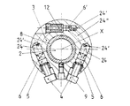
本体3内には、シール6,6と押圧ボルト4,4を備えた円筒状の二つの液圧通路24,24が設けられている(図2参照)。この液圧通路24は穴を介して軸方向に移動可能な環状ピストン7に接続されている(特に図1参照)。この環状ピストンの前にはシール要素6が配置されている。本体3内には更に、シール6’を備えた締付け力表示部12が設けられている。この締付け力表示部は、環状ピストン7の前にある環状通路24”(図2参照)に液圧的に接続されている。環状ピストン7は浮動支承され、閉鎖液圧系を介して本体3と相対的に軸方向に摺動可能である。ボルト4によって適当な締付け力が加えられると、環状ピストンは回転締付け片1の方へ移動し、回転締付け片を締め付けることになる。
【0014】
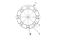
環状ピストン7と、工具または工作物のこの環状ピストン寄りの接触面との間には、押圧要素が設けられている。この押圧要素は本発明に従って、液体締付け要素の長手軸線に対して対称に設けられかつ環状ピストン7に装着された調節可能な複数の補整くさび11によって形成されている。図3から判るように、支持くさびと呼ぶこともできるこの補整くさびは、環状ピストン7の周囲に均一に分配配置されている。この場合、締付け要素の大きさに応じて、4個以上、特に8個の補整くさびを設けると有利である。この補整くさびは、個々の補整くさび11が回転締付け片1寄りの環状ピストン7の締付け面7’上に半径方向に設けられ、半径方向に調節可能な補整ボルト10を1個ずつ備えるように配置されている。この補整ボルトはねじ付きピンのように簡単に形成されている。
【0015】
図1〜8の実施例Aの場合の補整くさび11、すなわち支持くさびは、図4,5に拡大して詳細に示してある。図6,7はこの補整くさび11を収容するための本発明に従って形成された環状ピストン7を示している。
【0016】
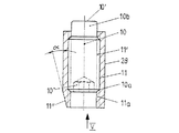
実施例Aでは、ほぼスリーブ状に形成された補整くさび11の横断面は四角形、特に正方形に形成されている。この補整くさびの内部には、めねじ部11’によってねじ付きピンのような補整ボルト10が半径方向に調節可能に設けられている。めねじ部11’のコア直径は10aで示してある。補整ボルト10はその脚部の範囲に、ピン状の突起10bを備えている。この突起の底10’は、実施例A,B,Dでは、ねじ込み状態でスリーブ8の接続部8’の外周面に接触している。反対側の頭部範囲は穴付きボルトのように形成されている。
【0017】
実施例A〜Dのすべての補整くさび11はスリーブ状に形成され、くさびとして、その頭側の自由端部の範囲にある斜面11”を備えている。この斜面は本体の斜面11'''に対応して配置され、図8に記入した環状矢印の方向に補整ボルト10を半径方向に調節すると、この補整くさび11はその底10’が接続部8’に接触しているので、矢印H方向に(図8,9,13参照)、すなわち半径方向外方へ移動する。この場合、補整くさび11の傾斜した面11”は、動かない本体3の対応する斜面11'''に乗り上げ、それによって矢印S方向に作用する締付け力をフランジ13に加える。なぜなら、補整くさび11の外面11bがフランジ13の接触面15を押し、それによってフランジの反対側の接触面14が締付け片(回転工具)1の対応する接触面に押し付けられるからである。
【0018】
これを行うために、各補整くさび11は環状ピストン7の収容部18内で保持されている(図6,7参照)。実施例Aの場合には、収容部18は補整くさび11(図4,5参照)の長方形または正方形の横断面に相応して溝状に形成され、しかも補整くさび11は補整ボルト10の回転に相応して収容部18内で半径方向に摺動可能である。
【0019】
補整くさび11の斜面11”と本体3の斜面11'''はそれぞれ半径方向に対して角度αをなしている。この角度は10〜30度とすることができる。角度αは好ましくは、分解の際誤って先ず最初に液圧を低下させ、そして初めて補整ボルト10を弛めるときに、自己ロックが生じないように選定される。これは重要な利点である。なぜなら、この種の技術水準では常に、液圧が低下する前に、先ず最初に支持リングを弛めなければならず、もしそうしないと支持リングが締付けられて動かなくなるからである。図示実施例の場合、補整くさび11の斜面11”が本体3寄りのくさび11の面に設けられているので、本体の相手方斜面11'''との直接的な協働が可能である。
【0020】
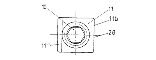
補整くさび11は前述のように、環状ピストン7の収容部18内に設けられている。そのために、環状ピストン7は軸方向に突出する突出部19(図7,18参照)を備えている。この突出部19内に収容部18が設けられている。図1〜8の実施例Aの場合、すなわち補整くさびが正方形に形成されている場合には、補整くさび11の平らな表面11bは、締付け片(回転工具)1の方へ加えられる締付け力の押圧面を形成している。収容部18の間にある、環状ピストン7のセグメント状の面区間(締付け面7’)は同様に、フランジ13のための接触面を形成している。
【0021】
実施例A,B,Dの場合には、本体3はスリーブ8にねじ込まれている。このスリーブは弾性的な半径方向フランジ13を備え、この半径方向フランジ自体は、環状ピストン7用の接触面15または環状ピストン7内で案内されている補整くさび11の押圧面11bを形成している(図5の押圧面11b参照)。半径方向フランジ13の他方の平行な面は回転締付け片1の接触面14を形成している。皿形のフランジ13を設けたことにより、特に運転中の切断力によって生じるような半径方向の移動力はもはや環状ピストン7に作用せず、弾性的な皿形のフランジ13によって受け止められる。特に環状ピストン7の繰り出し時に幾らか発生する不均一な運動は皿形のフランジ13によって補整される。
【0022】
図9〜12に示す実施例Bは、補整くさび11の横断面が円形である点だけが、実施例Aと異なっている。機能は実施例Aの機能と同じである。図9〜12と他の図において、同じ部品には同じ参照符号が付けてある。実施例Bの場合には、円形の補整くさび11は環状ピストン7の円筒状収容部18内に装着されている。この収容部は軸方向に突出する環状の突出部19に設けられている。この場合、環状面7cは図9,10から判るように、フランジ13の接触面15に直接接触している。補整くさび11にねじ込まれた、おねじ部を備えた補整ボルト10が、記入したリング状矢印(図9参照)の方向にねじ込まれると、補整くさびが底10’でスリーブ8の対向面8’に接触しているときには、補整くさび11は半径方向外方へ向かって矢印Hの方向へ移動し、矢印Sの方向に作用する締付け力をフランジ13に発生する。このフランジの接触面14は締付け片(回転工具)1の対応する端面に押し付けられる。補整くさび11の斜面11”が外方へ押されるので、締付け力が発生する。それによって、本体の斜面11'''に接触し、締付け片(回転工具)1に作用する締付け力が支持される。
【0023】
図13,14の実施例Cの場合には、実施例Bの場合と同様に、補整ボルト10は横断面が円形の補整くさび11内にある。この補整くさびは実施例Bの場合と同様に、円形横断面の収容部18内で半径方向に摺動可能である。実施例A,B,Dとの違いは、そこに設けられ圧液を戻す、中間配置された要素としての皿状のフランジ13が省略され、それによって環状ピストン7の半径方向締付け面7’(図13参照)が締付け片(回転工具)1の半径方向の平らな面に直接押し付けられることにある。すなわち、この実施例の場合には、補整くさび11の斜面11”が、浮動環状ピストン7内で支承されて、本体3と回転締付け片1の対向締付け面との間で直接締付けられる。締付け作用は他の実施例の場合と同様に、図13に記入した環状矢印の方向に補整ボルト10を回転させることによって生じる。それによって、補整くさび11が半径方向(矢印H)に移動してその斜面11”が本体の対応する斜面11'''に乗り上げ、方向Sに作用する締付け力が発生する。
【0024】
図15〜18の実施例Dは基本的には実施例A,Bの構造と一致している。しかし、本実施例では弾性要素として弾性リング25が設けられている。この弾性リングは、補整ボルト10が弛められるや否や、補整くさび11を自動的に戻す。本実施例では、弾性リング25は拡開可能な開放したリングである。このリングは補整ボルト10を戻す際(矢印S’参照)収縮し、矢印N方向に作用する戻し力を環状ピストン7に、ひいては補整くさび11に加える。この弾性リングは図16,17に本実施例として詳細に示してある。図18は本実施例Dの環状ピストンDを半径方向から見た部分断面図である。この図から判るように、補整くさび11用の収容部18は円形ではなく、補整くさびの形状に相応して横断面が四角形、特に正方形に形成されている。図15は環状ピストン7、補整くさび11および補整ボルト10を示している。図示状態では、補整ボルトが弛められ、すなわち液圧が低下し、弾性リング20の作用によって補整くさび11が元の位置へ自動的に戻っている。
【0025】
図示実施例の操作は次のように行われる。すなわち、先ず最初に、実施例A,B,Dの場合に、弾性フランジ13の接触面14が締付け片(回転工具)1の対向締付け面に充分に接触するまで、締付け要素全体が心棒2にねじ込まれる。そして、押圧ボルト4が締められ、それによって所望の締付け力が得られるまで液圧系内の圧力が上昇する。この締付け力は締付け力表示部12に表示される。その後、すべての補整ボルト10が均一に締められ、それによって実施例A,B,Dの場合には弾性フランジ13が補整くさび11によって本体3に軸方向に支持される。従って、締付け片(回転工具)1と締付け要素の締付け本体3との間に、機械的に作用する固定支持部が形成される。個々の補整ボルト10を適切に後調節することによって、回転締付け片1の回転が最適に調節可能である。その後、調節された固定支持部を解除しないで、液圧系の圧力を抜くことができる。更に、前述のように、補整くさび11または本体3のくさび斜面の角度αは、自己ロックしないように選定されている。従って、分解時に誤って先ず最初に液圧を抜いて、そして初めて補整ボルトを弛めるときには、前述のように、公知の解決策に比べて、液圧を抜く前に常に最初に支持リングを弛めるよう注意する必要がない。それによって、支持リングが締付けられて動かなくなることや支持リングの負荷を解除するために液圧装置を再操作することが回避される。
【0026】
【発明の効果】
以上説明したように、本発明の液圧式締付け要素は、構造が簡単であると共に、軸方向の構造長さが短く、容易に操作することができ、特にセット時の偏心の正確な調整が可能であるという利点を有する。更に、付加的な支持リングが不要であり、個々の補整くさびが複数のサイズの締付け要素のために使用可能であり、かつ簡単に製作可能であり、そして弾性的な半径方向フランジが設けられている場合にも、回転体に対する均一な軸方向支持が達成されるという利点がある。
【図面の簡単な説明】
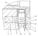
【図1】 心棒とこの心棒に装着された工具と共に、本発明による締付け要素の実施例「A」を示す部分断面図である。
【図2】 図1のII−II線に沿った断面図である。
【図3】 図1のIII−III線に沿った断面図である。
【図4】 図1の補整くさびの断面図である。
【図5】 図4の矢印V方向の矢視図である。
【図6】 図1〜5の実施例における環状ピストンの平面図である。
【図7】 環状ピストンを半径方向から見た部分断面図である。
【図8】 図1の部分断面図の拡大図である。
【図9】 円筒状補整くさびを備えた変形例「B」の部分断面図である。
【図10】 図9の変形例を半径方向から見た部分図である。
【図11】 変形例「B」の環状ピストンの部分断面平面図である。
【図12】 変形例「B」の環状ピストンの部分断面側面図である。
【図13】 変形例「C」の環状ピストンの部分断面平面図である。
【図14】 変形例「C」の環状ピストンの部分断面側面図である。
【図15】 第3の変形例「D」における環状ピストンの部分断面平面図である。
【図16】 図15の実施例の開放した弾性止め輪の正面図である。
【図17】 図15の実施例の開放した弾性止め輪の側面図である。
【図18】 弾性止め輪を備えた図15の実施例の環状ピストンの部分断面図である。
【符号の説明】
1 締付け片(工具または工作物)
2 心棒
3 本体
7 環状ピストン
7’ 環状ピストンの締付け面
8 スリーブ
8’ スリーブの部分
10 補整ボルト
11 補整くさび
11b 外側の面
11” 補整くさびの斜面
11''' 本体の斜面
13 半径方向フランジ
14 接触面
15 接触面
16 めねじ部
17 おねじ部
18 収容部
19 突出部
25 リング
S 締付け力の方向
X 液圧式締付け要素の長手軸線[0001]
[Industrial application fields]
The present invention relates to a hydraulic clamping element for axially clamping a disk-like or shaft-like rotary fastening piece, such as a workpiece, a tool, in particular a hob, etc. An annular piston is floated on the main body, and the annular piston can be moved toward the clamping piece relative to the main body via the closed hydraulic system, with the clamping piece being firmly fixed in the axial direction. A clamping element is provided which is clamped and has a wedge surface symmetrical to the longitudinal axis of the clamping element, the pressing element being slidable in the axial direction by means of a compensation bolt which is movable in the radial direction, and the desired clamping position To a hydraulic clamping element which can be fixed to
[0002]
[Prior art]
A known clamping element of this kind (German
[0003]
In so doing, the known hydraulic clamping elements enable the release of the hydraulically biased annular piston after adjustment. This is because the dish-shaped flange is fixed in its adjusted position by the conical pressing ring and the threaded ring.
[0004]
This known clamping element is technically costly and has the disadvantage that the rubber ring, which is centered therewith by means of a threaded ring and a conical pressing ring, has a relatively long structural length.
[0005]
[Problems to be solved by the invention]
The object of the present invention is that the structure of the kind mentioned at the beginning is simple, the structure length in the axial direction is short, it can be operated easily and, in particular, it enables the precise adjustment of the eccentricity during setting. It is to provide a hydraulic clamping element.
[0006]
[Means for Solving the Problems]
This object is solved according to the invention by the fact that the pressing element is formed by a plurality of compensating wedges held by an annular piston, the compensating wedge being adjustable towards the longitudinal axis of the hydraulic clamping element. The pressing element is not formed by a closed compensating ring as in the known case, i.e. a conical pressing ring, but by a plurality of adjustable compensating wedges held on an annular piston provided symmetrically with respect to the longitudinal axis of the clamping element. This eliminates the need for an additional support ring. The individual compensating wedges provided according to the invention can be used for multiple sizes of clamping elements and can be easily manufactured. Accordingly, the clamping element according to the invention has manufacturing advantages. Uniform axial support for the rotating body is achieved, even when elastic radial flanges are provided, by evenly tightening all the compensating bolts of the compensating wedge. By appropriately operating the individual adjusting bolts, and thus the adjusting wedges, if necessary, the rotation of the tool or workpiece is very accurate and easily adjustable. It is advantageous if 4-10, in particular 8 compensating wedges with compensating bolts are distributed evenly around the clamping element. Another advantage of the solution according to the invention is that the simple structure of the clamping element eliminates almost no operating errors. The present invention further ensures that the adjusted rotational balance remains maintained when the annular piston is unloaded, i.e. when the hydraulic device is returned. This is because the sleeve-like compensating wedge has a bevel, in particular a wedge provided at its head, to which the corresponding bevel of the body of the clamping element is attached, during the radial adjustment of the compensating bolt, i.e. This is accomplished by having the compensating wedge supported on the body at the adjusted set position at the start of adjustment. This achieves a firm mechanical support between the rotary clamping piece, i.e. the tool or workpiece, the compensating wedge and the body of the clamping element screwed into the mandrel, and a special embodiment which will be described next. This is also achieved when a sleeve with a radial elastic flange is provided. The sleeve itself accommodates the main body by a male screw portion.
[0007]
【Example】
Next, with reference to the figures, other advantageous configurations of the object of the invention will be described in detail on the basis of some embodiments.
[0008]
In all embodiments of the invention, a rotating body in the form of a disc-like or shaft-
[0009]
At the illustrated free end of the
[0010]
Therefore, in the case of Examples A, B, and D, the
[0011]
13 and 14 show Example C. In this embodiment, the
[0012]
In all embodiments, the
[0013]
In the
[0014]
A pressing element is provided between the
[0015]
The compensating
[0016]
In Example A, the cross-sectional shape of the compensating
[0017]
All the compensating
[0018]
In order to do this, each compensating
[0019]
The
[0020]
The correcting
[0021]
In the case of Examples A, B and D, the
[0022]
The embodiment B shown in FIGS. 9 to 12 differs from the embodiment A only in that the cross section of the compensating
[0023]
In the case of Example C in FIGS. 13 and 14, as in the case of Example B, the compensating
[0024]
The embodiment D in FIGS. 15 to 18 basically matches the structure of the embodiments A and B. However, in this embodiment, an
[0025]
The operation of the illustrated embodiment is performed as follows. That is, first, in the case of Examples A, B, and D, the entire tightening element is attached to the
[0026]
【The invention's effect】
As described above, the hydraulic clamping element of the present invention has a simple structure and a short axial structure length, which can be easily operated, and in particular, the eccentricity during setting can be accurately adjusted. It has the advantage of being. Furthermore, no additional support ring is required, individual compensating wedges can be used for multiple sizes of clamping elements and can be easily manufactured and provided with elastic radial flanges Even in this case, there is an advantage that uniform axial support for the rotating body is achieved.
[Brief description of the drawings]
FIG. 1 is a partial sectional view showing an embodiment “A” of a clamping element according to the invention, together with a mandrel and a tool mounted on the mandrel.
FIG. 2 is a cross-sectional view taken along the line II-II in FIG.
FIG. 3 is a cross-sectional view taken along line III-III in FIG.
FIG. 4 is a cross-sectional view of the compensating wedge of FIG.
FIG. 5 is a view taken in the direction of arrow V in FIG.
FIG. 6 is a plan view of an annular piston in the embodiment of FIGS.
FIG. 7 is a partial cross-sectional view of the annular piston as seen from the radial direction.
8 is an enlarged view of a partial cross-sectional view of FIG.
FIG. 9 is a partial cross-sectional view of a modification “B” including a cylindrical compensating wedge.
FIG. 10 is a partial view of the modification of FIG. 9 viewed from the radial direction.
FIG. 11 is a partial cross-sectional plan view of an annular piston of a modification “B”.
FIG. 12 is a partial cross-sectional side view of an annular piston of a modification “B”.
FIG. 13 is a partial cross-sectional plan view of an annular piston of a modification “C”.
FIG. 14 is a partial cross-sectional side view of an annular piston of a modification “C”.
FIG. 15 is a partial cross-sectional plan view of an annular piston in a third modification “D”.
16 is a front view of the opened elastic retaining ring of the embodiment of FIG.
FIG. 17 is a side view of the opened elastic retaining ring of the embodiment of FIG.
18 is a partial cross-sectional view of the annular piston of the embodiment of FIG. 15 with an elastic retaining ring.
[Explanation of symbols]
1 Tightening piece (tool or workpiece)
2
Claims (13)
上記押圧要素が、上記環状ピストン(7)に保持された複数の補整くさび(11)によって形成されており、その際、当該補整くさび(11)が斜面(11”)を有し、この斜面に対応する斜面(11''')を、本体(3)が有し、それら斜面(11”、11''')によって、上記補整くさび(11)が液圧式締付け要素の長手軸線(X)の方に調節可能であることを特徴とする液圧式締付け要素。A hydraulic clamping element for axially clamping a disc-like or shaft-like rotary clamping piece (1), for example, a workpiece, a tool, in particular a hob, etc. on the mandrel (2), the mandrel (2) A body (3) attachable to the body, and an annular piston (7) is floated on the body, and the annular piston is positioned relative to the body (3) via a closed hydraulic system. ), The clamping piece (1) being firmly clamped in the axial direction, and a pressing element having a wedge surface symmetrical to the longitudinal axis of the clamping element is provided. In a hydraulic clamping element that is slidable in the axial direction by means of a radially movable adjusting bolt and that can be fixed in a desired clamping position,
The pressing element is formed by a plurality of compensating wedges (11) held by the annular piston (7). At this time, the compensating wedge (11) has a slope (11 ″), The body (3) has a corresponding bevel (11 ′ ″), by means of which the bevels (11 ″, 11 ′ ″) cause the compensating wedge (11) to move along the longitudinal axis (X) of the hydraulic clamping element. Hydraulic clamping element characterized in that it can be adjusted in a direction.
Applications Claiming Priority (2)
| Application Number | Priority Date | Filing Date | Title |
|---|---|---|---|
| DE4317502A DE4317502A1 (en) | 1993-05-26 | 1993-05-26 | Hydraulic tensioning element |
| DE4317502.3 | 1993-05-26 |
Publications (2)
| Publication Number | Publication Date |
|---|---|
| JPH071210A JPH071210A (en) | 1995-01-06 |
| JP3672943B2 true JP3672943B2 (en) | 2005-07-20 |
Family
ID=6488950
Family Applications (1)
| Application Number | Title | Priority Date | Filing Date |
|---|---|---|---|
| JP11119694A Expired - Fee Related JP3672943B2 (en) | 1993-05-26 | 1994-05-25 | Hydraulic clamping element |
Country Status (4)
| Country | Link |
|---|---|
| US (1) | US5435577A (en) |
| EP (1) | EP0630721B1 (en) |
| JP (1) | JP3672943B2 (en) |
| DE (2) | DE4317502A1 (en) |
Families Citing this family (11)
| Publication number | Priority date | Publication date | Assignee | Title |
|---|---|---|---|---|
| FI932943A (en) * | 1993-06-24 | 1994-12-25 | Irri Oy | Automatic tool change |
| DE19641133C2 (en) * | 1996-10-05 | 1999-03-04 | Erhard Schaefer | Exchange device for shaft-hub connections |
| US6390723B1 (en) | 1996-10-05 | 2002-05-21 | Schaefer Erhard | Changing device for shaft/hub connections |
| DE29704245U1 (en) | 1997-03-06 | 1997-06-26 | Rinne Erkki | Hydraulic press assemblies |
| DE19710552A1 (en) * | 1997-03-14 | 1998-09-17 | Schloemann Siemag Ag | Connection between the spindle head of a tooth or universal joint spindle and a roll neck |
| DE19937436A1 (en) * | 1999-08-07 | 2001-02-08 | Schaeffler Waelzlager Ohg | Clamping device for releasably attaching a part to a shaft |
| US20050184472A1 (en) * | 2001-02-14 | 2005-08-25 | Huijbers Johannes W. | Hydraulically actuated holder |
| KR100710429B1 (en) * | 2005-07-05 | 2007-04-24 | 한국기초과학지원연구원 | Measuring device for relative shift between two adjacent key holes and method for correcting of the shift |
| CN101722337B (en) * | 2008-10-10 | 2011-08-24 | 江苏飞船股份有限公司 | Expanding type mandrel clamp |
| CN103032441B (en) * | 2011-10-10 | 2015-11-25 | 北京金自天和缓冲技术有限公司 | Locking device |
| DE102017004994A1 (en) * | 2017-05-17 | 2018-11-22 | Michael Weinig Ag | Counter bearing for machining spindles of machine tools and method for clamping counter bearings and tools |
Family Cites Families (7)
| Publication number | Priority date | Publication date | Assignee | Title |
|---|---|---|---|---|
| US3033597A (en) * | 1960-08-08 | 1962-05-08 | Frederick L B Miller | Means for mounting and dismounting gears and the like on shafting |
| CH412526A (en) * | 1963-02-12 | 1966-04-30 | Albert Schrem Fa | Hydraulic clamping element |
| IT1115932B (en) * | 1976-05-21 | 1986-02-10 | Hurth Masch Zahnrad Carl | TIGHTENING BAR FOR THE SUPPORT OF A TOOL IN A MILLING MACHINE OR SIMILAR |
| DE3422000A1 (en) * | 1984-06-14 | 1985-12-19 | Albert Schrem Werkzeugfabrik GmbH, 7928 Giengen | PRESSURE-OPERATED CLAMPING DEVICE FOR CLAMPING TOOLS OR WORKPIECES |
| DE3941765A1 (en) * | 1989-12-18 | 1991-06-20 | Schrem Werkzeugfab Albert | HYDRAULIC CLAMPING ELEMENT |
| DE4012980A1 (en) * | 1990-04-24 | 1991-10-31 | Schrem Werkzeugfab Albert | Hydraulic clamping nut for rotating tool - has interconnected cylinders for clamping pistons |
| DE4232282A1 (en) * | 1992-09-26 | 1994-03-31 | Manfred Baur | Hydraulic tool-clamp to rotary mandrel - has wedge-pieces thrust radially to force main body and annular piston apart |
-
1993
- 1993-05-26 DE DE4317502A patent/DE4317502A1/en not_active Withdrawn
-
1994
- 1994-05-17 DE DE59400467T patent/DE59400467D1/en not_active Expired - Lifetime
- 1994-05-17 EP EP94107584A patent/EP0630721B1/en not_active Expired - Lifetime
- 1994-05-25 US US08/249,791 patent/US5435577A/en not_active Expired - Lifetime
- 1994-05-25 JP JP11119694A patent/JP3672943B2/en not_active Expired - Fee Related
Also Published As
| Publication number | Publication date |
|---|---|
| EP0630721B1 (en) | 1996-07-31 |
| DE59400467D1 (en) | 1996-09-05 |
| US5435577A (en) | 1995-07-25 |
| DE4317502A1 (en) | 1994-12-01 |
| JPH071210A (en) | 1995-01-06 |
| EP0630721A1 (en) | 1994-12-28 |
Similar Documents
| Publication | Publication Date | Title |
|---|---|---|
| JP3672943B2 (en) | Hydraulic clamping element | |
| US4012154A (en) | Threadless locking device | |
| JP3154499B2 (en) | Hydraulic fastening element | |
| JP4248561B2 (en) | Split type mechanical seal | |
| US4380405A (en) | Head flange mounting device for turbo-machine | |
| KR890700417A (en) | Connection system between the work piece or tool carrier and the prepared manipulator device | |
| CA2045314A1 (en) | Packing for piston and valve machine and a machine applying same | |
| JP4093615B2 (en) | Conical bolt coupling device for multi-disc shaft clutch | |
| US5302046A (en) | Clamping mechanism for frictionally engaging and securing together gear drive components | |
| JPH0929570A (en) | Chuck device which accurately fixes two structural members | |
| US3886707A (en) | Device for achieving an axially pre-stressed joint | |
| US20040188944A1 (en) | Mechanical split seal | |
| DE3262099D1 (en) | Sealing device | |
| US5294132A (en) | Semi-cartridge seal | |
| US3990804A (en) | Double conical hub-to-shaft connection | |
| JPH0579846B2 (en) | ||
| US4137822A (en) | Mandrel for receiving the tool in a hobbing machine or a similar machine | |
| US7010975B2 (en) | Balancing machine with a clamping device | |
| US4386785A (en) | Shaft seals including a seal element and a drive ring assembly therefor | |
| GB1463034A (en) | Hydraulic clamping device | |
| JP4711573B2 (en) | Mechanical seal device | |
| US10245689B2 (en) | Rod tensioning device and assembly process of such a device on a rod | |
| JPH0681824A (en) | Locking device consisting of nut and bolt | |
| JP3348805B2 (en) | Clamping device | |
| JPH0718515B2 (en) | Pipe fitting |
Legal Events
| Date | Code | Title | Description |
|---|---|---|---|
| A131 | Notification of reasons for refusal |
Free format text: JAPANESE INTERMEDIATE CODE: A131 Effective date: 20040420 |
|
| A521 | Written amendment |
Free format text: JAPANESE INTERMEDIATE CODE: A523 Effective date: 20040618 |
|
| A131 | Notification of reasons for refusal |
Free format text: JAPANESE INTERMEDIATE CODE: A131 Effective date: 20050222 |
|
| A521 | Written amendment |
Free format text: JAPANESE INTERMEDIATE CODE: A523 Effective date: 20050223 |
|
| TRDD | Decision of grant or rejection written | ||
| A01 | Written decision to grant a patent or to grant a registration (utility model) |
Free format text: JAPANESE INTERMEDIATE CODE: A01 Effective date: 20050329 |
|
| A61 | First payment of annual fees (during grant procedure) |
Free format text: JAPANESE INTERMEDIATE CODE: A61 Effective date: 20050421 |
|
| R150 | Certificate of patent or registration of utility model |
Free format text: JAPANESE INTERMEDIATE CODE: R150 |
|
| FPAY | Renewal fee payment (event date is renewal date of database) |
Free format text: PAYMENT UNTIL: 20090428 Year of fee payment: 4 |
|
| FPAY | Renewal fee payment (event date is renewal date of database) |
Free format text: PAYMENT UNTIL: 20100428 Year of fee payment: 5 |
|
| FPAY | Renewal fee payment (event date is renewal date of database) |
Free format text: PAYMENT UNTIL: 20100428 Year of fee payment: 5 |
|
| FPAY | Renewal fee payment (event date is renewal date of database) |
Free format text: PAYMENT UNTIL: 20110428 Year of fee payment: 6 |
|
| FPAY | Renewal fee payment (event date is renewal date of database) |
Free format text: PAYMENT UNTIL: 20120428 Year of fee payment: 7 |
|
| FPAY | Renewal fee payment (event date is renewal date of database) |
Free format text: PAYMENT UNTIL: 20130428 Year of fee payment: 8 |
|
| LAPS | Cancellation because of no payment of annual fees |