JP3672618B2 - Optical trocar - Google Patents
Optical trocar Download PDFInfo
- Publication number
- JP3672618B2 JP3672618B2 JP12792695A JP12792695A JP3672618B2 JP 3672618 B2 JP3672618 B2 JP 3672618B2 JP 12792695 A JP12792695 A JP 12792695A JP 12792695 A JP12792695 A JP 12792695A JP 3672618 B2 JP3672618 B2 JP 3672618B2
- Authority
- JP
- Japan
- Prior art keywords
- blade
- obturator
- trigger
- objective optical
- optical member
- Prior art date
- Legal status (The legal status is an assumption and is not a legal conclusion. Google has not performed a legal analysis and makes no representation as to the accuracy of the status listed.)
- Expired - Fee Related
Links
Images


Classifications
-
- A—HUMAN NECESSITIES
- A61—MEDICAL OR VETERINARY SCIENCE; HYGIENE
- A61B—DIAGNOSIS; SURGERY; IDENTIFICATION
- A61B17/00—Surgical instruments, devices or methods, e.g. tourniquets
- A61B17/34—Trocars; Puncturing needles
- A61B17/3417—Details of tips or shafts, e.g. grooves, expandable, bendable; Multiple coaxial sliding cannulas, e.g. for dilating
-
- A—HUMAN NECESSITIES
- A61—MEDICAL OR VETERINARY SCIENCE; HYGIENE
- A61B—DIAGNOSIS; SURGERY; IDENTIFICATION
- A61B17/00—Surgical instruments, devices or methods, e.g. tourniquets
- A61B17/34—Trocars; Puncturing needles
- A61B17/3494—Trocars; Puncturing needles with safety means for protection against accidental cutting or pricking, e.g. limiting insertion depth, pressure sensors
- A61B17/3496—Protecting sleeves or inner probes; Retractable tips
-
- A—HUMAN NECESSITIES
- A61—MEDICAL OR VETERINARY SCIENCE; HYGIENE
- A61B—DIAGNOSIS; SURGERY; IDENTIFICATION
- A61B90/00—Instruments, implements or accessories specially adapted for surgery or diagnosis and not covered by any of the groups A61B1/00 - A61B50/00, e.g. for luxation treatment or for protecting wound edges
- A61B90/30—Devices for illuminating a surgical field, the devices having an interrelation with other surgical devices or with a surgical procedure
- A61B2090/306—Devices for illuminating a surgical field, the devices having an interrelation with other surgical devices or with a surgical procedure using optical fibres
-
- A—HUMAN NECESSITIES
- A61—MEDICAL OR VETERINARY SCIENCE; HYGIENE
- A61B—DIAGNOSIS; SURGERY; IDENTIFICATION
- A61B90/00—Instruments, implements or accessories specially adapted for surgery or diagnosis and not covered by any of the groups A61B1/00 - A61B50/00, e.g. for luxation treatment or for protecting wound edges
- A61B90/30—Devices for illuminating a surgical field, the devices having an interrelation with other surgical devices or with a surgical procedure
-
- A—HUMAN NECESSITIES
- A61—MEDICAL OR VETERINARY SCIENCE; HYGIENE
- A61B—DIAGNOSIS; SURGERY; IDENTIFICATION
- A61B90/00—Instruments, implements or accessories specially adapted for surgery or diagnosis and not covered by any of the groups A61B1/00 - A61B50/00, e.g. for luxation treatment or for protecting wound edges
- A61B90/36—Image-producing devices or illumination devices not otherwise provided for
- A61B90/361—Image-producing devices, e.g. surgical cameras
Landscapes
- Health & Medical Sciences (AREA)
- Surgery (AREA)
- Life Sciences & Earth Sciences (AREA)
- Medical Informatics (AREA)
- Animal Behavior & Ethology (AREA)
- Engineering & Computer Science (AREA)
- Biomedical Technology (AREA)
- Heart & Thoracic Surgery (AREA)
- Pathology (AREA)
- Molecular Biology (AREA)
- Nuclear Medicine, Radiotherapy & Molecular Imaging (AREA)
- General Health & Medical Sciences (AREA)
- Public Health (AREA)
- Veterinary Medicine (AREA)
- Endoscopes (AREA)
- Surgical Instruments (AREA)
- Investigating Or Analysing Materials By Optical Means (AREA)
Description
【0001】
【産業上の利用分野】
本発明は、体組織を貫通してその貫通状態を観察するための装置に関し、特に、トリガ機構の作動に応答して往復動する刃を有して直接観察による腹膜その他の体組織の貫通を容易にする、光学トロカール組立体に関する。
【0002】
【従来の技術及び発明が解決しようとする課題】
内視鏡外科処置即ち管状のスリーブ又はカニューレを介して行われる外科処置は、多年に亘り利用されてきた。当初、内視鏡外科処置は、その性質上、主として診断用であった。近年に至り内視鏡技術が進歩したので、外科医達は、徐々に複雑で斬新な内視鏡外科処置を行うようになってきた。内視鏡処置では、手術は、小さな切り口を介して、或いは、皮膚の小さな傷口を通って挿入される細い内視鏡管(カニューレ)を介して、身体の中空の内蔵内で行われる。腹腔鏡処置では、手術は、腹腔の内部で行われる。
腹腔鏡処置では、一般に、腹腔鏡又は内視鏡の切り口を通ってガスが身体に出入りしないように、内側が封止された器具が利用される。このことは、手術部位が通気される外科処置の場合に特に当てはまる。更に、腹腔鏡及び内視鏡処置は、外科医に切り口から遠く離れた器官、組織、血管に作用すべく要求することが多く、従って、かかる処置に使用する器具は、遠隔手術を可能とする程度に十分な寸法と長さを有する必要がある。代表的には、手術部位を通気した後、体腔を貫通するために、内視鏡処置の間適所に留まって使用されるカニューレを含む、トロカールが用いられる。一般には、かかる手順を通じて使用されるトロカールは、患者又は外科医が誤って尖端に触れるのを防ぐために保護管内に同軸的に位置決めされた、体腔を貫通するための鋭い尖端を有するスタイレットを含む。公知のトロカールの一例は、モルに授与されて共通の譲受人に譲渡された米国特許第4601710号に記載されている。最も一般に使用されているトロカールは、組織に誤って接触するのを防ぐために、保護管を用いたり、尖端を相対的に後退させたりしている。
【0003】
従って、腹膜その他の身体部分の貫通を観察し得るトロカール組立体が提供されるならば便利である。ここに記載したトロカール組立体は、撮像系に向けて光学画像を通過させるための改良された対物光学部材を提供すると共に、体組織の貫通を容易にする刃を選択的に往復動させるための改良されたトリガ機構を提供する。この対物光学部材は、撮像系と組み合わせて、被貫通体組織並びに進入した体腔の鮮明で明るい画像を提供する。
【0004】
【課題を解決するための手段】
直接観察により体組織を貫通するように構成された光学トロカール組立体の遠位端部に位置決めされた、組織切開刃を選択的に展延し得る刃作動組立体が提供される。刃作動組立体は、オブトラトールスリーブに取り付けられた少なくとも1つの刃プッシャ部材と、刃プッシャ部材に接続されて展延位置と非展延位置との間で刃を交互に移動可能なように構成された刃駆動機構とを含む。準備位置への刃駆動機構の移動を容易にするために且つ刃駆動機構を準備位置に解放可能に維持するために、刃駆動ラッチが設けられている。刃作動組立体は、また、刃駆動ラッチに機能的に接続されて刃駆動機構に対して移動可能なトリガを含む。この構成において、第1の所定の距離だけトリガを移動すると、刃駆動ラッチが刃駆動機構を準備位置まで移動させ、第2の所定の距離だけトリガを移動すると、前記刃駆動ラッチが刃駆動機構から外れて刃駆動機構を後退させ、組織を切るための刃を光学トロカール組立体の遠位端部内の後退位置まで後退させる。
ここに記載したトロカールは、カニューレ組立体、オブトラトール組立体及び画像伝送系を含む。カニューレ組立体は、カニューレハウジングと該カニューレハウジングから延びるカニューレスリーブとを含む。オブトラトール組立体は、近位端部と遠位端部とそれらの間に延びてカニューレ組立体に同軸的に整合するように構成された長手方向内孔(ボア)とを有する、オブトラトールスリーブを含む。
【0005】
画像通過部材又は対物光学部材は、オブトラトールスリーブの遠位端部に位置決めされ、長手方向内孔に向けて光学画像を通過させると共に、体組織に向けて照射光を通過させるように設けられている。
好ましい実施例において、対物光学部材は、光学画像を入力する略半球形即ちドーム形の光学窓である。また、対物光学部材は、光学画像を入力してオブトラトールスリーブに案内するドーム形レンズである。半球形即ちドーム形の光学窓は、組織を傷付けることがないという点で有利である。
内視鏡等の画像伝送部材は、好ましくは、オブトラトールスリーブの長手方向内孔内に取り外し可能に位置決めされ、照射光を、画像通過部材を通って外科手術箇所まで伝送する一方で、画像通過部材からの光学画像を、外科医によるその後の観察用にオブトラトールハウジングの近位端部まで伝送するために設けられている。
作動機構は、オブトラトールスリーブの遠位端部で刃を移動させるために、設けられている。作動機構は、刃に機能的に接続されて非展延位置と展延位置との間で刃を移動するように構成された、刃前進機構を含む。作動機構は、また、刃前進機構に機能的に接続されて非作動位置と作動位置との間で移動可能な少なくとも一つのトリガを有する、トリガ機構を含む。この構成では、トリガが作動位置に移動すると、刃前進機構が刃を展延位置に移動させる。刃前進機構は、ハンマ、ブッシュ、及び駆動ばねを含み、これらは、トリガが作動位置に移動すると駆動ばねがハンマとブッシュを遠位方向に移動させて刃を展延位置に移動させるように、構成されている。
【0006】
【実施例】
以下、添付図面を参照して、本発明の好ましい実施例を詳細に説明する。
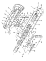
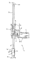
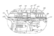
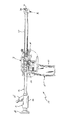
体組織を貫通すると同時に被貫通体組織を前方に見ることができる装置が提供されている。図1に示したような好ましい実施例において、装置は、オブトラトール組立体12とカニューレ組立体14と内視鏡16等の画像伝達部材16とを有する、トロカール組立体10を含む。内視鏡16は、被貫通体組織を観察するために、オブトラトール組立体12内に位置決めされる。ここで用いるオブトラトール組立体という用語は、トロカール組立体10の組織貫通組立体を指す。
図1及び図2を参照すると、オブトラトール組立体12は、ハウジング18と、長手方向に延びるオブトラトールスリーブ20とを含む。オブトラトールハウジング18は、胴部19と握り21とを含む。オブトラトールスリーブ20の近位端部は、オブトラトールスリーブ20がオブトラトールハウジング18から外側に延びるように、胴部19の溝22内に固定されている。握り21は、体組織の貫通を容易にすべく、把持のために設けられている。
オブトラトールスリーブ20は、近位端部と遠位端部との間で延びる長手方向内孔(ボア)24を有する。長手方向内孔24は、図1に示したように、内視鏡16の内視部26を収容するように、形成され且つ寸法決めされている。オブトラトール組立体12のハウジング18は、溶接、接着等により接合される2つの半部から構成される。図2に示すように、板ばね103は、ハウジング18の胴部19の近位端部に位置する溝105内に位置決めされている。板ばね103は、内視鏡16の内視部26と係合するために設けられ、内視鏡をオブトラトールスリーブ20に対して一定の長手方向関係で摩擦的に維持している。
【0007】
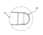
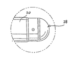
図2及び図3を参照すると、画像通過部材28は、オブトラトールスリーブ20の遠位端部に固定され、画像をオブトラトールスリーブ20内に案内すると共に照射光をオブトラトールスリーブ20から体組織まで伝送せしめるために設けられている。画像通過部材28は、種々の材料、例えばポリスチレン、ポリメチルメタクリレート(PMMA)、ポリウレタン、透明エポキシ樹脂及び/又はガラスその他の透明材料等から製造された、透明光学窓又は対物光学部材である。この好ましい実施例で示された光学窓は、半球形即ちドーム形であり、光学画像を透過してオブトラトールスリーブ20の長手方向内孔24内に導入し、内視鏡16の遠位端部に入射させることができる。
対物光学部材もまた、ドーム形部材である。しかしながら、この構成では、対物光学部材28のドーム形表面に入射する光学画像は、オブトラトールスリーブの長手方向内孔24内に案内され、内視鏡16の遠位端部に入射する。光学窓並びに対物光学部材は、好ましくは、前方の略全角度を見ることができるように、構成される。
再び図2を参照すると、オブトラトール組立体12の切断部32は、作動組立体36に接続された刃34を含む。好ましい実施例に示された刃34は、円弧形であり、ドーム形画像通過部材28の外表面に一致するようになっている。刃34は、非展延位置にあるとき、ドーム形画像通過部材28内の円弧状凹部内に収まるようになっている。刃34は、好ましくは、図示したように、画像通過部材の外表面に対して中心決めされている。従って、刃は、視覚上、体の観察を妨げないように中心を通る即ち視界を二分する細い線として現れる。
【0008】
ここで図2、図4、図5及び図6を参照すると、作動部材36は、ハウジング18内に含まれ、以下詳述するように非展延位置(図4)と展延位置(図6)との間で刃34を移動させるために設けられている。図2に示したように、作動部材36は、ハウジング18内の溝104内に摺動可能に位置決めされて非作動位置と作動位置との間で移動可能な、トリガ102を含む。図5に示したように、ハウジング18とトリガ102との間には、通常、非作動位置にトリガを付勢するように、ばね106が固定されている。トリガ102には、ハウジング18内の対応する溝110及び111内に延びる、整合フィンガ108及び109が形成されている。整合フィンガ108及び109は、ハウジング18の溝104内にトリガ102を整合維持するために設けられている。
トリガ102には、支柱114の形をしたラッチ解放部材を含む、ハンマラッチ112が固定されている。図5に示したように、支柱114は、二つのハウジング半部の間を延び、各ハウジング半部の対応する溝116内に入っている。以下詳述するように、溝116は、ハンマラッチ112をハンマと係合させる長手方向部分116aと、ハンマラッチ112をハンマから離脱させる傾斜部116bとを含む。
【0009】
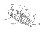
図2及び図5を参照すると、作動組立体36は、ハンマ120、ブッシュ122及び一対の駆動ばね124及び126等の、刃駆動部材も含む。図5に示したように、ハンマ、ブッシュ、及び駆動ばねは、オブトラトールスリーブ20と同軸的に整列している。駆動ばね124は、その一方の端部がハウジングと係合し他方の端部がハンマ120の近位端部と係合するように、各ハウジング半部の溝128内でオブトラトールスリーブ20の周囲に位置決めされている。駆動ばね124は、図5に矢印Aで示したように、通常、オブトラトール組立体12の遠位端部の方にハンマ120を付勢する。ブッシュ122の近位端部は、ハンマ120に隣接して位置決めされ、ブッシュ122の遠位端部は、駆動ばね126の一方の端部と係合する。図示したように、駆動ばね126の他方の端部は、ハウジング18と係合する。ブッシュ122からハウジング18内の溝125内に延びるフィンガ123は、ブッシュ122の近位及び遠位動作を、従って刃34の近位及び遠位動作を規制するために設けられている。
図2及び図7を参照すると、刃プッシャアーム38及び40が、オブトラトールスリーブ20内のスロット39及び41内にそれぞれ位置決めされている。図7に示すように、各刃プッシャアームの近位端部は、そこから外側に延びるフィンガ130を含み、該フィンガは、刃プッシャアーム38及び40をブッシュ122に取り外し可能に固定するために、ブッシュ122内の対応する切欠き132内で摺動するように構成されている。
【0010】
図8から図13を参照すると、上述した構成において、図8及び図9の矢印Bで示した近位方向のトリガ102の動作により、ハンマラッチ112がハンマ120を後退させ、駆動ばね124を圧縮する(即ち、ハンマラッチがハンマを打撃準備位置に移動させる)。支柱114は、溝116の長手方向部分116a内にあり、刃34は、図10に示すように、対物光学部材28内の非展延(即ち後退)位置に留まる。更にトリガ102を近位方向に移動させると、図11及び図12に示したように、支柱114が溝116の傾斜部116b内で下方に移動する。支柱114の下方への移動により、ハンマラッチ112はハンマ120から外れ、その結果ハンマ120は、駆動ばね124により遠位方向に(即ち矢印Cの方向に)押される。ハンマ120が遠位方向に移動すると、ハンマはブッシュ122と係合してブッシュを遠位方向に押し、刃34を図11及び図13に示したように展延(即ち露出)位置に移動させる。更に、ブッシュ122が遠位方向へ移動すると駆動ばね126が圧縮される。駆動ばね126の付勢力がハンマ120により加えられた圧縮力を上回ると、駆動ばね126は自動的にブッシュ124を近位方向に付勢し、刃34は自動的に非展延位置に復帰する。かくして、ハンマ120とブッシュ122の係合により、刃の実質的に瞬間的な展延と後退が行われ、刃は短時間露出状態に置かれる。従って、トリガが所定の位置に引かれると、刃は展延し、その後ユーザの別の動作を要することなく(即ち、トリガを更に移動させることなく)後退する。
【0011】
上述した構成において、作動組立体36は、2段階に動作する。第1の段階で、トリガ102を近位方向に移動してハンマ120をセットする。第2の段階では、トリガ102を更に近位方向に移動してハンマを自動的に遠位方向に移動させて刃34を展延位置に前進させ、更に、駆動ばね126の付勢力により非展延位置まで自動的に復帰させる。この2つの段階は、トリガ102を十分に引き搾ったときに、自動的に行われる。
図1を参照すると、カニューレ組立体14は、カニューレハウジング52と、該カニューレハウジング52に固定されてそこから外側に延びるカニューレスリーブ54とを含む。オブトラトールハウジング18の胴部19は、カニューレハウジング52の近位端部と嵌合するように構成され寸法決めされており、その結果、オブトラトールスリーブ20は、二つの組立体を嵌合すると、カニューレスリーブ54と同軸的に整合するようになっている。カニューレスリーブ54は、オブトラトール組立体12(及び内視鏡16)の貫通及びそれに続く除去後も体内に留まるように構成されており、適当な内視/腹腔器具を挿通可能としている。
【0012】
カニューレハウジング内の気密封止を維持するために、本発明のオブトラトール組立体12並びに他の内視外科用器具を収容するように構成された封止部材又は装置を、カニューレハウジング内に位置決めしてもよい。適当な封止装置の一例は、ダックビル封止部材を利用している。代表的なカニューレ組立体と封止装置のより詳細な説明は、出典を明記することによりその開示内容を本願明細書の一部とする、1993年1月19に発行された米国特許第5180373号に、記載されている。
引き続き図1を参照すると、内視鏡16は、内視部26と内視鏡ハウジング58とを含む。内視部26は、照射光を内視ハウジング58から内視部の遠位端部まで伝送して、手術箇所を照射するように構成されている。例示的構成において、内視部26は、外側シース60と、手術箇所を照射するために内視鏡ハウジング58の光源コネクタ64と外側シース60の遠位端部との間を延びる環状配列光ファイバ素子62とを含む。照射光を付与するために、任意の公知の光源をコネクタ64に接続してもよい。
内視部26は、内視鏡16の遠位端部で受光した光学画像を観察用の接眼レンズ68に移送するCCD、光ファイバ素子束又は対物群等から成る、画像伝送系66を含む。また、非貫通体組織のビデオ画像を得るために、モニタを含むビデオ装置をハウジング58に機能的に接続してもよい。
【0013】
好ましくは、光ファイバ素子62は、画像伝送系を取り囲むように、外側シースの内側壁に隣接して位置決めされる。この構成では、内視鏡からの照射光は、画像通過部材28を通過し、また画像通過部材28に入射する光学画像は、画像伝送系を介して接眼レンズ68に伝達される。利用可能な内視鏡の例は、出典を明記することによりその開示内容を本願明細書の一部とする、米国特許第4964710号に記載されている。
別の実施例では、オブトラトール組立体12及び内視鏡16又はその光学素子は、カニューレ組立体14内に挿入される単一のユニットとすることができる。例えば、オブトラトール組立体自体が手術箇所を照射してその画像をビデオモニタに伝送しながら組織を貫通し得るように、照射光学素子及び/又は撮像光学素子をオブトラトール組立体の中に組み込んで製造することができる。この例ではオブトラトール組立体は、長手方向内孔を有しないで、封止される。
手術に際しては、図4に示すように、内視鏡16をトロカール組立体10即ちオブトラトールスリーブ20の長手方向内孔24内に挿入する。
次に、外科医は、体組織に対して刃34を位置決めし、トリガ102を連続して引き搾ることにより刃34を反復的に移動させる。この結果、刃は、自動的に非展延位置から展延位置まで更に再び非展延位置に迅速に移動する。次に、体組織を貫通するために、握り21に対し遠位方向に圧力を加える。刃34の動作は、体組織の切開を制御可能に行うことを容易にし、外科医は、体組織を貫通するために比較的小さな圧力を握り21に加えるだけでよい。体組織の貫通中、外科医は接眼レンズ68を通してかかる貫通を観察するか、或いは例えばビデオ装置を利用した場合は公知のビデオモニタを介して体組織の貫通を観察すればよい。
【0014】
また、外科医は、貫通中、刃34をより選択的に展延してもよい。即ち、外科医は、トロカール組立体を挿入した後、筋肉等のより厚い組織に達するまで体組織を鈍く貫通する。この時点で、この厚い組織を貫通する(切開する)ために刃を展延する。厚い組織に再び遭遇した場合には、再び刃を展延することができる。体腔に挿入後、カニューレ組立体14から内視鏡16及びオブトラトール組立体12を除去する一方、カニューレ組立体14は所望の器具を挿入するために体内に残しておく。
本発明の精神及び範囲から逸脱することなくここに開示した実施例に種々の変形を施し得ることは理解されよう。例えば、種々の直径の内視鏡同様、カニューレ組立体、オブトラトール組立体に対して様々な直径が考えられる。また、刃の瞬間的な展延及び後退を達成するために、トリガ組立体の構成に種々の変形を施してもよい。従って、上述した説明は、限定的なものではなく、好ましい実施例の単なる例示と解釈されるべきである。当業者は、前記特許請求の範囲内で他の変形例を想到し得よう。
【図面の簡単な説明】
【図1】カニューレ組立体とオブトラトール組立体と内視鏡とから成る、光学トロカールの分解斜視図。
【図2】刃を展延するためのトリガ組立体を示した、図1のオブトラトール組立体の部分分解図。
【図3】図1のオブトラトール組立体の遠位端部の断面図であって、その遠位端部に位置決めされた対物光学部材を示した図。
【図4】トリガ組立体を示した、図1のオブトラトール組立体と内視鏡の部分断面側面図。
【図5】非作動位置にあるトリガを示した、図4の装置のトリガ組立体のEの部分の拡大側面図。
【図6】刃プッシャアームと刃との間の接続を示した、図2のオブトラトール組立体の遠位端部Fの拡大組立図。
【図7】トリガ組立体への刃プッシャアームの接続を示した、図2のトリガ組立体のGの部分の部分断面組立図。
【図8】非展延位置にある刃と共にトリガ組立体の部分作動を示す、図1のオブトラトール組立体と内視鏡の部分断面側面図。
【図9】図8のトリガ組立体のHの部分の拡大側面図。
【図10】非展延位置にある刃と共にドーム形の対物光学部材を示す、図8のオブトラトール組立体の遠位端部Iの拡大図。
【図11】展延位置にある刃と共にトリガ組立体の作動を示す、図1のオブトラトール組立体と内視鏡の部分断面側面図。
【図12】図11のトリガ組立体のJの部分の拡大側面図。
【図13】展延位置にある刃と共にドーム形の対物光学部材を示す、図11のオブトラトール組立体の遠位端部Kの拡大図。[0001]
[Industrial application fields]
The present invention relates to an apparatus for penetrating a body tissue and observing the penetration state, and in particular, has a blade that reciprocates in response to an operation of a trigger mechanism to directly penetrate a peritoneum or other body tissues by observation An optical trocar assembly that facilitates.
[0002]
[Prior art and problems to be solved by the invention]
Endoscopic surgery, i.e., surgery performed through a tubular sleeve or cannula, has been utilized for many years. Initially, endoscopic surgical procedures were primarily diagnostic in nature. As endoscopic technology has advanced in recent years, surgeons have gradually become more complex and innovative endoscopic surgical procedures. In endoscopic procedures, surgery is performed in a hollow internal body of the body through a small incision or through a thin endoscopic tube (cannula) inserted through a small wound in the skin. In laparoscopic procedures, surgery is performed inside the abdominal cavity.
Laparoscopic procedures typically use instruments that are sealed on the inside to prevent gas from entering and exiting the body through a laparoscope or endoscope cut. This is especially true for surgical procedures where the surgical site is vented. In addition, laparoscopic and endoscopic procedures often require surgeons to act on organs, tissues, and blood vessels far from the incision, and thus the instruments used for such procedures are only capable of remote surgery. Must have sufficient dimensions and length. Typically, a trocar is used that includes a cannula that is used in place during an endoscopic procedure to penetrate the body cavity after ventilating the surgical site. In general, trocars used throughout such procedures include a stylet having a sharp point for penetrating a body cavity, positioned coaxially within a protective tube to prevent the patient or surgeon from accidentally touching the point. An example of a known trocar is described in US Pat. No. 4,601,710 awarded to Mol and assigned to a common assignee. The most commonly used trocar uses a protective tube or relatively retracts the tip to prevent accidental contact with tissue.
[0003]
Therefore, it would be convenient to provide a trocar assembly that can observe penetration of the peritoneum and other body parts. The trocar assembly described herein provides an improved objective optical member for passing an optical image toward an imaging system and for selectively reciprocating a blade that facilitates penetration of body tissue. An improved trigger mechanism is provided. This objective optical member, in combination with an imaging system, provides a clear and bright image of the penetrated body tissue as well as the entering body cavity.
[0004]
[Means for Solving the Problems]
A blade actuation assembly is provided that is capable of selectively extending a tissue cutting blade positioned at a distal end of an optical trocar assembly configured to penetrate body tissue by direct observation. The blade actuation assembly includes at least one blade pusher member attached to the obturator sleeve and is connected to the blade pusher member so that the blade can be alternately moved between the extended position and the non-expanded position. A configured blade drive mechanism. A blade drive latch is provided to facilitate movement of the blade drive mechanism to the preparation position and to maintain the blade drive mechanism releasably in the preparation position. The blade actuation assembly also includes a trigger operatively connected to the blade drive latch and movable relative to the blade drive mechanism. In this configuration, when the trigger is moved by the first predetermined distance, the blade driving latch moves the blade driving mechanism to the preparation position, and when the trigger is moved by the second predetermined distance, the blade driving latch is moved by the blade driving mechanism. And the blade drive mechanism is retracted and the blade for cutting tissue is retracted to a retracted position within the distal end of the optical trocar assembly.
The trocar described herein includes a cannula assembly, an obturator assembly, and an image transmission system. The cannula assembly includes a cannula housing and a cannula sleeve extending from the cannula housing. The obturator assembly has a proximal end, a distal end and a longitudinal bore (bore) extending therebetween and configured to coaxially align with the cannula assembly. including.
[0005]
An image passing member or objective optical member is positioned at the distal end of the obturator sleeve and is provided to pass the optical image towards the longitudinal bore and to pass the illuminating light towards the body tissue. ing.
In a preferred embodiment, the objective optical member is a generally hemispherical or dome-shaped optical window for inputting an optical image. The objective optical member is a dome-shaped lens that inputs an optical image and guides it to the obturator sleeve. A hemispherical or dome-shaped optical window is advantageous in that it does not damage tissue.
An image transmission member, such as an endoscope, is preferably removably positioned within the longitudinal bore of the obturator sleeve and transmits the illumination light through the image passing member to the surgical site while An optical image from the passing member is provided for transmission to the proximal end of the obturator housing for subsequent viewing by the surgeon.
An actuation mechanism is provided for moving the blade at the distal end of the obturator sleeve. The actuation mechanism includes a blade advancement mechanism that is operatively connected to the blade and configured to move the blade between a non-expanded position and a extended position. The actuating mechanism also includes a trigger mechanism having at least one trigger operatively connected to the blade advancement mechanism and movable between a non-actuated position and an actuated position. In this configuration, when the trigger moves to the operating position, the blade advance mechanism moves the blade to the extended position. The blade advancement mechanism includes a hammer, a bush, and a drive spring, which, when the trigger moves to the operating position, causes the drive spring to move the hammer and bush distally to move the blade to the extended position. It is configured.
[0006]
【Example】
Hereinafter, preferred embodiments of the present invention will be described in detail with reference to the accompanying drawings.
There has been provided an apparatus capable of penetrating body tissue and simultaneously seeing through the body tissue. In a preferred embodiment as shown in FIG. 1, the apparatus includes a
With reference to FIGS. 1 and 2, the obturator assembly 12 includes a
The
[0007]
Referring to FIGS. 2 and 3, the
The objective optical member is also a dome-shaped member. However, in this configuration, the optical image incident on the dome-shaped surface of the objective
Referring again to FIG. 2, the cutting portion 32 of the obturator assembly 12 includes a
[0008]
Referring now to FIGS. 2, 4, 5 and 6, the actuating
Fixed to the
[0009]
With reference to FIGS. 2 and 5, the
Referring to FIGS. 2 and 7,
[0010]
Referring to FIGS. 8-13, in the configuration described above, the action of the
[0011]
In the configuration described above, the
Referring to FIG. 1,
[0012]
To maintain a hermetic seal within the cannula housing, a sealing member or device configured to receive the obturator assembly 12 of the present invention as well as other endoscopic surgical instruments is positioned within the cannula housing. Also good. An example of a suitable sealing device utilizes a duckbill sealing member. A more detailed description of an exemplary cannula assembly and sealing device is provided in US Pat. No. 5,180,373, issued Jan. 19, 1993, the disclosure of which is hereby incorporated by reference. It is described in.
With continued reference to FIG. 1, the
The
[0013]
Preferably, the optical fiber element 62 is positioned adjacent to the inner wall of the outer sheath so as to surround the image transmission system. In this configuration, the irradiation light from the endoscope passes through the
In another example, the obturator assembly 12 and the
In the operation, as shown in FIG. 4, the
The surgeon then positions the
[0014]
The surgeon may also more selectively spread the
It will be understood that various modifications may be made to the embodiments disclosed herein without departing from the spirit and scope of the invention. For example, various diameters are contemplated for cannula and obturator assemblies as well as endoscopes of various diameters. Also, various modifications may be made to the construction of the trigger assembly to achieve instantaneous blade extension and retraction. Therefore, the above description should not be construed as limiting, but merely as exemplifications of preferred embodiments. Those skilled in the art will envision other modifications within the scope of the claims.
[Brief description of the drawings]
FIG. 1 is an exploded perspective view of an optical trocar comprising a cannula assembly, an obturator assembly and an endoscope.
FIG. 2 is a partially exploded view of the obturator assembly of FIG. 1 showing a trigger assembly for extending the blade.
3 is a cross-sectional view of the distal end of the obturator assembly of FIG. 1, showing the objective optical member positioned at the distal end.
4 is a partial cross-sectional side view of the obturator assembly and endoscope of FIG. 1 showing the trigger assembly. FIG.
5 is an enlarged side view of portion E of the trigger assembly of the apparatus of FIG. 4 showing the trigger in a non-actuated position.
6 is an enlarged assembly view of the distal end F of the obturator assembly of FIG. 2 showing the connection between the blade pusher arm and the blade.
7 is a partial cross-sectional assembly view of portion G of the trigger assembly of FIG. 2 showing the connection of the blade pusher arm to the trigger assembly.
8 is a partial cross-sectional side view of the obturator assembly and endoscope of FIG. 1 showing partial actuation of the trigger assembly with the blade in a non-deployed position. FIG.
9 is an enlarged side view of portion H of the trigger assembly of FIG. 8. FIG.
10 is an enlarged view of the distal end I of the obturator assembly of FIG. 8 showing the dome-shaped objective optical member with the blade in a non-deployed position.
FIG. 11 is a partial cross-sectional side view of the obturator assembly and endoscope of FIG. 1 illustrating the operation of the trigger assembly with the blade in the extended position.
12 is an enlarged side view of a portion J of the trigger assembly of FIG. 11. FIG.
13 is an enlarged view of the distal end K of the obturator assembly of FIG. 11 showing the dome-shaped objective optical member with the blade in the extended position.
Claims (14)
前記カニューレの前記内孔内に取り外し可能に位置決めされて対物光学部材を有するオブトラトールと、
前記オブトラトールの遠位端部に移動可能に位置決めされた刃と、
前記刃に接続された作動機構と、
を備え、
前記作動機構が、第1及び第2の位置の間で移動可能であり、前記第1の位置から前記第2の位置までの前記作動機構の移動により、前記刃を後退位置から展延位置へ、更に再び後退位置へ移動させる、
ことを特徴とする体組織を貫通するための装置。A cannula having a longitudinal bore;
An obturator removably positioned within the inner bore of the cannula and having an objective optical member;
A blade movably positioned at a distal end of the obturator;
An actuation mechanism connected to the blade;
With
The actuating mechanism is movable between a first position and a second position, and movement of the actuating mechanism from the first position to the second position moves the blade from the retracted position to the extended position. , Move it to the reverse position again,
A device for penetrating body tissue, characterized in that.
ことを特徴とする請求項1記載の装置。The actuating mechanism includes a trigger connected to a blade advancement mechanism, the mechanisms configured to reciprocate the blade between the retracted position and the extended position;
The apparatus according to claim 1.
前記対物光学部材を通過した画像を、観察用に前記オブトラトールの近位端部に伝送するために、前記オブトラトール内に及び前記対物光学部材と隣接して位置決めされた画像伝送部材を備えた、
ことを特徴とする請求項1記載の装置。Furthermore,
An image transmission member positioned in the obturator and adjacent to the objective optical member for transmitting an image that has passed through the objective optical member to the proximal end of the obturator for observation;
The apparatus according to claim 1.
ことを特徴とする請求項1〜3のいずれか1項記載の装置。The image transmission member includes an endoscope removably positioned within a longitudinal bore in the obturator;
An apparatus according to any one of claims 1 to 3, characterized in that
ことを特徴とする前記請求項の1〜4のいずれか1項記載の装置。The objective optical member has a dome-shaped outer surface;
An apparatus according to any one of claims 1 to 4, characterized in that
ことを特徴とする請求項5記載の装置。The blade is arcuate to coincide with the dome-shaped outer surface of the objective optical member;
6. The apparatus of claim 5, wherein:
近位及び遠位端部を有して長手方向に移動可能な少なくとも1つの刃プッシャ部材と、
前記少なくとも1つの刃プッシャ部材の前記近位端部に接続されて、展延及び非展延位置との間で刃を交互に移動させるように構成された、刃駆動機構と、
準備位置への前記刃駆動機構の移動を容易にすると共に、前記準備位置内で前記刃駆動機構を解放可能に維持するように構成された、刃駆動ラッチと、
前記刃駆動ラッチに機能的に接続されたトリガであって、前記トリガが第1の所定の距離だけ移動すると前記刃駆動ラッチが前記刃駆動機構を前記準備位置まで移動させ、前記トリガが第2の所定の距離だけ移動すると前記刃駆動ラッチを前記刃駆動機構から解放して前記刃駆動機構を作動させるように、前記刃駆動機構に対して移動可能なトリガと、
を有する、
ことを特徴とする前記請求項1〜6のいずれか1項記載の装置。The operating mechanism is
At least one blade pusher member having proximal and distal ends and longitudinally movable;
A blade drive mechanism connected to the proximal end of the at least one blade pusher member and configured to alternately move the blade between extended and non-extended positions;
A blade drive latch configured to facilitate movement of the blade drive mechanism to a preparation position and to releasably maintain the blade drive mechanism within the preparation position;
A trigger operatively connected to the blade drive latch, wherein when the trigger moves a first predetermined distance, the blade drive latch moves the blade drive mechanism to the ready position, and the trigger is a second A trigger movable relative to the blade drive mechanism so as to release the blade drive latch from the blade drive mechanism and actuate the blade drive mechanism when moved by a predetermined distance;
Having
The apparatus according to any one of claims 1 to 6, characterized in that:
第1の段階では、前記トリガの作動により、前記刃前進機構が準備位置まで移動し、
第2の段階では、前記トリガの前記作動位置への移動時に、前記刃前進機構が前記準備位置から解放される、
ことを特徴とする前記請求項1〜7のいずれか1項に記載の装置。The actuating mechanism performs a two-stage operation to spread the blade;
In the first stage, the operation of the trigger moves the blade advance mechanism to a preparation position,
In a second stage, when the trigger moves to the operating position, the blade advancement mechanism is released from the preparation position;
The device according to claim 1, wherein the device is a device.
近位端部と遠位端部と長手方向内孔とを有する、スリーブと、
前記光学画像を集束させて前記長手方向内孔内に伝送するために、前記スリーブの前記遠位端部に位置決めされた、ドーム形対物光学部材と、
前記対物光学部材内の凹部内に取り付けられ、展延位置と非展延位置との間で移動可能な、刃と、
を備えた、
ことを特徴とするオブトラトール。An obturator for facilitating insertion into body tissue by direct observation,
A sleeve having a proximal end, a distal end and a longitudinal bore;
A dome-shaped objective optical member positioned at the distal end of the sleeve for focusing and transmitting the optical image into the longitudinal bore;
A blade mounted in a recess in the objective optical member and movable between an extended position and a non-extended position;
With
Obtrator is characterized by that.
ことを特徴とする請求項9記載のオブトラトール。The objective optical member is an optical window;
The obturator according to claim 9.
ことを特徴とする請求項10記載のオブトラトール。The objective optical member is an optical lens;
The obturator according to claim 10.
前記展延位置と非展延位置との間で前記刃を選択的に往復動させるために、前記刃に機能的に接続された作動機構を備えた、
ことを特徴とする請求項9記載のオブトラトール。Furthermore,
An actuating mechanism operatively connected to the blade to selectively reciprocate the blade between the extended position and the non-extended position;
The obturator according to claim 9.
前記長手方向内孔内に伝送された画像を前記スリーブの前記近位端部に伝送するために、前記スリーブの前記長手方向内孔内に少なくとも部分的に位置決めされ且つ前記対物光学部材に隣接した画像伝送部材を備えた、
ことを特徴とする請求項9記載のオブトラトール。Furthermore,
Positioned at least partially within the longitudinal bore of the sleeve and adjacent to the objective optical member for transmitting an image transmitted within the longitudinal bore to the proximal end of the sleeve With an image transmission member,
The obturator according to claim 9.
ことを特徴とする請求項13記載のオブトラトール。The image transmission member has an endoscope positioned movably in the longitudinal bore;
The obturator according to claim 13.
Applications Claiming Priority (2)
| Application Number | Priority Date | Filing Date | Title |
|---|---|---|---|
| US24970794A | 1994-05-26 | 1994-05-26 | |
| US08/249707 | 1994-05-26 |
Publications (2)
| Publication Number | Publication Date |
|---|---|
| JPH0847477A JPH0847477A (en) | 1996-02-20 |
| JP3672618B2 true JP3672618B2 (en) | 2005-07-20 |
Family
ID=22944639
Family Applications (1)
| Application Number | Title | Priority Date | Filing Date |
|---|---|---|---|
| JP12792695A Expired - Fee Related JP3672618B2 (en) | 1994-05-26 | 1995-05-26 | Optical trocar |
Country Status (7)
| Country | Link |
|---|---|
| US (1) | US5860996A (en) |
| EP (1) | EP0684016B1 (en) |
| JP (1) | JP3672618B2 (en) |
| AU (1) | AU691900B2 (en) |
| CA (1) | CA2149290C (en) |
| DE (1) | DE69513563T2 (en) |
| ES (1) | ES2139116T3 (en) |
Families Citing this family (203)
| Publication number | Priority date | Publication date | Assignee | Title |
|---|---|---|---|---|
| DE19547246C1 (en) * | 1995-12-18 | 1997-03-20 | Riek Siegfried | Medicinal needle containing spring-loaded guard |
| US6006134A (en) * | 1998-04-30 | 1999-12-21 | Medtronic, Inc. | Method and device for electronically controlling the beating of a heart using venous electrical stimulation of nerve fibers |
| DE19626408A1 (en) * | 1996-07-01 | 1998-01-08 | Berchtold Gmbh & Co Geb | Trocar for laparoscopic operations |
| DE19646542C2 (en) * | 1996-10-31 | 2001-11-08 | Gert Otten | Interchangeable trocar mandrel |
| US7018406B2 (en) * | 1999-11-17 | 2006-03-28 | Corevalve Sa | Prosthetic valve for transluminal delivery |
| US8579966B2 (en) * | 1999-11-17 | 2013-11-12 | Medtronic Corevalve Llc | Prosthetic valve for transluminal delivery |
| US20070043435A1 (en) * | 1999-11-17 | 2007-02-22 | Jacques Seguin | Non-cylindrical prosthetic valve system for transluminal delivery |
| US6319266B1 (en) * | 2000-03-16 | 2001-11-20 | United States Surgical Corporation | Trocar system and method of use |
| ATE396648T1 (en) * | 2000-05-09 | 2008-06-15 | Paieon Inc | SYSTEM AND METHOD FOR THREE-DIMENTIONAL RECONSTRUCTION OF AN ARTERY |
| US20020161387A1 (en) * | 2000-06-22 | 2002-10-31 | Blanco Ernesto E. | Safety trocar with progressive cutting tip guards and gas jet tissue deflector |
| WO2002005888A1 (en) * | 2000-06-30 | 2002-01-24 | Viacor Incorporated | Intravascular filter with debris entrapment mechanism |
| DE10037421C2 (en) * | 2000-07-21 | 2003-06-26 | Leonid Sverdlov | Device for minimally invasive access to the organs of the abdominal cavity |
| ES2334841T3 (en) * | 2000-08-08 | 2010-03-16 | Tyco Healthcare Group Lp | MOLDED TROCAR LATCH. |
| AU2001285078A1 (en) | 2000-08-18 | 2002-03-04 | Atritech, Inc. | Expandable implant devices for filtering blood flow from atrial appendages |
| US7544206B2 (en) * | 2001-06-29 | 2009-06-09 | Medtronic, Inc. | Method and apparatus for resecting and replacing an aortic valve |
| FR2826863B1 (en) * | 2001-07-04 | 2003-09-26 | Jacques Seguin | ASSEMBLY FOR PLACING A PROSTHETIC VALVE IN A BODY CONDUIT |
| FR2828091B1 (en) | 2001-07-31 | 2003-11-21 | Seguin Jacques | ASSEMBLY ALLOWING THE PLACEMENT OF A PROTHETIC VALVE IN A BODY DUCT |
| US7097659B2 (en) * | 2001-09-07 | 2006-08-29 | Medtronic, Inc. | Fixation band for affixing a prosthetic heart valve to tissue |
| EP1429660B1 (en) | 2001-09-24 | 2013-06-05 | Applied Medical Resources Corporation | Bladeless obturator |
| US8721713B2 (en) * | 2002-04-23 | 2014-05-13 | Medtronic, Inc. | System for implanting a replacement valve |
| US7758603B2 (en) | 2002-05-16 | 2010-07-20 | Applied Medical Resources Corporation | Blunt tip obturator |
| US7056329B2 (en) * | 2002-10-23 | 2006-06-06 | Intellimed Surgical Solutions, Llc | Laparoscopic direct vision dissecting port |
| US20040093000A1 (en) * | 2002-10-23 | 2004-05-13 | Stephen Kerr | Direct vision port site dissector |
| US7393339B2 (en) * | 2003-02-21 | 2008-07-01 | C. R. Bard, Inc. | Multi-lumen catheter with separate distal tips |
| US7854724B2 (en) | 2003-04-08 | 2010-12-21 | Surgiquest, Inc. | Trocar assembly with pneumatic sealing |
| CA2540682A1 (en) | 2003-10-03 | 2005-04-14 | Applied Medical Resources Corporation | Bladeless optical obturator |
| US7186265B2 (en) * | 2003-12-10 | 2007-03-06 | Medtronic, Inc. | Prosthetic cardiac valves and systems and methods for implanting thereof |
| US8579962B2 (en) * | 2003-12-23 | 2013-11-12 | Sadra Medical, Inc. | Methods and apparatus for performing valvuloplasty |
| US20050137686A1 (en) * | 2003-12-23 | 2005-06-23 | Sadra Medical, A Delaware Corporation | Externally expandable heart valve anchor and method |
| US8840663B2 (en) * | 2003-12-23 | 2014-09-23 | Sadra Medical, Inc. | Repositionable heart valve method |
| US8603160B2 (en) | 2003-12-23 | 2013-12-10 | Sadra Medical, Inc. | Method of using a retrievable heart valve anchor with a sheath |
| US20050137696A1 (en) * | 2003-12-23 | 2005-06-23 | Sadra Medical | Apparatus and methods for protecting against embolization during endovascular heart valve replacement |
| US20120041550A1 (en) | 2003-12-23 | 2012-02-16 | Sadra Medical, Inc. | Methods and Apparatus for Endovascular Heart Valve Replacement Comprising Tissue Grasping Elements |
| US7959666B2 (en) | 2003-12-23 | 2011-06-14 | Sadra Medical, Inc. | Methods and apparatus for endovascularly replacing a heart valve |
| US8287584B2 (en) * | 2005-11-14 | 2012-10-16 | Sadra Medical, Inc. | Medical implant deployment tool |
| US9526609B2 (en) * | 2003-12-23 | 2016-12-27 | Boston Scientific Scimed, Inc. | Methods and apparatus for endovascularly replacing a patient's heart valve |
| US7381219B2 (en) | 2003-12-23 | 2008-06-03 | Sadra Medical, Inc. | Low profile heart valve and delivery system |
| US7329279B2 (en) * | 2003-12-23 | 2008-02-12 | Sadra Medical, Inc. | Methods and apparatus for endovascularly replacing a patient's heart valve |
| US7445631B2 (en) * | 2003-12-23 | 2008-11-04 | Sadra Medical, Inc. | Methods and apparatus for endovascularly replacing a patient's heart valve |
| US8343213B2 (en) | 2003-12-23 | 2013-01-01 | Sadra Medical, Inc. | Leaflet engagement elements and methods for use thereof |
| US8182528B2 (en) * | 2003-12-23 | 2012-05-22 | Sadra Medical, Inc. | Locking heart valve anchor |
| US11278398B2 (en) | 2003-12-23 | 2022-03-22 | Boston Scientific Scimed, Inc. | Methods and apparatus for endovascular heart valve replacement comprising tissue grasping elements |
| US9005273B2 (en) * | 2003-12-23 | 2015-04-14 | Sadra Medical, Inc. | Assessing the location and performance of replacement heart valves |
| US20050137691A1 (en) * | 2003-12-23 | 2005-06-23 | Sadra Medical | Two piece heart valve and anchor |
| US7780725B2 (en) * | 2004-06-16 | 2010-08-24 | Sadra Medical, Inc. | Everting heart valve |
| US8828078B2 (en) * | 2003-12-23 | 2014-09-09 | Sadra Medical, Inc. | Methods and apparatus for endovascular heart valve replacement comprising tissue grasping elements |
| EP2529698B1 (en) * | 2003-12-23 | 2014-01-29 | Sadra Medical, Inc. | Repositionable heart valve |
| US7748389B2 (en) * | 2003-12-23 | 2010-07-06 | Sadra Medical, Inc. | Leaflet engagement elements and methods for use thereof |
| US20050137694A1 (en) | 2003-12-23 | 2005-06-23 | Haug Ulrich R. | Methods and apparatus for endovascularly replacing a patient's heart valve |
| ITTO20040135A1 (en) | 2004-03-03 | 2004-06-03 | Sorin Biomedica Cardio Spa | CARDIAC VALVE PROSTHESIS |
| EP2545870B1 (en) | 2004-06-29 | 2015-11-04 | Applied Medical Resources Corporation | Insufflating optical surgical instrument |
| US20060052867A1 (en) | 2004-09-07 | 2006-03-09 | Medtronic, Inc | Replacement prosthetic heart valve, system and method of implant |
| WO2006050225A2 (en) * | 2004-10-28 | 2006-05-11 | Strategic Technology Assessment Group | Apparatus and methods for performing brain surgery |
| US9265523B2 (en) | 2011-10-24 | 2016-02-23 | Nico Corporation | Surgical access system with navigation element and method of using same |
| US9216015B2 (en) | 2004-10-28 | 2015-12-22 | Vycor Medical, Inc. | Apparatus and methods for performing brain surgery |
| US9770261B2 (en) | 2004-10-28 | 2017-09-26 | Nico Corporation | Surgical access assembly and method of using same |
| US9387010B2 (en) | 2004-10-28 | 2016-07-12 | Nico Corporation | Surgical access assembly and method of using same |
| US9161820B2 (en) | 2004-10-28 | 2015-10-20 | Nico Corporation | Surgical access assembly and method of using same |
| US20080109026A1 (en) * | 2004-10-28 | 2008-05-08 | Strategic Technology Assessment Group | Apparatus and Methods for Performing Brain Surgery |
| US9186175B2 (en) | 2004-10-28 | 2015-11-17 | Nico Corporation | Surgical access assembly and method of using same |
| EP1830747A2 (en) * | 2004-11-19 | 2007-09-12 | Medtronic, Inc. | Method and apparatus for treatment of cardiac valves |
| WO2006065271A2 (en) * | 2004-12-15 | 2006-06-22 | Embo-Optics, Llc | Point of infusion lighting device |
| DE102005003632A1 (en) | 2005-01-20 | 2006-08-17 | Fraunhofer-Gesellschaft zur Förderung der angewandten Forschung e.V. | Catheter for the transvascular implantation of heart valve prostheses |
| US8070767B2 (en) * | 2005-01-28 | 2011-12-06 | Tyco Healthcare Group Lp | Optical penetrating adapter for surgical portal |
| ITTO20050074A1 (en) | 2005-02-10 | 2006-08-11 | Sorin Biomedica Cardio Srl | CARDIAC VALVE PROSTHESIS |
| US7470230B2 (en) | 2005-03-31 | 2008-12-30 | Tyco Healthcare Group Lp | Optical obturator |
| US7824327B2 (en) * | 2005-04-12 | 2010-11-02 | Tyco Healthcare Group Llp | Optical trocar with scope holding assembly |
| US7914569B2 (en) | 2005-05-13 | 2011-03-29 | Medtronics Corevalve Llc | Heart valve prosthesis and methods of manufacture and use |
| US20060287583A1 (en) * | 2005-06-17 | 2006-12-21 | Pool Cover Corporation | Surgical access instruments for use with delicate tissues |
| US7988670B2 (en) | 2005-06-30 | 2011-08-02 | Tyco Healthcare Group Lp | Trocar assembly with rotatable obturator housing |
| US20070005087A1 (en) * | 2005-06-30 | 2007-01-04 | Smith Robert C | Thin bladed obturator with curved surfaces |
| US7569071B2 (en) | 2005-09-21 | 2009-08-04 | Boston Scientific Scimed, Inc. | Venous valve, system, and method with sinus pocket |
| US8430851B2 (en) | 2005-10-14 | 2013-04-30 | Applied Medical Resources Corporation | Surgical access port |
| US20070213813A1 (en) | 2005-12-22 | 2007-09-13 | Symetis Sa | Stent-valves for valve replacement and associated methods and systems for surgery |
| US9078781B2 (en) * | 2006-01-11 | 2015-07-14 | Medtronic, Inc. | Sterile cover for compressible stents used in percutaneous device delivery systems |
| EP1988851A2 (en) | 2006-02-14 | 2008-11-12 | Sadra Medical, Inc. | Systems and methods for delivering a medical implant |
| DE102006015690A1 (en) | 2006-03-27 | 2007-10-11 | Aesculap Ag & Co. Kg | Surgical sealing element, surgical seal and surgical sealing system |
| EP2004095B1 (en) * | 2006-03-28 | 2019-06-12 | Medtronic, Inc. | Prosthetic cardiac valve formed from pericardium material and methods of making same |
| US7740655B2 (en) * | 2006-04-06 | 2010-06-22 | Medtronic Vascular, Inc. | Reinforced surgical conduit for implantation of a stented valve therein |
| US7524331B2 (en) * | 2006-04-06 | 2009-04-28 | Medtronic Vascular, Inc. | Catheter delivered valve having a barrier to provide an enhanced seal |
| US20070239269A1 (en) * | 2006-04-07 | 2007-10-11 | Medtronic Vascular, Inc. | Stented Valve Having Dull Struts |
| US20070239271A1 (en) * | 2006-04-10 | 2007-10-11 | Than Nguyen | Systems and methods for loading a prosthesis onto a minimally invasive delivery system |
| US20070244544A1 (en) * | 2006-04-14 | 2007-10-18 | Medtronic Vascular, Inc. | Seal for Enhanced Stented Valve Fixation |
| US20070244545A1 (en) * | 2006-04-14 | 2007-10-18 | Medtronic Vascular, Inc. | Prosthetic Conduit With Radiopaque Symmetry Indicators |
| US20070244546A1 (en) * | 2006-04-18 | 2007-10-18 | Medtronic Vascular, Inc. | Stent Foundation for Placement of a Stented Valve |
| US20080177295A1 (en) * | 2006-06-29 | 2008-07-24 | Dario Vitali | Surgical device having trocar and associated methods |
| EP1875874B1 (en) * | 2006-07-06 | 2013-02-27 | Covidien LP | Two mode trocar assembly |
| US11304800B2 (en) | 2006-09-19 | 2022-04-19 | Medtronic Ventor Technologies Ltd. | Sinus-engaging valve fixation member |
| US8876895B2 (en) * | 2006-09-19 | 2014-11-04 | Medtronic Ventor Technologies Ltd. | Valve fixation member having engagement arms |
| US8834564B2 (en) | 2006-09-19 | 2014-09-16 | Medtronic, Inc. | Sinus-engaging valve fixation member |
| WO2008045316A2 (en) * | 2006-10-06 | 2008-04-17 | Surgiquest, Incorporated | Visualization trocar |
| AU2007303069B2 (en) | 2006-10-06 | 2013-03-21 | Applied Medical Resources Corporation | Visual insufflation port |
| US8795223B2 (en) | 2011-03-08 | 2014-08-05 | Surgiquest, Inc. | Trocar assembly with pneumatic sealing |
| EP2101660A4 (en) * | 2006-12-15 | 2012-12-19 | Tyco Healthcare | Trocar assembly with obturator design |
| AU2007338691B2 (en) * | 2006-12-20 | 2013-07-04 | Covidien Lp | Surgical visual obturator |
| GB0625936D0 (en) * | 2006-12-28 | 2007-02-07 | Thermoteknix Systems Ltd | Correction of non-uniformity of response in sensor arrays |
| US20110040149A1 (en) * | 2007-01-12 | 2011-02-17 | Smith Robert C | Obturator assembly |
| US8246677B2 (en) * | 2007-02-16 | 2012-08-21 | Medtronic, Inc. | Delivery systems and methods of implantation for replacement prosthetic heart valves |
| AU2008219113B2 (en) | 2007-02-20 | 2013-05-09 | Covidien Lp | Surgical apparatus with annular penetrator |
| WO2008127887A1 (en) * | 2007-04-11 | 2008-10-23 | Tyco Healthcare Group Lp | Visualized entry trocar with moving blade |
| US7896915B2 (en) | 2007-04-13 | 2011-03-01 | Jenavalve Technology, Inc. | Medical device for treating a heart valve insufficiency |
| CA2683968A1 (en) | 2007-04-17 | 2008-10-30 | Tyco Healthcare Group Lp | Visual obturator with handle |
| CA2682696A1 (en) * | 2007-04-18 | 2008-10-30 | Tyco Healthcare Group Lp | Trocar assembly with obturator dissector |
| JP5340638B2 (en) * | 2007-05-22 | 2013-11-13 | コヴィディエン リミテッド パートナーシップ | Access sheath with blade |
| AU2008202266B2 (en) * | 2007-06-01 | 2013-09-12 | Covidien Lp | Obturator tips |
| US20080319467A1 (en) * | 2007-06-22 | 2008-12-25 | Thomas Wenchell | Thin bladed obturator |
| US8747458B2 (en) * | 2007-08-20 | 2014-06-10 | Medtronic Ventor Technologies Ltd. | Stent loading tool and method for use thereof |
| AU2008229774B2 (en) | 2007-10-05 | 2013-05-16 | Covidien Lp | Two-mode bladeless trocar assembly |
| USD663838S1 (en) | 2007-10-05 | 2012-07-17 | Surgiquest, Inc. | Visualization trocar |
| USD667954S1 (en) | 2007-10-05 | 2012-09-25 | Surgiquest, Inc. | Visualization trocar |
| US8282663B2 (en) | 2007-10-05 | 2012-10-09 | Tyco Healthcare Group Lp | Bladeless obturator for use in a surgical trocar assembly |
| US8192353B2 (en) * | 2007-10-05 | 2012-06-05 | Tyco Healthcare Group Lp | Visual obturator |
| US20090138079A1 (en) * | 2007-10-10 | 2009-05-28 | Vector Technologies Ltd. | Prosthetic heart valve for transfemoral delivery |
| US9848981B2 (en) | 2007-10-12 | 2017-12-26 | Mayo Foundation For Medical Education And Research | Expandable valve prosthesis with sealing mechanism |
| US9402643B2 (en) | 2008-01-15 | 2016-08-02 | Novartis Ag | Targeted illumination for surgical instrument |
| US9149358B2 (en) * | 2008-01-24 | 2015-10-06 | Medtronic, Inc. | Delivery systems for prosthetic heart valves |
| US20090287290A1 (en) * | 2008-01-24 | 2009-11-19 | Medtronic, Inc. | Delivery Systems and Methods of Implantation for Prosthetic Heart Valves |
| US8157853B2 (en) | 2008-01-24 | 2012-04-17 | Medtronic, Inc. | Delivery systems and methods of implantation for prosthetic heart valves |
| WO2009094197A1 (en) * | 2008-01-24 | 2009-07-30 | Medtronic, Inc. | Stents for prosthetic heart valves |
| CA2714062A1 (en) | 2008-01-24 | 2009-07-30 | Medtronic, Inc. | Stents for prosthetic heart valves |
| US9393115B2 (en) * | 2008-01-24 | 2016-07-19 | Medtronic, Inc. | Delivery systems and methods of implantation for prosthetic heart valves |
| US9265899B2 (en) * | 2008-01-25 | 2016-02-23 | Applied Medical Resources Corporation | Insufflating access system |
| WO2011104269A1 (en) | 2008-02-26 | 2011-09-01 | Jenavalve Technology Inc. | Stent for the positioning and anchoring of a valvular prosthesis in an implantation site in the heart of a patient |
| US9044318B2 (en) | 2008-02-26 | 2015-06-02 | Jenavalve Technology Gmbh | Stent for the positioning and anchoring of a valvular prosthesis |
| US8313525B2 (en) | 2008-03-18 | 2012-11-20 | Medtronic Ventor Technologies, Ltd. | Valve suturing and implantation procedures |
| US8430927B2 (en) * | 2008-04-08 | 2013-04-30 | Medtronic, Inc. | Multiple orifice implantable heart valve and methods of implantation |
| US8312825B2 (en) * | 2008-04-23 | 2012-11-20 | Medtronic, Inc. | Methods and apparatuses for assembly of a pericardial prosthetic heart valve |
| US8696743B2 (en) * | 2008-04-23 | 2014-04-15 | Medtronic, Inc. | Tissue attachment devices and methods for prosthetic heart valves |
| US20090270819A1 (en) * | 2008-04-29 | 2009-10-29 | Dario Vitali | Optical safety trocar and method of use thereof |
| EP2119417B2 (en) | 2008-05-16 | 2020-04-29 | Sorin Group Italia S.r.l. | Atraumatic prosthetic heart valve prosthesis |
| US8911463B2 (en) * | 2008-06-10 | 2014-12-16 | Covidien Lp | Bladed/bladeless obturator for use in a surgical trocar assembly |
| DE102008033374A1 (en) | 2008-07-09 | 2010-01-14 | Aesculap Ag | Surgical protection device for a surgical sealing element and surgical sealing system |
| DE102008033375A1 (en) | 2008-07-09 | 2010-01-14 | Aesculap Ag | Surgical sealing element holder for holding a surgical sealing element and surgical sealing system |
| EP2358307B1 (en) | 2008-09-15 | 2021-12-15 | Medtronic Ventor Technologies Ltd. | Prosthetic heart valve having identifiers for aiding in radiographic positioning |
| US8721714B2 (en) * | 2008-09-17 | 2014-05-13 | Medtronic Corevalve Llc | Delivery system for deployment of medical devices |
| CA2734538C (en) | 2008-09-29 | 2016-08-02 | Applied Medical Resources Corporation | First-entry trocar system |
| JP5607639B2 (en) | 2008-10-10 | 2014-10-15 | サドラ メディカル インコーポレイテッド | Medical devices and systems |
| WO2010042204A2 (en) | 2008-10-10 | 2010-04-15 | Surgiquest, Incorporated | System and method for improved gas recirculation in surgical trocars with pneumatic sealing |
| EP2201911B1 (en) | 2008-12-23 | 2015-09-30 | Sorin Group Italia S.r.l. | Expandable prosthetic valve having anchoring appendages |
| US8834358B2 (en) | 2009-03-27 | 2014-09-16 | EndoSphere Surgical, Inc. | Cannula with integrated camera and illumination |
| ES2762203T3 (en) * | 2009-03-27 | 2020-05-22 | New View Surgical Inc | Cannula with lighting and integrated camera |
| EP2628465A1 (en) | 2009-04-27 | 2013-08-21 | Sorin Group Italia S.r.l. | Prosthetic vascular conduit |
| US8808369B2 (en) * | 2009-10-05 | 2014-08-19 | Mayo Foundation For Medical Education And Research | Minimally invasive aortic valve replacement |
| US8979883B2 (en) | 2009-12-17 | 2015-03-17 | Covidien Lp | Obturator tip |
| US9226774B2 (en) | 2009-12-17 | 2016-01-05 | Covidien Lp | Visual obturator with tip openings |
| US9226826B2 (en) * | 2010-02-24 | 2016-01-05 | Medtronic, Inc. | Transcatheter valve structure and methods for valve delivery |
| IT1400327B1 (en) | 2010-05-21 | 2013-05-24 | Sorin Biomedica Cardio Srl | SUPPORT DEVICE FOR VALVULAR PROSTHESIS AND CORRESPONDING CORRESPONDENT. |
| AU2011257298B2 (en) | 2010-05-25 | 2014-07-31 | Jenavalve Technology Inc. | Prosthetic heart valve and transcatheter delivered endoprosthesis comprising a prosthetic heart valve and a stent |
| WO2012021451A1 (en) * | 2010-08-09 | 2012-02-16 | Alcon Research, Ltd. | Illuminated surgical instrument |
| WO2012032187A1 (en) | 2010-09-10 | 2012-03-15 | Symetis Sa | Valve replacement devices, delivery device for a valve replacement device and method of production of a valve replacement device |
| US8961552B2 (en) | 2010-09-21 | 2015-02-24 | Covidien Lp | Bladeless obturators and bladeless obturator members |
| US8821526B2 (en) | 2010-11-11 | 2014-09-02 | Specialtycare, Inc. | Trocar |
| US9101315B2 (en) | 2010-11-11 | 2015-08-11 | Specialty Care, Inc. | Cannula system |
| ES2641902T3 (en) | 2011-02-14 | 2017-11-14 | Sorin Group Italia S.R.L. | Sutureless anchoring device for cardiac valve prostheses |
| EP2486894B1 (en) | 2011-02-14 | 2021-06-09 | Sorin Group Italia S.r.l. | Sutureless anchoring device for cardiac valve prostheses |
| JP6066428B2 (en) | 2011-05-02 | 2017-01-25 | アプライド メディカル リソーシーズ コーポレイション | Low profile surgical universal access port |
| EP2520251A1 (en) | 2011-05-05 | 2012-11-07 | Symetis SA | Method and Apparatus for Compressing Stent-Valves |
| CA2835893C (en) | 2011-07-12 | 2019-03-19 | Boston Scientific Scimed, Inc. | Coupling system for medical devices |
| ES2523223T3 (en) | 2011-12-29 | 2014-11-24 | Sorin Group Italia S.R.L. | A kit for the implantation of prosthetic vascular ducts |
| US10172708B2 (en) | 2012-01-25 | 2019-01-08 | Boston Scientific Scimed, Inc. | Valve assembly with a bioabsorbable gasket and a replaceable valve implant |
| US9757147B2 (en) | 2012-04-11 | 2017-09-12 | Nico Corporation | Surgical access system with navigation element and method of using same |
| US9186173B2 (en) | 2012-04-27 | 2015-11-17 | Specialty Care, Inc. | Optical obturator system |
| US9883941B2 (en) | 2012-06-19 | 2018-02-06 | Boston Scientific Scimed, Inc. | Replacement heart valve |
| US10022520B2 (en) | 2012-12-17 | 2018-07-17 | Nico Corporation | Surgical access system |
| US9271752B2 (en) * | 2013-03-13 | 2016-03-01 | Swan Valley Medical Incorporated | Method and apparatus for placing a cannula in a bladder |
| BR112015022987A2 (en) * | 2013-03-15 | 2017-07-18 | Olive Medical Corp | integrated prism trocar visualization for use with angled endoscope |
| WO2014179763A1 (en) | 2013-05-03 | 2014-11-06 | Medtronic Inc. | Valve delivery tool |
| CN105491978A (en) | 2013-08-30 | 2016-04-13 | 耶拿阀门科技股份有限公司 | Radially collapsible frame for a prosthetic valve and method for manufacturing such a frame |
| US11547446B2 (en) | 2014-01-13 | 2023-01-10 | Trice Medical, Inc. | Fully integrated, disposable tissue visualization device |
| US9861366B2 (en) * | 2014-05-06 | 2018-01-09 | Covidien Lp | Ejecting assembly for a surgical stapler |
| EP3142541A4 (en) | 2014-05-13 | 2017-04-26 | Vycor Medical, Inc. | Guidance system mounts for surgical introducers |
| US10456061B2 (en) | 2014-11-12 | 2019-10-29 | Nico Corporation | Holding arrangement for a surgical access system |
| WO2016126524A1 (en) | 2015-02-03 | 2016-08-11 | Boston Scientific Scimed, Inc. | Prosthetic heart valve having tubular seal |
| US10426617B2 (en) | 2015-03-06 | 2019-10-01 | Boston Scientific Scimed, Inc. | Low profile valve locking mechanism and commissure assembly |
| US10357280B2 (en) | 2015-04-30 | 2019-07-23 | Nico Corporation | Navigating introducer for tissue access system |
| EP3288495B1 (en) | 2015-05-01 | 2019-09-25 | JenaValve Technology, Inc. | Device with reduced pacemaker rate in heart valve replacement |
| US9835816B2 (en) * | 2015-06-10 | 2017-12-05 | Telect, Inc. | Fiber blocking kits |
| US10244931B2 (en) | 2015-07-13 | 2019-04-02 | Novartis Ag | Illuminated ophthalmic infusion line and associated devices, systems, and methods |
| US11173008B2 (en) | 2015-11-01 | 2021-11-16 | Alcon Inc. | Illuminated ophthalmic cannula |
| US9956053B2 (en) | 2016-03-04 | 2018-05-01 | Novartis Ag | Cannula with an integrated illumination feature |
| US11413066B2 (en) | 2016-03-15 | 2022-08-16 | Nico Corporation | Selectively lockable holding arrangement for a surgical access system |
| US10543057B2 (en) | 2016-03-15 | 2020-01-28 | Nico Corporation | Selectively lockable holding arrangement for a surgical access system |
| US10765450B2 (en) | 2016-03-15 | 2020-09-08 | Nico Corporation | Selectively lockable holding arrangement for a surgical access system |
| AU2017233052A1 (en) | 2016-03-17 | 2018-09-20 | Trice Medical, Inc. | Clot evacuation and visualization devices and methods of use |
| US11065138B2 (en) | 2016-05-13 | 2021-07-20 | Jenavalve Technology, Inc. | Heart valve prosthesis delivery system and method for delivery of heart valve prosthesis with introducer sheath and loading system |
| US10201416B2 (en) | 2016-05-16 | 2019-02-12 | Boston Scientific Scimed, Inc. | Replacement heart valve implant with invertible leaflets |
| US10376258B2 (en) | 2016-11-07 | 2019-08-13 | Vycor Medical, Inc. | Surgical introducer with guidance system receptacle |
| US10543016B2 (en) | 2016-11-07 | 2020-01-28 | Vycor Medical, Inc. | Surgical introducer with guidance system receptacle |
| CN106725621A (en) * | 2016-11-11 | 2017-05-31 | 成都迅德科技有限公司 | medical dual-purpose hammer |
| US11197754B2 (en) | 2017-01-27 | 2021-12-14 | Jenavalve Technology, Inc. | Heart valve mimicry |
| US10828154B2 (en) | 2017-06-08 | 2020-11-10 | Boston Scientific Scimed, Inc. | Heart valve implant commissure support structure |
| US10898325B2 (en) | 2017-08-01 | 2021-01-26 | Boston Scientific Scimed, Inc. | Medical implant locking mechanism |
| EP3668449A1 (en) | 2017-08-16 | 2020-06-24 | Boston Scientific Scimed, Inc. | Replacement heart valve commissure assembly |
| JP7047106B2 (en) | 2018-01-19 | 2022-04-04 | ボストン サイエンティフィック サイムド,インコーポレイテッド | Medical device delivery system with feedback loop |
| JP7055882B2 (en) | 2018-01-19 | 2022-04-18 | ボストン サイエンティフィック サイムド,インコーポレイテッド | Guidance mode indwelling sensor for transcatheter valve system |
| EP3749252A1 (en) | 2018-02-07 | 2020-12-16 | Boston Scientific Scimed, Inc. | Medical device delivery system with alignment feature |
| US11439732B2 (en) | 2018-02-26 | 2022-09-13 | Boston Scientific Scimed, Inc. | Embedded radiopaque marker in adaptive seal |
| EP3793478A1 (en) | 2018-05-15 | 2021-03-24 | Boston Scientific Scimed, Inc. | Replacement heart valve commissure assembly |
| EP3796873B1 (en) | 2018-05-23 | 2022-04-27 | Corcym S.r.l. | A cardiac valve prosthesis |
| WO2019241477A1 (en) | 2018-06-13 | 2019-12-19 | Boston Scientific Scimed, Inc. | Replacement heart valve delivery device |
| US11241312B2 (en) | 2018-12-10 | 2022-02-08 | Boston Scientific Scimed, Inc. | Medical device delivery system including a resistance member |
| US11439504B2 (en) | 2019-05-10 | 2022-09-13 | Boston Scientific Scimed, Inc. | Replacement heart valve with improved cusp washout and reduced loading |
| US11439429B2 (en) | 2019-07-11 | 2022-09-13 | New View Surgical | Cannula assembly with deployable camera |
Family Cites Families (56)
| Publication number | Priority date | Publication date | Assignee | Title |
|---|---|---|---|---|
| GB719538A (en) * | 1900-01-01 | |||
| US1727495A (en) * | 1929-09-10 | Beinhold h | ||
| US1380447A (en) * | 1919-06-14 | 1921-06-07 | Protein Products Corp | Trocar |
| US2764148A (en) * | 1950-07-11 | 1956-09-25 | Sheldon Edward Emannel | Endoscope means for the internal examination of the human body |
| US2699770A (en) * | 1951-05-11 | 1955-01-18 | Centre Nat Rech Scient | Endoscope |
| US2764149A (en) * | 1951-05-23 | 1956-09-25 | Sheldon Edward Emanuel | Electrical device for the examination of the interior of the human body |
| US3021834A (en) * | 1954-03-11 | 1962-02-20 | Sheldon Edward Emanuel | Endoscopes |
| US2877368A (en) * | 1954-03-11 | 1959-03-10 | Sheldon Edward Emanuel | Device for conducting images |
| US3499107A (en) * | 1954-03-11 | 1970-03-03 | Sheldon Edward E | Light transfer devices using light conducting members of multilayered construction and photoelectric means |
| US3417745A (en) * | 1963-08-23 | 1968-12-24 | Sheldon Edward Emanuel | Fiber endoscope provided with focusing means and electroluminescent means |
| US3437747A (en) * | 1964-03-24 | 1969-04-08 | Sheldon Edward E | Devices for inspection using fiberoptic members |
| US3556085A (en) * | 1968-02-26 | 1971-01-19 | Olympus Optical Co | Optical viewing instrument |
| GB1215383A (en) * | 1968-02-27 | 1970-12-09 | Olympus Optical Co | Optical viewing instrument |
| US3538916A (en) * | 1968-12-19 | 1970-11-10 | Joseph S Wiles | Injection pistol |
| US3809095A (en) * | 1969-10-15 | 1974-05-07 | H Cimber | Aspirator needle injector |
| GB1356386A (en) * | 1970-06-03 | 1974-06-12 | Nat Res Dev | Artery entry tool |
| DK131542C (en) * | 1974-02-06 | 1976-02-09 | Akad Tekn Videnskaber | SURGICAL INSTRUMENT FOR SAMPLING BIOLOGICAL SAMPLES |
| US3915169A (en) * | 1974-11-14 | 1975-10-28 | George Mcguire | Surgical knife having malleable shank |
| US4269192A (en) * | 1977-12-02 | 1981-05-26 | Olympus Optical Co., Ltd. | Stabbing apparatus for diagnosis of living body |
| US4220155A (en) * | 1978-05-11 | 1980-09-02 | Colorado State University Research Foundation | Apparatus for spaying large animals |
| US4210146A (en) * | 1978-06-01 | 1980-07-01 | Anton Banko | Surgical instrument with flexible blade |
| GB2048686B (en) * | 1979-05-15 | 1983-03-16 | Wolf Gmbh Richard | Endoscopc instrumentation apparatus |
| DE2922239C2 (en) * | 1979-05-31 | 1982-03-25 | Olympus Optical Co., Ltd., Tokyo | Puncture instrument for diagnosis on the living body |
| US4256119A (en) * | 1979-09-17 | 1981-03-17 | Gauthier Industries, Inc. | Biopsy needle |
| US4254762A (en) * | 1979-10-23 | 1981-03-10 | Inbae Yoon | Safety endoscope system |
| US4411653A (en) * | 1982-01-28 | 1983-10-25 | Razi M Dean | Cannula introducer |
| US4601710B1 (en) * | 1983-08-24 | 1998-05-05 | United States Surgical Corp | Trocar assembly |
| US4865029A (en) * | 1986-04-24 | 1989-09-12 | Eye Research Institute Of Retina Foundation | Endophotocoagulation probe |
| US4790312A (en) * | 1987-01-20 | 1988-12-13 | Becton Dickinson Acutecare, Inc. | Surgical knife |
| GB8709021D0 (en) * | 1987-04-15 | 1987-05-20 | Taylor J | Soft tissue biopsy device |
| US4962770A (en) * | 1987-09-18 | 1990-10-16 | John M. Agee | Surgical method |
| US5089000A (en) * | 1987-09-18 | 1992-02-18 | John M. Agee | Surgical method and instrument therefor |
| US4957112A (en) * | 1987-11-20 | 1990-09-18 | Olympus Optical Co., Ltd. | Ultrasonic diagnostic apparatus |
| GB8816033D0 (en) * | 1988-07-06 | 1988-08-10 | Ethicon Inc | Improved safety trocar |
| US4904246A (en) * | 1988-07-19 | 1990-02-27 | Snyder Laboratories, Inc. | Cannula assembly |
| US4964710B1 (en) | 1989-07-27 | 1994-08-16 | Monadnock Optics Inc | Disposable rigid endoscope |
| US5092872A (en) * | 1989-07-28 | 1992-03-03 | Jacob Segalowitz | Valvulotome catheter |
| US4976269A (en) * | 1989-10-26 | 1990-12-11 | Creative Research & Manufacturing | Tissue needle |
| DE8914955U1 (en) * | 1989-12-18 | 1990-05-03 | Wisap Gesellschaft für wissenschaftlichen Apparatebau mbH, 8029 Sauerlach | Trocar sleeve |
| US5116353B1 (en) * | 1990-10-05 | 1996-09-10 | Digital Voice Systems Inc | Safety trocar |
| DE4133073A1 (en) * | 1990-10-11 | 1992-04-16 | Effner Gmbh | Trocar for producing access for surgery under endoscopic control - has pointed tip at one end of shaft and optical system with objective in vicinity to tip |
| DE4035146A1 (en) * | 1990-11-06 | 1992-05-07 | Riek Siegfried | INSTRUMENT FOR PENETRATING BODY TISSUE |
| US5104382A (en) * | 1991-01-15 | 1992-04-14 | Ethicon, Inc. | Trocar |
| JPH05506176A (en) * | 1991-02-13 | 1993-09-16 | アプライド メディカル リソーセス インコーポレイテッド | surgical trocar |
| US5180373A (en) | 1991-06-07 | 1993-01-19 | United States Surgical Corporation | Valve system for introducing objects into anatomical body portions |
| DE9112976U1 (en) * | 1991-10-18 | 1991-12-19 | Olympus Winter & Ibe Gmbh, 22045 Hamburg | Puncture device |
| US5275583A (en) * | 1992-10-05 | 1994-01-04 | Lawrence Crainich | Trocar assembly with independently acting shield means |
| FR2697150B1 (en) * | 1992-10-28 | 1995-01-06 | Cyriac Melin | Trocard with advanced protection. |
| US5354302A (en) * | 1992-11-06 | 1994-10-11 | Ko Sung Tao | Medical device and method for facilitating intra-tissue visual observation and manipulation of distensible tissues |
| US5385572A (en) * | 1992-11-12 | 1995-01-31 | Beowulf Holdings | Trocar for endoscopic surgery |
| US5334150A (en) * | 1992-11-17 | 1994-08-02 | Kaali Steven G | Visually directed trocar for laparoscopic surgical procedures and method of using same |
| US5372588A (en) * | 1992-11-24 | 1994-12-13 | Farley; Kevin | Trocar having blunt tip |
| US5314417A (en) * | 1992-12-22 | 1994-05-24 | Ethicon, Inc. | Safety trocar |
| US5467762A (en) * | 1993-09-13 | 1995-11-21 | United States Surgical Corporation | Optical trocar |
| US5441041A (en) * | 1993-09-13 | 1995-08-15 | United States Surgical Corporation | Optical trocar |
| US5445142A (en) * | 1994-03-15 | 1995-08-29 | Ethicon Endo-Surgery, Inc. | Surgical trocars having optical tips defining one or more viewing ports |
-
1995
- 1995-05-12 CA CA002149290A patent/CA2149290C/en not_active Expired - Lifetime
- 1995-05-23 AU AU20249/95A patent/AU691900B2/en not_active Expired
- 1995-05-26 DE DE69513563T patent/DE69513563T2/en not_active Expired - Lifetime
- 1995-05-26 JP JP12792695A patent/JP3672618B2/en not_active Expired - Fee Related
- 1995-05-26 ES ES95108091T patent/ES2139116T3/en not_active Expired - Lifetime
- 1995-05-26 EP EP95108091A patent/EP0684016B1/en not_active Expired - Lifetime
-
1997
- 1997-04-29 US US08/841,023 patent/US5860996A/en not_active Expired - Lifetime
Also Published As
| Publication number | Publication date |
|---|---|
| DE69513563D1 (en) | 2000-01-05 |
| EP0684016A3 (en) | 1995-12-27 |
| EP0684016B1 (en) | 1999-12-01 |
| EP0684016A2 (en) | 1995-11-29 |
| JPH0847477A (en) | 1996-02-20 |
| CA2149290A1 (en) | 1995-11-27 |
| DE69513563T2 (en) | 2000-05-11 |
| CA2149290C (en) | 2006-07-18 |
| AU2024995A (en) | 1995-12-07 |
| US5860996A (en) | 1999-01-19 |
| ES2139116T3 (en) | 2000-02-01 |
| AU691900B2 (en) | 1998-05-28 |
Similar Documents
| Publication | Publication Date | Title |
|---|---|---|
| JP3672618B2 (en) | Optical trocar | |
| US5467762A (en) | Optical trocar | |
| US5441041A (en) | Optical trocar | |
| JP5437233B2 (en) | Visualization entry trocar with moving blade | |
| JP5248596B2 (en) | Visualization obturator with handle | |
| US5632717A (en) | Penetrating endoscope | |
| CA2811730C (en) | Micro laparoscopy devices and deployments thereof | |
| US8192353B2 (en) | Visual obturator | |
| US7306613B2 (en) | Endoscopic instruments | |
| US5527327A (en) | Valvulotome |
Legal Events
| Date | Code | Title | Description |
|---|---|---|---|
| A601 | Written request for extension of time |
Free format text: JAPANESE INTERMEDIATE CODE: A601 Effective date: 20040308 |
|
| A602 | Written permission of extension of time |
Free format text: JAPANESE INTERMEDIATE CODE: A602 Effective date: 20040311 |
|
| A521 | Written amendment |
Free format text: JAPANESE INTERMEDIATE CODE: A523 Effective date: 20040608 |
|
| TRDD | Decision of grant or rejection written | ||
| A01 | Written decision to grant a patent or to grant a registration (utility model) |
Free format text: JAPANESE INTERMEDIATE CODE: A01 Effective date: 20050404 |
|
| A61 | First payment of annual fees (during grant procedure) |
Free format text: JAPANESE INTERMEDIATE CODE: A61 Effective date: 20050420 |
|
| R150 | Certificate of patent or registration of utility model |
Free format text: JAPANESE INTERMEDIATE CODE: R150 |
|
| FPAY | Renewal fee payment (event date is renewal date of database) |
Free format text: PAYMENT UNTIL: 20090428 Year of fee payment: 4 |
|
| FPAY | Renewal fee payment (event date is renewal date of database) |
Free format text: PAYMENT UNTIL: 20090428 Year of fee payment: 4 |
|
| FPAY | Renewal fee payment (event date is renewal date of database) |
Free format text: PAYMENT UNTIL: 20100428 Year of fee payment: 5 |
|
| FPAY | Renewal fee payment (event date is renewal date of database) |
Free format text: PAYMENT UNTIL: 20100428 Year of fee payment: 5 |
|
| FPAY | Renewal fee payment (event date is renewal date of database) |
Free format text: PAYMENT UNTIL: 20110428 Year of fee payment: 6 |
|
| FPAY | Renewal fee payment (event date is renewal date of database) |
Free format text: PAYMENT UNTIL: 20120428 Year of fee payment: 7 |
|
| FPAY | Renewal fee payment (event date is renewal date of database) |
Free format text: PAYMENT UNTIL: 20120428 Year of fee payment: 7 |
|
| FPAY | Renewal fee payment (event date is renewal date of database) |
Free format text: PAYMENT UNTIL: 20130428 Year of fee payment: 8 |
|
| FPAY | Renewal fee payment (event date is renewal date of database) |
Free format text: PAYMENT UNTIL: 20130428 Year of fee payment: 8 |
|
| FPAY | Renewal fee payment (event date is renewal date of database) |
Free format text: PAYMENT UNTIL: 20140428 Year of fee payment: 9 |
|
| R250 | Receipt of annual fees |
Free format text: JAPANESE INTERMEDIATE CODE: R250 |
|
| LAPS | Cancellation because of no payment of annual fees |