JP3672326B2 - Eccentric motor and fluid pump - Google Patents
Eccentric motor and fluid pump Download PDFInfo
- Publication number
- JP3672326B2 JP3672326B2 JP09454392A JP9454392A JP3672326B2 JP 3672326 B2 JP3672326 B2 JP 3672326B2 JP 09454392 A JP09454392 A JP 09454392A JP 9454392 A JP9454392 A JP 9454392A JP 3672326 B2 JP3672326 B2 JP 3672326B2
- Authority
- JP
- Japan
- Prior art keywords
- armature
- stator
- electromagnet
- path
- permanent magnet
- Prior art date
- Legal status (The legal status is an assumption and is not a legal conclusion. Google has not performed a legal analysis and makes no representation as to the accuracy of the status listed.)
- Expired - Fee Related
Links
Images


Description
【0001】
【産業上の利用分野】
本発明は固定子内を転動する電機子を有する磁気起動偏心モータに関する。
【0002】
【従来の技術】
電動機は代表的に固定子および回転可能な電機子からなり、両者間に電磁力が生じて電機子を回転させる。電機子はベアリングにより支持されて電機子と固定子間にある間隔を維持し、もちろん、これにより摩擦が生じる。また、電機子と固定子間の間隔が大きいほど電磁力は弱くなる。
【0003】
電機子すなわちローラが電磁力により円筒状空胴の内側を転動するモータやアクチュエータに対していくつかの提案がなされている。電磁力は空胴周辺に沿ってあるシーケンスで発生され強磁性材でできた電機子を吸引する。例えば、米国特許第2,561,890号、第4,728,837号および第4,482,828号、独国特許第DAS1132229号およびスイス国特許第159,716号を参照されたい。このような従来技術機構の欠点は一般的に極めて大型で重い機構となり、容易に小型化できず、エネルギ密度が低いことである。これは機構を適切に作動させるのに充分な電磁力を発生できる部品を必要とするために生じる。
【0004】
静電モータも一般的に固定子および固定子の近くもしくはその内で回転するように搭載された電機子を含み、両者間の吸引力は電磁力ではなく静電力である。静電モータの例は米国特許第735,621号、第3,297,888号、第3,517,225号および第4,225,801号に示されている。最近公開された米国特許第4,922,164号には中空円筒固定子と転動係合するように配置された円筒状電機子を有する偏心静電モータが開示されている。固定子空胴の内壁に細長い導電細片が配置され、空胴周りに円周方向に間隔がとられている。導電細片は連続的に電荷を受けて電機子を吸引し固定子空胴内を転動させる。
【0005】
一般的に、静電モータは電磁モータよりも軽くサイズも小型となる可能性があるが、一般的に吸引力が弱い。
【0006】
【発明が解決しようとする課題】
所望の動作に必要な吸引力を損うことなく容易に小型化できる電磁モータを提供することが本発明の目的である。
【0007】
磁気吸引力と磁気反発力の両方をモータの作動に利用できるようなモータを提供することも本発明の目的である。
【0008】
固定子および電機子間の摩擦力を最少限とすることができるモータを提供することも本発明の目的である。
【0009】
高いギア比で高エネルギ密度を有するモータを提供することも本発明の目的である。
【0010】
設計が簡単で組立ておよび利用が容易なモータを提供することも本発明の目的である。
【0011】
【課題を解決するための手段】
本発明の前記および他の目的は閉じた連続表面径路を画定する固定子、閉じた表面径路上に転動可能に載置された永久磁石からなる電機子、固定子内の閉じた表面に配置され選択的に励起されて電機子を交互に吸引および反発させ閉じた表面径路に沿って電機子を転動させる一連の電磁要素、および電磁要素を選択的に励起する回路を含む磁気偏心運動モータの特定実施例により実現される。連結機構を使用して電機子の回転を使用装置へ連結しそこでモータの機械的出力を実際に使用することができる。
【0012】
本発明の一局面に従って、電磁要素は固定子内の径路に沿った間隔をとった位置に配置された細長い電磁石を含み、電磁石は一般的に互いに平行とされ各極が一致するようにされている。また、電機子は細長い一般的に円筒状のバーを含み、その極は電磁石の一致した各極に隣接する径路内を転動するように配置されている。励起回路は電磁石へ連続的に電流を供給して径路に沿って転動する電機子を交互に吸引および反発させる整流子回路を含んでいる。
【0013】
【実施例】
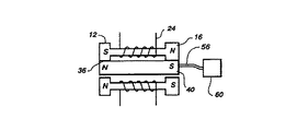
図1を参照して、本発明に従って製造される磁気偏心運動モータを示す。モータは4個の電磁石8a,8b,8c,8dから形成される固定子4を含んでいる。各電磁石はコアロッド20の両端に載置された強磁性材のエンドピース12,16を含んでいる。各コアロッド周りには電線24等の導電性コイルワイヤが巻回されている。各コアロッド周りに巻回されたコイルは整流子電流源28に接続され、それはコントロールユニット32からの信号に応答して、すぐに説明する所定の順序および所定の極性でコイルへ電流を供給する。すなわち、コントロールユニット32の制御の元で、電流源28はコイルへ一方向もしくは反対方向へ電流を供給したり、供給しなかったりする。
【0014】
電磁石8dのエンドピース12,16等のエンドピースは他のエンドピースと共に細長い一般的に円筒状の電機子40が転動できる弧状径路の一部を画定する、エンドピース12の表面領域36等の、内部弧状表面領域を有する円弧状に形成される。モータの電機子として作用する電機子40は図2に示すようなN極およびS極を有する永久磁石を構成する。明らかに、電機子40は公知の適切な材料により製造される。
【0015】
表面領域36等の電磁石のエンドピースの内部弧状表面領域は窒化シリコン等の耐摩耗材を被覆して電機子40とエンドピース表面間に生じる摩耗を防止することが有利である。
【0016】
図1に示すように、エンドピースの弧状内面により画定される径路内で電磁石8a,8b,8c,8dの各エンドピース間に配置された感知要素52に位置センサ回路44が導体48により接続されている。これらの感知要素は説明上位置センサ回路44から電流を受けそこを流れる電流が電機子40の位置および公知の印加電圧に応じて変化する電界効果型トランジスタデバイスとすることができる。このようにして、位置センサ回路44は固定子4内の電機子40の位置を決定することができる。
【0017】
位置センサ回路44は電機子40の位置を識別する信号をコントロールユニット32へ送り、次にコントロールユニット32は整流子電流源28へ信号を送って適切な電磁石へ電流を供給し選定された電磁石と永久磁石電機子40との間に磁気吸引および磁気反発を生じる。電磁石8a,8b,8c,8dを励起して電機子40を固定子内で転動させるシーケンス例のグラフを図3A〜図3Cに示す。各電磁石の一端だけを図3A〜図3Cに示し、それらの瞬時極性を(N極を表わす)“N”、(S極を表わす)“S”、および(中性すなわち無極性を表わす)“O”で示す。図3Aにおいて、N極端を示す電機子はS極を示す電磁石8bのエンドピースに対して配置されている。電磁石8bのエンドピースはN極性を示し、電磁石8cのエンドピースはS極性を示す。したがって、電機子40は電磁石8aのエンドピースにより反発され電磁石8b,8cのエンドピースにより吸引される。これにより、電機子40は固定子4内を反時計方向に移動させられる。図3Bにおいて、電磁石の3個のエンドピースは図示するように極性が変えられ電機子は電磁石8c,8dのエンドピースに向って吸引されるが電磁石8bのエンドピースに反発され、電機子は反時計方向の運動を継続する。最後に、図3Cにおいて、電磁石の3つのエンドピースは再び極性が変えられ電機子40は電磁石8cのエンドピースにより反発されかつ電磁石8d,8aのエンドピースにより吸引されて電機子40の反時計方向の転動が継続される。図3A〜図3Cとは反対端でモータから生じる磁力も同様に電機子40を図3A〜図3Cに示す方向に転動させる。
【0018】
電機子40は電磁石8a,8b,8c,8dのエンドピースの弧状内面と転動接触もしくは極めて接近するため、電機子と電磁石との間には極めて強力な磁力が生じる。また、電機子は固定子と転動接触していてベアリングに支持されないため電機子の移動による摩擦は少い。さらに、米国特許第4,922,164号に記載されているように、ギアリダクションは本質的に特殊なギアリングを要せずに達成される。
【0019】
図2を参照して、電機子40は可撓性連結機構すなわち軸56により電機子の回転により駆動される使用ユニット60へ連結されている。このようにして、図1および図2のモータのエネルギが利用される。さまざまな構造の連結機構が米国特許第4,922,164号で完全に検討されており、参照としてここに組み入れられている。
【0020】
説明上、コントロールユニット32はDEC VAX−LABもしくはIBM PC等の現在市販されているマイクロプロセッサもしくは他のプログラム内蔵コントロールユニットとすることができる。整流子電流源28はワイパー要素を含むモータ駆動ロータリスイッチとすることができ、ワイパー要素が回転させられる時に適切なシーケンスで適切な極性の電流源を選定されたワイヤコイル24へ接続する。また、整流子電流源28は適切なシーケンスおよび適切な極性で電磁石を励起することができる従来の電子整流子とすることができる。
【0021】
位置センサ44は各感知要素52および電流値、すなわち各感知要素が導通する電流の大きさ、を決定する電流検出器もしくは検出器バンクへ電流を供給し、次にどの感知要素52へ電機子40が最も近いかを識別するようにコントロールユニット32へ信号を与える信号回路へ電流を供給する電流源とすることができる。
【0022】
別の電機子位置感知構成は電磁石間の中央に配置された中空円筒状ケーシング内を転動するように電機子40が配置されかつケーシング内部が照明される光感知を含むことができる。ケーシング周りに円周方向に配置された開口を通る光を監視して電機子40の位置を決定することができる。明らかに、電機子が開口を一部覆う位置にある場合には、そこを光が通過せず従って電機子の位置が識別される。
【0023】
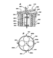
図4は一般的に円筒状の中空ケーシングすなわちハウジング104が設けられている本発明のもう一つの実施例の部分断面斜視図である。ケーシング104の両端にトラック108,112が形成されていて電機子124の各端に載置された各ディスク116,120はその上を転動することができる。一対のリッジ(係止部)すなわちリブ128,132をケーシング104の内面上に形成すれば、リッジの内径がディスク116,120の直径よりも小さいため電機子124の軸方向の移動を防止することができる。ケーシング104の内部には円周方向に間隔をとって複数個の電磁石136が配置されている。各電磁石136はエンドピース140,144(バー形状の)コア148および各コア148周りに巻回されたワイヤコイル152を含んでいる。
【0024】
図4の実施例における電機子124は図1および図2の実施例に示すような永久磁石とするか、もしくは単に磁気吸引材で作ることができる。電機子124が永久磁石であれば、図3A〜図3Cに関して説明した電機子の交互吸引および反発シーケンスを使用して電機子を駆動しディスク116,124をそれぞれトラック108,112上に転動させることができる。電機子124が磁気吸引材で出来ている場合には、電磁石136の電機子124吸引(反発ではない)を単に連続して励起および消勢して再びディスク116,120をトラック108,112上に転動させる。永久磁石電機子を設けることにより、電機子が単なる磁気吸引材で出来ている場合よりも大きい吸引力(および反発力)を発生することができる。
【0025】
図5、図6、図7および図8はすべて本発明のモータの電機子および固定子の設計に対するさまざまな別の構成の部分斜視端面図である。図5は星状断面を有する電機子が配置された一種の六角形空胴208を有する固定子204を示す。空胴208の側壁は電機子212と共に、電機子の回転時に電機子の点すなわちリブ216が内部空腔の側壁と継続的なスライド接触を維持するように形成される。図示するように、電機子の回転時にこのような継続的接触を行うように形成された固定子204と空胴208はジャイレータとして知られている。ここでも電機子212は永久磁石であり固定子204は複数の電磁石220で構成されている(図面を簡単にするために巻線、電流源等は図示されていないが、これらの構造は図1と同じとすることができる)。
【0026】
本発明の図5の構成はポンプとして利用することができ、電機子212のリブ216間のある位置で固定子204の内部へ流体を導入して電機子が回転すると流体は別の位置から排出される。例えば、電機子212が回転してリブ216aが開口に向って移動する時に開口224へ流体を導入することができる。次に、リブ216aが開口224から開口228へ向って回転すると、流体は固定子204の内部から排出される。
【0027】
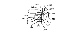
図6に方形断面を有する内部空胴238を画定する固定子234を示す。空胴238内には三角形断面を有する電機子242が配置されている。固定子234は空胴238周りに4個の電磁石246を含み電機子を交互に吸引および反発させて空胴内で増分回転(転動)させる。空胴238のコーナーには電機子が空胴238内を移動する時に接触する電機子位置センサ対250,254が配置されている。電機子242が各センサ対と接触すると、対応する導体258,262間の回路が閉成しこの状態を位置感知回路が感知してコントロールユニットへ情報を与え、前記したように整流子電流源から電磁石246への電流印加が制御される。
【0028】
図7に本発明のもう一つのモータ構成を示し、固定子304が五角形空胴306を画定し一般的に方形断面を有する電機子308がその内を転動するように配置されている。固定子304は空胴306周りに円周方向に配置され選択的に励起して電機子308を電機子308周りにステップ移動させる5個の電磁石312を含んでいる。図6の実施例について説明したように、電磁石312間に(図示せぬ)電機子位置センサを設けてセンサが電機子のコーナーと接触する時に回路を完了すなわち閉成することができる。
【0029】
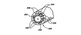
図8に示す本発明のモータの実施例では、固定子328により形成される内部空胴324の内壁に一連のスプライン332および溝336が形成され固定子内を縦方向に延在し側壁上で円周方向に間隔がとられている。電機子340が固定子空胴内に配置され電機子に沿って縦方向に延在しかつ円周方向に間隔のとられた歯車344を含み、歯の寸法は溝336に嵌合してスプライン332が歯間空間内に受容されるようにされている。前記したように、電磁石348が選択的に励起されると電機子340が固定子の空胴324内を転動する。
【0030】
図9に示す本発明のモータの実施例では、固定子354は一般的に互いに平行にかつ空胴362周りに円周方向に配置された複数の細長い永久磁石358により形成されている。拡張エンドピース358a,358bが電磁石358内に形成され互いに隣接配置されて内部弧状トラック366,370を画定する。空胴362内には強磁性材で出来た細長い円筒状電機子374がトラック366,370上を転動するように配置されている。ワイヤコイル378が空胴362周りにらせん状に巻回され、トラック366,370上を転動する時に電機子374と接触解除するようにされている。永久磁石358は異なる永久磁石の隣接エンドピース358a,358bが異極性を示すように配置されている。例えば、エンドピース358bは最頂部永久磁石がN極性を示し、固定子に対して時計廻りで、次の永久磁石がS極性を示し、再びS極性が続く。
【0031】
図9のモータは選択的に交番する極性の電流を供給して電機子374の極性を連続的に反転させ異なる永久磁石358に対して連続的に吸引および反発を行い電機子を空胴362内で転動させて作動する。図9の実施例では、電機子は最頂部永久磁石358へ向って吸引されるように示されている。電機子374の極性を切り替えると、電機子は時計方向で次の永久磁石へ向って吸引され、最頂部永久磁石により反発される。こうして、電機子374は前記したように空胴362内でトラック366,370上を転動する。
【0032】
図示はしないが、電機子374は図4に示す空胴ケーシング内に形成された特殊トラック上を転動する図4に示すようなディスクで形成することができる。もちろん、これにより永久磁石および電機子374間の摩耗を抑止することができる。
【0033】
極性切替え、すなわち一方から他方へ切替え次に一方へ戻す等、が必要なのは1個だけのワイヤコイル378であるため、図9のモータは簡単な整流子電流源を使用している。もちろん、本発明の他の実施例のように、多数の電磁石を使用するには、多数のコイルを必要とし各コイルを選択的に励起しなければならない。
【0034】
図10は複数の円筒方向に配置された電磁石416により形成された固定子の空胴408内に配置された中空円筒状電機子404を有する電磁偏心運動モータを示す。中空電機子404内に電機子404の内径よりも小さい直径を有する中実円筒状電機子420が配置されていて電機子420は電機子404内を転動することができる。電機子404,420は磁気吸引材で出来ており電磁石416を連続的に励起すると、電機子404,420により電機子404は固定子412の空胴408内を転動し、電機子420は電機子404の空胴内を転動する。両電機子404,420共同時に同じ電磁石に向って吸引されるが、電機子420よりも大径の電機子404は異なる角速度で転動してトルクおよび速度の異なる2つの動力源を提供する。
【0035】
電機子404は連結軸424を介して電機子404の回転従って軸424の回転により駆動される使用ユニット428へ連結される。軸424は電機子404へ直結するかもしくは電機子端を橋絡する(点線で示す)クロスピース432へ接続することができる。図10に示すように、電機子420は連結軸436を介して使用ユニット440へ連結される。
【0036】
図11Aおよび図11Bは本発明の電磁石を利用できる導体コイルの一実施例を示す。コイルは図11B(側断面図)に示すように、電磁石のコア508周りをらせん状に延在する導電材504の平坦な細片により構成されている。このようなコイル構造はコンパクトでしかもかなりの量の電流を運ぶことができる。コイル細片504はコイルの短絡を防止する絶縁被覆を含み、導電細片への電気的アクセスは単に角状切込み512を行い絶縁体から導電細片の一端を露呈させて行われる。
【0037】
図12、図13、図14はモータ電機子の偏心運動により生じる横力を減衰すなわち平衡させるモータ構成の部分斜視図である。図12はコーナーに4個の偏心運動モータ524が配置されている凾体520を示す。モータ524の電磁石を励起してその電機子を対角的に対向する各モータ対に対して対称的に反対方向へ移動させ、モータから生じる横力を有効に相殺する。例えば、モータ524の電機子は凾体520のコーナーに最も近い位置に示されており、この位置から電機子は凾体中心に最も近い位置へ移動され次に再びコーナーに最も近い位置へ戻って電機子により生じる横力を相殺することができる。
【0038】
図13に本発明に従って製造される偏心運動モータに生じる横力を減衰させる別の構成を示す。この実施例でも凾体540が設けられ、モータ544はスプリング548もしくは他の適切な緩衝要素により凾体548内に保持される。この構成では、モータ544の作動により生じる横力は平衡されずスプリング548により単に減衰される。簡単なコイルスプリングもしくは車輛に使用されるような精巧なショックアブソーバを使用することができる。
【0039】
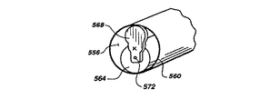
図14は本発明による平衡構成のもう一つの実施例の部分斜視図である。一般的に円筒状のケーシング560により囲まれた固定子の空胴556が示されている。(図示せぬ)電磁石がケーシング560周りに円周方向に配置されケーシング内に配置された円筒状電機子564を選択的に吸引および/もしくは反発させる。電機子564の各端に平衡体が載置され、その一つを符号568に示し、平衡体は電機子の回転軸572と一致する位置に枢着されている。したがって、平衡体は所望により軸572周りを旋回すなわち回転して電機子の所望の平衡を達成することができる。図示するように、平衡体568は回転軸572の軸から電機子564の横方向へ延在しケーシング560の電機子564と反対側の位置へ達する。平衡体はさまざまな形状とすることができるが、ケーシング560内にちょうど嵌合する弧状上端を有して電機子564の任意の移動により平衡体がケーシング内面を滑動しケーシングの電機子と反対側の位置を維持する方向に移動する。例えば、電機子564が反時計方向に転動すると、(ケーシング560の内面により平衡体はその方向とされるため)平衡体568も反時計方向に移動して電機子564および平衡体をケーシングの両側に維持する。こうして、平衡体の組合せ重量が電機子重量とほぼ同じとすると、電機子564の運動が平衡して横力は有効に相殺される。
【0040】
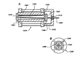
図15は円筒状電機子604の回転運動を2つの環状取付具608,612の並進運動へ変換するアクチュエータの部分断面斜視図である。電機子604はその両端にねじ616,620を含み、2組のねじは異なるサイズとされる。(図示せぬ)固定子が電機子604を囲んで配置され、それぞれ環状取付具608,612の内壁に形成されたねじ切りトラック624,628上を電機子604が転動するようにする。電機子604が転動すると、電機子のねじ616,620はそれぞれ環状取付具608,612のねじ624,628と噛み合い、環状取付具は電機子に対して縦方向に移動しそれは噛合ねじの方向および電機子の転動方向により決定される。
【0041】
環状取付具612は連結ロッド632を介してロッドを出し入れできる使用ユニット636へ連結されている。このようにして、電機子604の転動は環状取付具608,612の並進運動へ変換され、このような並進運動を使用して使用ユニット636へ動力を与えることができる。
【0042】
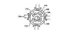
図16、図17、図18は本発明のモータに利用できる固定子構造の正面図である。各固定子構造は強磁性材の外部環状枠すなわち環704を含んでいる。円周方向に間隔をとった位置で環704から半径方向内向きに複数の支柱708が突出しており、図16および図17の構造の各支柱の内端には弧状表面領域716を画定する円弧部712が形成され、それは他の円弧部と共に一般的に円形の環の径路内部を画定する。図18の構造において、支柱708の内端には方形径路718を画定する直角コーナー部714が形成されている。一般的に円筒状の磁気吸引電機子720が前記したように吸引される時に図16および図17の弧状部712により形成される径路上を転動するように配置されている。図18において、三角形断面を有する電機子722が径路718周りをステップ状に“フロップ”するように配置されている。
【0043】
図16において電機子720を吸引および/もしくは反発させる磁力は環704上の各隣接支柱対708間の位置に導体巻線を設けて発生する。図16の実施例には4本の支柱708、したがって4個の巻線724がある。巻線724を選択的に励起することにより、弧状部712は電機子720を交互に吸引するような極性に磁化して弧状部により画定される径路内を転動させることができる。極性の例を図16に示し、“S”はS極を表わし“N”はN極を表わす。
【0044】
図17において、異なる巻線構成が提供され巻線724は支柱708周りに巻回されて弧状部716の磁極を選択的に変えることができる。
【0045】
図18の環704は図16と同様に巻回され、支柱708したがってコーナー部714の極性は連続的に変化して三角状電機子722は方形径路周りを連続的に“歩く”ことができる。
【0046】
次に図19Aおよび図19Bを参照して、可撓カップリング804の平面図および逆円錐状電機子808を使用した磁気偏心運動モータの側断面図をそれぞれ示す。すなわち、電機子808は一般的に平坦な頂面812および凹んだ円錐底面816を有する。電機子808は他の実施例の電機子について前記した強磁性材で出来ている。カップリング804はスプリング鋼等の可撓材で出来ており、材料の可撓性を高めるための複数の部分的円心状開口820を有するディスク状に形成されている。下面周辺において、電機子808の頂面812の周辺に形成された上向きに突出するリッジ824へカップリング804が取り付けられている。
【0047】
電機子808は、凹んだ円錐頂面830を有しかつ4個の電磁石832A,832B,832C,832Dが配置された円筒状凾体831を含む固定子828の頂面で旋回すなわち回転するように配置されている(図19A参照)。電磁石832は連続的に励起されて電機子808を連続的に吸引し固定子表面830上を円周方向に旋回および回転させる。各電磁石832はコア836を含み(図19B)その周りにコイル840が巻回されて周期的に電流を受けて電機子808を吸引する磁力を発生する。凾体831の底部にはコアおよびコイルを保持する鉄のエンドプレート844が配置されている。
【0048】
駆動軸848が固定子828内を回転するように配置されている。軸848の上端で軸周りにハブ852が載置され、それには図19Bに示すような可撓カップリング804が取り付けられている。軸848は固定子828の中心に配置された細長いベアリング856内に回転可能に収容される。固定子凾体831の底部で軸848を囲みかつエンドプレート844と接触して保持リング860が配置されている。
【0049】
電磁石832を連続的に励起すると、電機子808は電磁石へ連続的に吸引されて固定子828上を旋回かつ転動し可撓カップリング804を一緒に運ぶ。次に、可撓カップリング804がハブ852に連結されハブおよび軸848は電機子の回転と共に回転する。電機子808は可撓カップリング804により調整されるウォブル動作で旋回するが、軸848は固定子凾体内に保持されて固定軸周りを回転する。このようにして、旋回電機子808は可撓カップリング804を介して軸848を駆動する。
【0050】
図19Bのモータの整流は電機子の旋回径路内で固定子凾体831周りに円周方向に間隔をとった板ばね状の導電接触要素864と連続的に接触する電機子808により行われる。接触要素864が連続的に接触すると、電機子の旋回方向シーケンスの次の電磁石へ電流が供給され、電磁石は電機子の吸引力を発生し、後記するように電機子をその方向へ旋回させる。
【0051】
図20Aおよび図20Bは円錐状偏心運動モータの別の実施例であり固定子904にはやはり4個の電磁石908A,908B,908C,908Dが設けられている(図20B参照)。一般的に平坦な頂面916および凸状円錐底面920を有する電機子912が固定子凾体904の頂部の一般的に平坦な上板910上を旋回かつ転動するように配置されている。円筒状の中央アクスル924が電機子912の中心を一般的に直角に貫通している。円筒状アクスル924の下端は電機子912の下へ延在しかつ固定子凾体904の上板910に形成された開口928内へ延在している。曲った駆動軸932がアクスル924の中心を貫通し次にアクスルの下端で彎曲して固定子904の中心を下向きに延在している。駆動軸932はアクスル924内で回転可能であり、ベアリング936,940により回転可能に保持される。
【0052】
図19Aおよび図19Bの実施例と同様に、電磁石908を連続的に励起すると、電機子920がそこへ向って吸引され電機子は上板910上を円形運動を行って旋回および回転し、このような旋回により、駆動軸932は(電機子の旋回速度と同じ速度で)回転する。電機子920は強磁性材、上板910は真鍮やプラスチック等の非磁性材、アクスル924は真鍮もしくはプラスチック等の材料、駆動軸932は(ベアリングとして作用する)金属もしくは合金で作ることができる。
【0053】
4個のコンタクトクリップ944が固定子904の外部周りに円周方向に間隔をとって配置され、電機子920と接触するとそこから(図示せぬ電流源から)電流を受けて次の電磁石を連続的に励起し電機子を吸引して上板910上を旋回かつ転動させる。他のさまざまな整流構成については後記する。
【0054】
図21Aおよび図21Bはそれぞれ円錐状電機子1004を使用した磁気偏心運動モータのもう一つの実施例の側断面図および部分斜視図である。ここでも、電機子1004は一般的に平坦な上面1008および凸状円錐底面1012を含んでいるが、円錐面の頂点には枢動球受1016が形成されている。枢動球1020は固定子1028の頂壁1024の上面内に形成されている。電機子1004の円錐面1012の周辺には電機子を囲むリングギア1032が形成されている。リングギア1032は固定子1028の上部周辺周りに間隔をとって配置された4個の部分リングギアセグメント1036と噛合してその上を連続的に転動するように形成されている。後記するように、電機子が固定子上を旋回かつ回転する時に電機子1004の円錐底面1012と常時接触を維持するための導体リング1040も固定子の上壁1024上に配置されている。4個の電磁石1044は前記した円錐状電機子モータと同様に固定子1028内に配置されている。
【0055】
クランク状の駆動軸1048が下端で電機子1004の頂面1008へ枢着され、上端でベアリング1052,1056により一般的に垂直アライメント保持されている。
【0056】
動作について、電磁石1044は連続的に励起され電機子1004を吸引して枢動球1016上で枢動させ部分リングギア1036上を旋回かつ転動させる。すなわち、リングギア1032は対応する電磁石1044が励起されると部分リングギア1036と順次接触してその上を転動する。電機子1004が回転すると、駆動軸1048が回転して所望の駆動力が得られる。
【0057】
電磁石1044の整流は導体リング1040へ電流を供給し次に(導体リングと常時転動接触している)電機子1004を介してリングギア1032と接触する部分リングギア1036へ順次供給して行われる。次に、部分リングギア1036は各電磁石1044へ電流を供給して励起し電機子1004を回転させる。
【0058】
図22Aおよび図22Bはそれぞれ磁気偏心運動モータの平面図および側断面図である。ここでも、凾体1062内に4個の電磁石1060A,1060B,1060C,1060Dが設けられその頂部には円錐状回転子すなわち電機子1064が旋回するように配置されている。前記円錐状電機子の実施例と同様に、凾体1062の上部周辺上に形成された歯車1068と噛合する歯車1066が電機子1064の底部周辺に形成されている。下向きに突出する環1070が電機子1064の底面上に形成され凾体1062頂部に形成された空胴1072内に受容され旋回する。駆動軸1074は上端が電機子1064へ枢着されベアリング1076,1078により回転可能に保持される。駆動軸1074を円錐状電機子へ連結する2つの構成例を図23および図24に示す。
【0059】
図23に、駆動軸1082へ連結される円錐状電機子1080を示す。細長い空胴1084が電機子1080頂部に形成され中心部1084Aは電機子全体を貫通して駆動軸1082を受容する。クロスピース1086が駆動軸1082の横方向開口内に配置され空胴1084内に受容されていて、駆動軸がクロスピースの軸およびそれに直角な軸周りに旋回できるようにしながら中央部1084Aからスリップするのを防止する。空胴1084は電機子1080が固定子凾体上を旋回する時に駆動軸が固定子凾体内で実質的に一定の垂直位置にとどまることができるような方向に駆動軸1082が旋回運動を行うのに充分な大きさに形成される。
【0060】
図24は電機子1090と駆動軸1091間の、Uジョイント形式の、別の連結構成を示す。駆動軸1091は電機子1090の開口1092を通り直径方向に橋絡しかつ電機子を囲むリング1094に枢着されたクロスバー1093に固着されている。クロスバー1093はリング1094から直径方向両方向に延在するピン1095A,1095Bに枢着され駆動軸1091はリング1094に対して旋回することができる。次に、リング1094は電機子から直径方向両方向に延在するピン1096A,1096B上で電機子1090に枢着されている。リング1094を電機子1090に枢着することにより駆動軸1091はピン1095A,1095Bの直線軸により画定される軸だけでなくピン1096A,1096Bの直線軸により画定される軸周りを旋回することができる。したがって、前記したように電機子1090が固定子凾体の上面を旋回する間駆動軸1091を一般的に垂直に維持することができる。
【0061】
図25は本発明によるもう一つの円錐状電機子磁気モータの側断面図である。この実施例には、固定子1112の(歯車を有する)円錐状上面1108上を旋回かつ回転する双円錐状電機子1104(歯車を有する凹んだ円錐状頂面および底面)が設けられている。ここでも、電磁石1116を順次励起することにより電機子1104は固定子表面1108上を旋回かつ回転し、それにより電機子の円錐状上面は同時に円錐状ギア1120と接触してそれを回転させる。円錐状ギア1120の上面はベアリング1128により一定の回転可能位置に保持された駆動軸1124へ連結され、その下面はベアリング1136により回転可能に保持されたもう一つの駆動軸1132へ連結されている。ベアリング1128,1136および固定子は凾体1140内に収容されている。
【0062】
図26は(固定子1212のトラック1208上を偏心運動する)電機子1204を駆動軸1216へ連結するギア連結構成を示す。駆動軸1216は内面にリングギア1224が形成された連結リング1220へ連結されている。連結リング1220は固定子1212の凾体1232内に配置されたリングベアリング1228内を回転するように配置されている。電機子1204のトラック1208およびディスク1244上にそれぞれ噛合ギア1236,1240が形成されている。同様に、前方に突出するシリンダ1252周りにリングギア1248が形成されていてリングギア1224と噛合する。(図3には示していないが前述した電磁石により)電機子1204がトラック1208上を移動すると、電機子の突出シリンダ1252上のリングギア1248が連結リング1220のリングギア1224と噛合してそれを駆動し連結リングを回転させる。連結リング1220が回転すると、駆動軸1216は一定の“非軌道”で回転する。このようにして、図26の偏心運動モータはユニークなギア連結機構を介して駆動軸1216を駆動する。
【0063】
図27Aおよび図27Bは偏心回転電機子1304を駆動軸1308へ連結するもう一つの偏心運動モータ連結構成を示す。駆動軸1308は凾体1316内に配置されたベアリング1312により固定位置に回転可能に保持される。電機子1304は中空孔1320を有し、周辺のいくつかの点に取り付けられた可撓ディスク1328の中心に一端が固定されたロッド1324がその中を延在している。ロッド1324の他端は周辺のいくつかの点で駆動軸1308に取り付けられている可撓ディスク1332の中心に接合されている。ディスク1332およびリング1334は複数の円周方向に間隔のとられた剛性フィンガー1336により接合されている。可撓ディスク1328,1332は図19Aおよび図19Bの可撓カップリング804と同様な構成されている。電機子1304が固定子1340内で回転すると、ディスク1328が回転してロッド1324が回転する。ロッド1324が回転すると、ディスク1332が回転し、駆動軸1308に接続された連結リング1334が回転して駆動軸1308を所望により駆動する。ディスク1328,1332が可撓性であるため、ロッド1324は駆動軸1308に対して旋回かつ処理を行い電機子の回転力をロッドを介して駆動軸へ伝達する。
【0064】
図28はギア比を調整可能な偏心運動モータの側断面図である。前記したように、円錐台回転子1404が固定子1408内で偏心回転運動を行うように配置されている。回転子1404の一端はベアリング1416により滑動および回転可能に保持された可撓駆動軸1412に連結されている。
【0065】
駆動軸1412は(矢符1420で示す)縦方向に移動して固定子1408内の回転子1404の奥行を変えることにより、回転子の回転速度を変えることができる。すなわち、駆動軸1412が図28において右へ移動すると、回転子1404の回転速度が増大し、駆動軸1412が左へ移動すると回転子1404はさらに固定子1408内へ移動して回転速度が低下する。このようにして、単に駆動軸1412を縦方向に移動することによりギア比を調整することができる。
【0066】
図29は本発明の偏心運動モータの一つの整流構成を示す。この実施例では、その中を電機子1512の一端が転動する導電トラック1508に電流源1504が連結されている。トラック1508へ供給される電流は導電電機子1512へ流れ次に電機子1512の他端が転動するトラックセグメント1516へ順次流れる。トラックセグメント1516の一つへ供給された電流は各電磁石1520へ流れて電磁石へ電機子1512を吸引させトラック1508,1516内で転動させる。電機子1512が一つのトラックセグメント1516と接触を絶ってもう一つのトラックセグメントと接触すると、次の電磁石が励起されてその電磁石の方向へ電機子を吸引し電機子を継続的に転動させる。このようにして、電機子1512が転動すると電磁石1520の整流が自動的に行われる。
【0067】
図30は固定子の4個の導電セグメント1608内で回転子1604の双方向回転を行う整流構成を示す。電磁石1612が各セグメント1608に隣接配置されて回転子1604を順次吸引し固定子内で回転させる。電磁石1612は導電回転子1604へ電流を供給する電流源1616によりいずれかの方向へ順次励起され、次に現在回転子が接触しているいずれの固定子セグメント1608へも電流が供給される。この固定子セグメントから、回転子1604がそこへ向って転動する固定子セグメント1608に隣接する電磁石1612へ電流が流れる。例えば、回転子1604が反時計方向に転動し固定子セグメント1608aと接触しているものとする。この位置において、電流は回転子1604から固定子セグメント1608aおよびダイオード1620を介して電磁石1612bへ流れる。したがって、電磁石1612bが励起されて回転子1604を吸引しその反時計廻り運動を継続させる。回転子1604の時計方向の運動に対しては、単に電流源1616の極性を変えるだけである。
【0068】
電流源1616と回転子1604の連結は最初に電流源を回転子が転動する導電リングへ連結し連続時に接触を維持して行われる。また、固定子セグメントにより電流源を回転子と相互接続することもできる。
【0069】
前記構成は本発明の原理の応用を説明するものにすぎない。同業者ならば本発明の精神および範囲内でさまざまな修正や変更が可能と思われ、このような修正や変更は特許請求の範囲に含まれるものとする。
【図面の簡単な説明】
【図1】 本発明の原理に従って作られた電磁偏心運動モータの斜視図。
【図2】 図1のモータの側断面図。
【図3】 固定子の電磁石をさまざまに励起する場合に固定子内を転動する電機子の連続位置を示すグラフであって、Aでは電機子がS極を示す電機子のエンドピースに対向し、Bでは電機子が電磁石8c,8dのエンドピースに向って吸引され電磁石8bのエンドピースから反発されるようにされ、Cでは電機子が電磁石8cのエンドピースから反発され電磁石8d,8aのエンドピースにより吸引されることを示すグラフ。
【図4】 本発明の原理に従って製造された磁気偏心運動モータのもう一つの実施例の斜視および断面図。
【図5】 ポンプとして使用することができる本発明の偏心運動モータの一つの構成の部分斜視図。
【図6】 一般的に方形の断面を有する固定子と一般的に三角形の断面を有する電機子とを有する磁気偏心運動モータの部分斜視図。
【図7】 五角形断面の固定子と方形断面の電機子を有する磁気偏心運動モータの部分斜視図。
【図8】 それぞれギアトラックおよびギアティースを形成した固定子および電機子を有する磁気偏心運動モータの部分斜視図。
【図9】 電機子が電磁石として形成されている本発明の原理に従って製造された磁気偏心運動モータのもう一つの実施例の斜視および断面図。
【図10】 一方が他方の空胴内に配置されている2つの電機子を使用した磁気偏心運動モータのもう一つの実施例の部分斜視図。
【図11】 本発明の原理に従って製造された細分導体を巻回した電磁石のAは斜視図、Bは側断面図。
【図12】 モータの動作中に生じる横力を平衡させるための4個の固定子および4個の電機子を使用した磁気偏心運動モータの部分斜視図。
【図13】 制動要素がモータの固定子をモータ凾体へ接続してモータの動作により生じる横力を制動する磁気偏心運動モータの部分断面斜視図。
【図14】 モータの動作により生じる横力を平衡させるために電機子に取り付けられた平衡要素を含む磁気偏心運動モータの斜視断面図。
【図15】 回転運動を並進運動へ変換する磁気偏心運動モータの部分断面、斜視側面図。
【図16】 本発明の磁気偏心運動モータの固定子として使用するのに適した電磁石のもう一つの実施例の正面図。
【図17】 電磁石コイルが構造の異なる部分に巻回されている図16の電磁石の正面図。
【図18】 本質的に方形の回転子径路を有する図16および図17の電磁石と同様に構成された電磁石の正面図。
【図19】 Aは可撓性カップリングの平面図、Bは逆円錐状回転子を使用した磁気偏心運動モータの側断面図。
【図20】 円錐状回転子を使用した磁気偏心運動モータのもう一つの実施例のAは側断面図、Bは平面図。
【図21】 円錐状回転子磁気偏心運動モータのもう一つの実施例のAは側断面図、Bは部分平面斜視図。
【図22】 円錐状回転子磁気偏心運動モータの一つの実施例のAは平面図、Bは側断面図。
【図23】 偏心運動モータの円錐状回転子と回転子駆動軸間のカップリングの斜視図。
【図24】 偏心運動モータの円錐状回転子と回転子駆動軸間のカップリングのもう一つの実施例の斜視図。
【図25】 非ウォブル軸構成の円錐状磁気偏心運動モータのもう一つの実施例の側断面図。
【図26】 本発明の原理に従って製造された磁気偏心運動モータギアカップリングの側断面図。
【図27】 本発明の磁気偏心運動モータに使用する可撓性カップリング機構のAは側断面図、Bは端面図。
【図28】 可調整ギア比を有する磁気偏心運動モータの側断面図。
【図29】 整流構成の一実施例を有する磁気偏心運動モータの斜視側断面図。
【図30】 整流構成のもう一つの実施例を有する磁気偏心運動モータの平面図。
【符号の説明】
4 固定子
8a 電磁石
8b 電磁石
8c 電磁石
8d 電磁石
12 エンドピース
16 エンドピース
20 コアロッド
24 電線
28 整流子電流源
32 コントロールユニット
36 表面領域
40 電機子
44 位置センサ回路
48 導体
52 感知セグメント
56 軸
60 使用ユニット
104 ハウジング
108 トラック
112 トラック
116 ディスク
120 ディスク
124 電機子
128 リブ
132 リブ
136 電磁石
140 エンドピース
144 エンドピース
148 コア
152 ワイヤコイル
204 固定子
208 空胴
212 電機子
216 リブ
216a リブ
220 電磁石
224 開口
228 開口
234 固定子
238 空胴
242 電機子
246 電磁石
250 電機子位置センサ
254 電機子位置センサ
258 導体
260 導体
304 固定子
306 空胴
308 電機子
312 電磁石
324 空胴
328 固定子
332 スプライン
336 溝
340 電機子
344 歯車
348 電磁石
354 固定子
358 永久磁石
358a エンドピース
358b エンドピース
362 空胴
366 弧状トラック
370 弧状トラック
374 電機子
378 ワイヤコイル
404 電機子
408 空胴
412 電機子
416 電磁石
420 電機子
424 軸
428 使用ユニット
432 クロスピース
440 使用ユニット
504 コイル細片
508 コア
512 角状切込
520 凾体
524 偏心運動モータ
540 凾体
544 モータ
548 スプリング
556 空胴
560 ケーシング
564 電機子
568 平衡体
572 回転軸
604 電機子
608 環状取付具
612 環状取付具
616 ねじ
620 ねじ
624 トラック
628 トラック
632 連結ロッド
636 使用ユニット
704 環
708 支柱
712 円弧部
714 コーナー部
716 弧状表面領域
718 径路
720 電機子
722 電機子
724 巻線
804 可撓カップリング
808 逆円錐状電機子
812 頂面
816 底面
820 円心状開口
824 リッジ
828 固定子
830 円錐頂面
831 円筒状凾体
832 電磁石
832a 電磁石
832b 電磁石
832c 電磁石
836 コア
840 コイル
844 エンドプレート
848 駆動軸
852 ハブ
856 ベアリング
860 保持リング
864 導電接触要素
904 固定子
908a 電磁石
908b 電磁石
908c 電磁石
908d 電磁石
910 上板
912 電機子
916 平坦頂面
920 電機子
924 アクスル
928 開口
932 駆動軸
936 ベアリング
940 ベアリング
944 コンタクトクリップ
1004 円錐状電機子
1008 上面
1012 底面
1016 枢動球
1020 枢動球
1024 頂壁
1028 固定子
1032 リングギア
1036 リングギアセグメント
1040 導電リング
1044 電磁石
1048 駆動軸
1052 ベアリング
1056 ベアリング
1060A 電磁石
1060B 電磁石
1060C 電磁石
1060D 電磁石
1062 凾体
1064 電機子
1066 歯車
1068 歯車
1070 環
1072 空胴
1074 駆動軸
1076 ベアリング
1078 ベアリング
1080 電機子
1082 駆動軸
1084 空胴
1084A 中心部
1086 クロスピース
1090 電機子
1091 駆動軸
1092 開口
1093 クロスバー
1094 リング
1095A ピン
1095B ピン
1096A ピン
1096B ピン
1104 双円錐状電機子
1108 上面
1112 固定子
1116 電磁石
1120 円錐状ギア
1124 駆動軸
1128 ベアリング
1132 駆動軸
1136 ベアリング
1140 凾体
1204 電機子
1208 トラック
1212 固定子
1216 駆動軸
1220 連結リング
1224 リングギア
1228 リングベアリング
1232 凾体
1236 ギア
1240 ギア
1244 ディスク
1248 リングギア
1252 シリンダ
1304 偏心回転電機子
1308 駆動軸
1312 ベアリング
1316 凾体
1320 中空孔
1324 ロッド
1328 可撓ディスク
1332 可撓ディスク
1334 リング
1336 フィンガ
1404 円錐台回転子
1408 固定子
1412 可撓駆動軸
1416 ベアリング
1504 電流源
1508 トラック
1512 電機子
1516 トラックセグメント
1520 電磁石
1604 回転子
1608 導電セグメント
1068a 固定子セグメント
1612 電磁石
1612b 電磁石
1616 電流源
1620 ダイオード[0001]
[Industrial application fields]
The present invention relates to a magnetic starting eccentric motor having an armature that rolls in a stator.
[0002]
[Prior art]
An electric motor typically includes a stator and a rotatable armature, and electromagnetic force is generated between the two to rotate the armature. The armature is supported by a bearing to maintain a certain distance between the armature and the stator, and of course this causes friction. Moreover, the electromagnetic force becomes weaker as the distance between the armature and the stator is larger.
[0003]
Several proposals have been made for motors and actuators in which an armature or roller rolls inside a cylindrical cavity by electromagnetic force. The electromagnetic force is generated in a sequence along the periphery of the cavity and attracts the armature made of ferromagnetic material. See, for example, U.S. Pat. Nos. 2,561,890, 4,728,837 and 4,482,828, German DAS 1132229 and Swiss 159,716. The disadvantages of such prior art mechanisms are generally very large and heavy mechanisms that cannot be easily miniaturized and have a low energy density. This occurs because of the need for components that can generate sufficient electromagnetic force to properly operate the mechanism.
[0004]
Electrostatic motors are also generally stators and The armature is mounted so as to rotate near or within the stator, and the attractive force between them is not an electromagnetic force but an electrostatic force. Examples of electrostatic motors are shown in US Pat. Nos. 735,621, 3,297,888, 3,517,225 and 4,225,801. Recently published U.S. Pat. No. 4,922,164 discloses an eccentric electrostatic motor having a cylindrical armature arranged for rolling engagement with a hollow cylindrical stator. Elongated conductive strips are disposed on the inner wall of the stator cavity and are spaced circumferentially around the cavity. The conductive strip continuously receives the electric charge, attracts the armature, and rolls in the stator cavity.
[0005]
Generally, an electrostatic motor may be lighter and smaller in size than an electromagnetic motor, but generally has a weak attractive force.
[0006]
[Problems to be solved by the invention]
It is an object of the present invention to provide an electromagnetic motor that can be easily miniaturized without impairing the attractive force required for a desired operation.
[0007]
It is also an object of the present invention to provide a motor that can utilize both the magnetic attractive force and the magnetic repulsive force for the operation of the motor.
[0008]
It is also an object of the present invention to provide a motor that can minimize the frictional force between the stator and the armature.
[0009]
It is also an object of the present invention to provide a motor having high energy density with a high gear ratio.
[0010]
It is also an object of the present invention to provide a motor that is simple in design and easy to assemble and use.
[0011]
[Means for Solving the Problems]
The above and other objects of the present invention include a stator defining a closed continuous surface path, an armature consisting of a permanent magnet rollably mounted on the closed surface path, and disposed on a closed surface in the stator. Magnetic eccentric motor including a series of electromagnetic elements that are selectively excited to alternately attract and repel the armature to roll the armature along a closed surface path, and a circuit that selectively excites the electromagnetic element This is realized by the specific embodiment. A coupling mechanism can be used to couple the armature rotation to the device used, where the mechanical output of the motor can actually be used.
[0012]
In accordance with one aspect of the present invention, the electromagnetic element includes elongated electromagnets disposed at spaced locations along a path in the stator, the electromagnets generally being parallel to each other and having their poles aligned. Yes. The armature also includes an elongated, generally cylindrical bar whose poles are arranged to roll in a path adjacent to the matched poles of the electromagnet. The excitation circuit includes a commutator circuit that continuously supplies current to the electromagnet to alternately attract and repel the armature that rolls along the path.
[0013]
【Example】
Referring to FIG. 1, a magnetic eccentric motor manufactured in accordance with the present invention is shown. The motor includes a
[0014]
An end piece, such as
[0015]
The inner arcuate surface region of the electromagnet end piece, such as the
[0016]
As shown in FIG. 1, a position sensor circuit 44 is connected by a
[0017]
The position sensor circuit 44 sends a signal identifying the position of the
[0018]
Since the
[0019]
Referring to FIG. 2, the
[0020]
For illustrative purposes, the
[0021]
The position sensor 44 supplies current to a current detector or detector bank that determines each
[0022]
Another armature position sensing configuration can include light sensing where the
[0023]
FIG. 4 is a partial cross-sectional perspective view of another embodiment of the present invention in which a generally cylindrical hollow casing or
[0024]
The
[0025]
5, 6, 7 and 8 are all partial perspective end views of various alternative configurations for the armature and stator design of the motor of the present invention. FIG. 5 shows a kind of hexagon in which armatures having a star-shaped cross section are arranged.
[0026]
The configuration of FIG. 5 of the present invention can be used as a pump. When a fluid is introduced into the
[0027]
FIG. 6 shows a
[0028]
FIG. 7 shows another motor configuration of the present invention, in which a
[0029]
In the embodiment of the motor of the present invention shown in FIG. 8, a series of
[0030]
In the motor embodiment of the present invention shown in FIG. 9, the
[0031]
The motor of FIG. 9 selectively supplies alternating alternating currents to continuously reverse the polarity of the
[0032]
Although not shown, the
[0033]
The motor of FIG. 9 uses a simple commutator current source because only one
[0034]
FIG. 10 illustrates an electromagnetic eccentric motor having a hollow
[0035]
The
[0036]
FIG. 11A and FIG. 11B shows an embodiment of a conductor coil that can utilize the electromagnet of the present invention. As shown in FIG. 11B (side sectional view), the coil is composed of a flat strip of a
[0037]
FIGS. 12, 13, and 14 are partial perspective views of a motor configuration that attenuates or balances the lateral force generated by the eccentric motion of the motor armature. FIG. 12 shows a
[0038]
FIG. 13 shows another configuration for attenuating the lateral force generated in the eccentric motor manufactured according to the present invention. Again, a
[0039]
FIG. 14 is a partial perspective view of another embodiment of a balanced configuration according to the present invention. A
[0040]
FIG. 15 is a partial cross-sectional perspective view of an actuator that converts the rotational movement of the
[0041]
The annular fixture 612 is connected to a
[0042]
16, FIG. 17, and FIG. 18 are front views of a stator structure that can be used in the motor of the present invention. Each stator structure includes an outer annular frame or ring 704 of ferromagnetic material. A plurality of
[0043]
In FIG. 16, the magnetic force that attracts and / or repels the
[0044]
In FIG. 17, a different winding configuration is provided and the winding 724 can be wound around the
[0045]
The
[0046]
19A and 19B, a plan view of a
[0047]
The
[0048]
Drive
[0049]
When the electromagnet 832 is continuously excited, the
[0050]
The commutation of the motor of FIG. 19B is performed by an
[0051]
20A and 20B show another embodiment of the conical eccentric motor, and the
[0052]
As in the embodiment of FIGS. 19A and 19B, when the
[0053]
Four contact clips 944 are arranged around the outside of the
[0054]
21A and 21B are a side sectional view and a partial perspective view of another embodiment of a magnetic eccentric motor using a
[0055]
A crank-shaped
[0056]
In operation, the
[0057]
The rectification of the
[0058]
22A and 22B are a plan view and a side sectional view of the magnetic eccentric motor, respectively. Again, four
[0059]
FIG. 23 shows a
[0060]
FIG. 24 shows another connection configuration of the U joint type between the
[0061]
FIG. 25 is a side sectional view of another conical armature magnetic motor according to the present invention. This embodiment is provided with a biconical armature 1104 (recessed conical top and bottom surfaces with gears) that pivots and rotates on a conical upper surface 1108 (with gears) of the
[0062]
FIG. 26 shows a gear connection configuration for connecting the armature 1204 (moving eccentrically on the
[0063]
FIGS. 27A and 27B show another eccentric motor connection configuration for connecting the eccentric
[0064]
FIG. 28 is a cross-sectional side view of an eccentric motor with adjustable gear ratio. As described above, the
[0065]
The
[0066]
FIG. 29 shows one commutation configuration of the eccentric motor of the present invention. In this embodiment, a
[0067]
FIG. 30 shows a rectifying arrangement for bi-directional rotation of the
[0068]
The connection between the
[0069]
The above configuration is merely illustrative of the application of the principles of the present invention. Within the spirit and scope of the present invention Za Various modifications and changes are considered possible, and such modifications and changes are intended to be included in the scope of the claims.
[Brief description of the drawings]
FIG. 1 is a perspective view of an electromagnetic eccentric motor made in accordance with the principles of the present invention.
FIG. 2 is a side sectional view of the motor of FIG.
FIG. 3 is a graph showing a continuous position of an armature that rolls in the stator when the electromagnets of the stator are excited variously. In A, the armature faces the end piece of the armature showing the S pole. In B, the armature is attracted toward the end pieces of the
FIG. 4 is a perspective and cross-sectional view of another embodiment of a magnetic eccentric motor manufactured in accordance with the principles of the present invention.
FIG. 5 is a partial perspective view of one configuration of an eccentric motor of the present invention that can be used as a pump.
FIG. 6 is a partial perspective view of a magnetic eccentric motor having a stator having a generally square cross section and an armature having a generally triangular cross section.
FIG. 7 is a partial perspective view of a magnetic eccentric motor having a stator with a pentagonal cross section and an armature with a square cross section.
FIG. 8 is a partial perspective view of a magnetic eccentric motor having a stator and an armature that form gear tracks and gear teeth, respectively.
FIG. 9 is a perspective and cross-sectional view of another embodiment of a magnetic eccentric motor manufactured in accordance with the principles of the present invention in which the armature is formed as an electromagnet.
FIG. 10 is a partial perspective view of another embodiment of a magnetic eccentric motor using two armatures, one disposed within the other cavity.
11A is a perspective view and FIG. 11B is a side sectional view of an electromagnet wound with a fine conductor manufactured according to the principle of the present invention.
FIG. 12 is a partial perspective view of a magnetic eccentric motor using four stators and four armatures for balancing lateral forces generated during operation of the motor.
FIG. 13 is a partial cross-sectional perspective view of a magnetic eccentric motion motor in which a braking element connects a stator of a motor to a motor housing and brakes a lateral force generated by the operation of the motor.
FIG. 14 is a perspective cross-sectional view of a magnetic eccentric motor including a balancing element attached to the armature to balance the lateral force generated by the operation of the motor.
FIG. 15 is a partial cross-sectional, perspective side view of a magnetic eccentric motor that converts rotational motion into translational motion.
FIG. 16 is a front view of another embodiment of an electromagnet suitable for use as a stator of a magnetic eccentric motor of the present invention.
17 is a front view of the electromagnet shown in FIG. 16 in which an electromagnet coil is wound around different parts of the structure.
18 is a front view of an electromagnet configured similar to the electromagnet of FIGS. 16 and 17 having an essentially square rotor path. FIG.
FIG. 19A is a plan view of a flexible coupling, and B is a side sectional view of a magnetic eccentric motor using an inverted conical rotor.
20A is a side sectional view, and B is a plan view of another embodiment of a magnetic eccentric motor using a conical rotor. FIG.
21A is a side sectional view and FIG. 21B is a partial plan perspective view of another embodiment of a conical rotor magnetic eccentric motor.
22A is a plan view and FIG. 22B is a side sectional view of one embodiment of a conical rotor magnetic eccentric motor.
FIG. 23 is a perspective view of a coupling between a conical rotor and a rotor drive shaft of an eccentric motor.
FIG. 24 is a perspective view of another embodiment of the coupling between the conical rotor and the rotor drive shaft of the eccentric motor.
FIG. 25 is a side sectional view of another embodiment of a conical magnetic eccentric motor with a non-wobble shaft configuration.
FIG. 26 is a cross-sectional side view of a magnetic eccentric motor gear coupling manufactured in accordance with the principles of the present invention.
27A is a side sectional view and B is an end view of a flexible coupling mechanism used in the magnetic eccentric motor of the present invention. FIG.
FIG. 28 is a sectional side view of a magnetic eccentric motor having an adjustable gear ratio.
FIG. 29 is a perspective side sectional view of a magnetic eccentric motor having one embodiment of a rectifying configuration.
FIG. 30 is a plan view of a magnetic eccentric motor having another embodiment of a rectifying configuration.
[Explanation of symbols]
4 Stator
8a electromagnet
8b electromagnet
8c electromagnet
8d electromagnet
12 Endpiece
16 End piece
20 core rod
24 electric wire
28 Commutator current source
32 Control unit
36 Surface area
40 Armature
44 Position sensor circuit
48 conductors
52 sensing segments
56 axes
60 units used
104 Housing
108 tracks
112 tracks
116 discs
120 disks
124 Armature
128 ribs
132 Ribs
136 Electromagnet
140 Endpiece
144 End piece
148 core
152 wire coil
204 Stator
208 Cavity
212 Armature
216 ribs
216a rib
220 electromagnet
224 opening
228 opening
234 Stator
238 Cavity
242 Armature
246 Electromagnet
250 Armature position sensor
254 Armature position sensor
258 conductor
260 conductors
304 Stator
306 Cavity
308 Armature
312 electromagnet
324 Cavity
328 Stator
332 spline
336 groove
340 Armature
344 gear
348 Electromagnet
354 stator
358 Permanent magnet
358a End piece
358b end piece
362 Cavity
366 arc track
370 arc track
374 Armature
378 wire coil
404 Armature
408 Cavity
412 Armature
416 electromagnet
420 Armature
424 axes
428 Units used
432 Crosspiece
440 units used
504 Coil strip
508 core
512 square cut
520 body
524 Eccentric motor
540 body
544 motor
548 Spring
556 Cavity
560 casing
564 Armature
568 equilibrium
572 axis of rotation
604 Armature
608 Annular fitting
612 Ring fitting
616 screw
620 screw
624 tracks
628 tracks
632 Connecting rod
636 units used
704 ring
708 prop
712 Arc part
714 Corner
716 Arc surface area
718 path
720 Armature
722 Armature
724 winding
804 Flexible coupling
808 Inverted conical armature
812 Top surface
816 Bottom
820 circular opening
824 Ridge
828 stator
830 Conical top surface
831 Cylindrical housing
832 electromagnet
832a electromagnet
832b electromagnet
832c electromagnet
836 core
840 coil
844 End plate
848 Drive shaft
852 hub
856 Bearing
860 retaining ring
864 conductive contact elements
904 Stator
908a electromagnet
908b electromagnet
908c electromagnet
908d electromagnet
910 Upper plate
912 Armature
916 Flat top surface
920 Armature
924 Axle
928 opening
932 Drive shaft
936 Bearing
940 Bearing
944 Contact clip
1004 Conical armature
1008 Top surface
1012 Bottom
1016 Pivoting ball
1020 Pivoting ball
1024 top wall
1028 Stator
1032 ring gear
1036 Ring gear segment
1040 Conductive ring
1044 electromagnet
1048 Drive shaft
1052 Bearing
1056 Bearing
1060A electromagnet
1060B electromagnet
1060C electromagnet
1060D electromagnet
1062
1064 armature
1066 gear
1068 gear
1070 ring
1072 Cavity
1074 Drive shaft
1076 Bearing
1078 Bearing
1080 Armature
1082 Drive shaft
1084 cavity
1084A center
1086 crosspiece
1090 Armature
1091 Drive shaft
1092 opening
1093 crossbar
1094 ring
1095A pin
1095B pin
1096A pin
1096B pin
1104 Bicone armature
1108 Top surface
1112 Stator
1116 Electromagnet
1120 Conical gear
1124 Drive shaft
1128 Bearing
1132 Drive shaft
1136 Bearing
1140 housing
1204 Armature
1208 tracks
1212 Stator
1216 Drive shaft
1220 Connecting ring
1224 ring gear
1228 Ring bearing
1232 body
1236 Gear
1240 Gear
1244 disc
1248 Ring gear
1252 cylinder
1304 Eccentric rotating armature
1308 Drive shaft
1312 Bearing
1316 enclosure
1320 Hollow hole
1324 Rod
1328 Flexible disk
1332 Flexible disk
1334 ring
1336 Finger
1404 frustoconical rotor
1408 Stator
1412 Flexible drive shaft
1416 Bearing
1504 current source
1508 tracks
1512 Armature
1516 track segment
1520 electromagnet
1604 rotor
1608 Conductive segment
1068a Stator segment
1612 electromagnet
1612b electromagnet
1616 current source
1620 diode
Claims (7)
前記閉じた径路を形成する前記複数個の電磁石の内側表面に配置された、前記閉じた径路と関連した広がりをもって延在する一対のトラックと一対のリッジを画定する手段と、
一方の磁極が吸引されおよび/または反発されるときに閉じた径路を対面して転動するように配置されている永久磁石であって、バーと前記一対のトラックの各々の内で転動するように配置された一対のディスクとを備え、該永久磁石が前記閉じた径路に対面して転動するように前記一対のリッジを前記ディスクに作用させることによって前記バーの軸方向に移動しないようにした前記永久磁石と、
電磁石を選択的に励起して永久磁石を吸引しおよび/または反発させる励起手段であって、前記電磁石の一方の磁極が交番的に前記永久磁石を吸引しおよび反発して該永久磁石を前記径路に沿って転動させるように前記電磁石を励起する手段を有する前記励起手段と、
を備えた偏心運動モータ。A plurality of electromagnets arranged in an array around a closed space, wherein one of the magnetic poles of each electromagnet is arranged in series with the other, and the one of the magnetic poles defines a closed path; ,
Means for defining a pair of tracks and a pair of ridges disposed on an inner surface of the plurality of electromagnets forming the closed path and extending with an extent associated with the closed path;
A permanent magnet arranged to roll across a closed path when one magnetic pole is attracted and / or repelled, and rolls within each of the bar and the pair of tracks The pair of ridges act on the disk so that the permanent magnet rolls facing the closed path so that the permanent magnet does not move in the axial direction of the bar. Said permanent magnet,
Excitation means for selectively exciting an electromagnet to attract and / or repel a permanent magnet, wherein one magnetic pole of the electromagnet alternately attracts and repels the permanent magnet The excitation means having means for exciting the electromagnet to roll along
Eccentric motor with
該固定子の前記閉じた表面径路に対面して転動可能に配置された永久磁石を備えると共に、前記固定子の前記径路内で転動するように配置された磁極を有する前記円筒状バーを備えた電機子であって、該電機子が電磁石によって吸引されおよび/または反発されながら前記トラック上に接して転動するように前記円筒状バーまたはその各端部上に取り付けられた一対のディスクを備え、前記ディスクを前記リッジに作用させることによって前記電機子が軸方向に移動しないようにした前記電機子と、
前記閉じた表面において前記固定子に配置され、前記電機子を吸引しおよび/または反発するように継続的に励起可能にして該電機子を前記閉じた表面径路に対面し転動させる電磁要素であって、前記径路に沿って、相互に平行に間隔を置いて前記固定子に配置して磁極が整列するようにされた継続的に電流を受ける電磁石を備えた前記電磁要素と、
該電磁要素を継続的に励起する手段であって、前記電磁石に電流を継続的に供給するための整流子手段を有する前記手段と、
前記電機子を利用機構に結合する手段と、
を備えた利用機構駆動用偏心運動モータ。A stator that includes a pair of tracks that define a closed continuous surface path and that are spaced apart to surround each of the ends of an elongated generally cylindrical bar, said tracks being said fixed The stator having a ridge formed on the inner surface of the child; and
A cylindrical bar having a permanent magnet arranged to roll against the closed surface path of the stator and having a magnetic pole arranged to roll in the path of the stator; A pair of discs mounted on the cylindrical bar or each end thereof so that the armature rolls in contact with the track while being attracted and / or repelled by an electromagnet The armature that prevents the armature from moving in the axial direction by causing the disk to act on the ridge;
An electromagnetic element disposed on the stator at the closed surface and capable of continuously exciting the armature so as to attract and / or repel the armature against the closed surface path and roll The electromagnetic element comprising a continuous current receiving electromagnet arranged along the path and spaced apart in parallel to the stator to align the magnetic poles;
Means for continuously exciting the electromagnetic element, the means having commutator means for continuously supplying current to the electromagnet;
Means for coupling the armature to a utilization mechanism;
Eccentric motor for use mechanism drive equipped with
前記第1、第2、第3および第4の電機子を利用機構に結合する手段と、
を備え、
前記各永久磁石を交互に吸引しおよび/または反発するように継続的に励起可能にしてそれぞれ対角線方向に対向した対の前記各永久磁石を相互に対称的に反対方向に前記各閉じた表面径路に沿って転動させることによって前記各永久磁石の移動により生ずる横方向の力を相殺する、利用機構駆動用偏心運動モータ。Eccentric motors according to claims 1, 2, 3, and 4, which are arranged at corners of a virtual square,
Means for coupling the first, second, third and fourth armatures to a utilization mechanism;
With
Each said permanent magnet can be continuously excited so as to be attracted and / or repelled alternately, so that each pair of said permanent magnets facing each other in a diagonal direction is symmetrically opposite to each other and said each closed surface path An eccentric motion motor for driving the utilization mechanism that cancels lateral force generated by the movement of each permanent magnet by rolling along the axis.
前記固定子空胴の回りにアレー状に配置した複数個の電磁要素と、
前記固定子空胴内に配置され、強磁性材料の細長いバーと該バー上の間隔を置いた位置に取り付けられた一対のディスクとを有し、前記固定子の各トラック上を接触して転動するようにすると共に前記一対のリッジによって中心軸に沿って移動しないようにされた電機子と、
前記電磁要素を選択的に励起して前記電機子を継続的に吸引し、該電機子を前記固定子空胴の回りで前記トラック上を転動させるようにした励起手段と、
を備えた、偏心運動モータ。A stator defining a pair of closed, continuous surface tracks spaced generally around the stator cavity and arranged in parallel and forming a pair of ridges on the inner surface of the stator cavity;
A plurality of electromagnetic elements arranged in an array around the stator cavity;
It has an elongated bar of ferromagnetic material and a pair of discs mounted at spaced positions on the bar and is placed in the stator cavity, and contacts and rolls on each track of the stator. An armature configured to move and not to move along the central axis by the pair of ridges;
Excitation means for selectively exciting the electromagnetic element to continuously attract the armature and rolling the armature around the stator cavity on the track;
Equipped with an eccentric motor.
Priority Applications (1)
| Application Number | Priority Date | Filing Date | Title |
|---|---|---|---|
| JP09454392A JP3672326B2 (en) | 1992-04-14 | 1992-04-14 | Eccentric motor and fluid pump |
Applications Claiming Priority (1)
| Application Number | Priority Date | Filing Date | Title |
|---|---|---|---|
| JP09454392A JP3672326B2 (en) | 1992-04-14 | 1992-04-14 | Eccentric motor and fluid pump |
Related Child Applications (1)
| Application Number | Title | Priority Date | Filing Date |
|---|---|---|---|
| JP2003195791A Division JP2004007990A (en) | 2003-07-11 | 2003-07-11 | Eccentrically operating motor and fluid pump |
Publications (2)
| Publication Number | Publication Date |
|---|---|
| JPH06141527A JPH06141527A (en) | 1994-05-20 |
| JP3672326B2 true JP3672326B2 (en) | 2005-07-20 |
Family
ID=14113234
Family Applications (1)
| Application Number | Title | Priority Date | Filing Date |
|---|---|---|---|
| JP09454392A Expired - Fee Related JP3672326B2 (en) | 1992-04-14 | 1992-04-14 | Eccentric motor and fluid pump |
Country Status (1)
| Country | Link |
|---|---|
| JP (1) | JP3672326B2 (en) |
Families Citing this family (4)
| Publication number | Priority date | Publication date | Assignee | Title |
|---|---|---|---|---|
| US9093874B2 (en) | 2004-10-25 | 2015-07-28 | Novatorque, Inc. | Sculpted field pole members and methods of forming the same for electrodynamic machines |
| FR2934433B1 (en) * | 2008-07-22 | 2014-11-14 | Delachaux Sa | ECCENTRIC ROTOR ENGINE |
| JP4896103B2 (en) * | 2008-09-18 | 2012-03-14 | ジヤトコ株式会社 | Oil pump drive structure |
| US9124150B2 (en) * | 2013-07-12 | 2015-09-01 | The Boeing Company | Active-active redundant motor gear system |
-
1992
- 1992-04-14 JP JP09454392A patent/JP3672326B2/en not_active Expired - Fee Related
Also Published As
| Publication number | Publication date |
|---|---|
| JPH06141527A (en) | 1994-05-20 |
Similar Documents
| Publication | Publication Date | Title |
|---|---|---|
| US5606209A (en) | Magnetic eccentric motion motor | |
| JP4767488B2 (en) | Magnetic levitation pump | |
| CN102106063B (en) | There is the motor of eccentric rotor | |
| US7982353B2 (en) | Directed flux motor | |
| JP4539716B2 (en) | Actuator and electric electronic toothbrush using the same | |
| JPS62171458A (en) | Magnetic force rotating apparatus | |
| EA013829B1 (en) | Electric motor generator | |
| JP4504853B2 (en) | Motor structure | |
| JP2006217792A (en) | Induction motor having function to prevent reverse rotation | |
| US6897595B1 (en) | Axial flux motor with active flux shaping | |
| US20040251767A1 (en) | Axial flux electromotive generator having rotor magnets and shaped core assembly | |
| JP3672326B2 (en) | Eccentric motor and fluid pump | |
| JP3691834B2 (en) | Eccentric motor and fluid pump | |
| US5675197A (en) | Magnetic eccentric motion motor | |
| JP2021524218A (en) | Directionally balanced electric motor with air-core stator coil | |
| JP2004007990A (en) | Eccentrically operating motor and fluid pump | |
| CA2064529C (en) | Magnetic eccentric motion motor | |
| JP4685227B2 (en) | Magnetic levitation pump | |
| JP2004048873A5 (en) | ||
| JPH1042518A (en) | Motor driver | |
| JP3757733B2 (en) | Revolving actuator | |
| KR20030084210A (en) | Bearingless linear motor | |
| KR101029610B1 (en) | motor | |
| JP3650606B2 (en) | Electromagnetic clutch | |
| CA2009904C (en) | Eccentric motion motor |
Legal Events
| Date | Code | Title | Description |
|---|---|---|---|
| A601 | Written request for extension of time |
Free format text: JAPANESE INTERMEDIATE CODE: A601 Effective date: 20040114 |
|
| A602 | Written permission of extension of time |
Free format text: JAPANESE INTERMEDIATE CODE: A602 Effective date: 20040119 |
|
| A521 | Written amendment |
Free format text: JAPANESE INTERMEDIATE CODE: A523 Effective date: 20040414 |
|
| A131 | Notification of reasons for refusal |
Free format text: JAPANESE INTERMEDIATE CODE: A131 Effective date: 20040723 |
|
| A601 | Written request for extension of time |
Free format text: JAPANESE INTERMEDIATE CODE: A601 Effective date: 20041025 |
|
| A602 | Written permission of extension of time |
Free format text: JAPANESE INTERMEDIATE CODE: A602 Effective date: 20041101 |
|
| A521 | Written amendment |
Free format text: JAPANESE INTERMEDIATE CODE: A523 Effective date: 20050124 |
|
| TRDD | Decision of grant or rejection written | ||
| A01 | Written decision to grant a patent or to grant a registration (utility model) |
Free format text: JAPANESE INTERMEDIATE CODE: A01 Effective date: 20050318 |
|
| A61 | First payment of annual fees (during grant procedure) |
Free format text: JAPANESE INTERMEDIATE CODE: A61 Effective date: 20050419 |
|
| R150 | Certificate of patent or registration of utility model |
Free format text: JAPANESE INTERMEDIATE CODE: R150 |
|
| FPAY | Renewal fee payment (event date is renewal date of database) |
Free format text: PAYMENT UNTIL: 20090428 Year of fee payment: 4 |
|
| FPAY | Renewal fee payment (event date is renewal date of database) |
Free format text: PAYMENT UNTIL: 20100428 Year of fee payment: 5 |
|
| LAPS | Cancellation because of no payment of annual fees |