JP3671981B2 - Turbine shroud segment with bent cooling channel - Google Patents
Turbine shroud segment with bent cooling channel Download PDFInfo
- Publication number
- JP3671981B2 JP3671981B2 JP52574495A JP52574495A JP3671981B2 JP 3671981 B2 JP3671981 B2 JP 3671981B2 JP 52574495 A JP52574495 A JP 52574495A JP 52574495 A JP52574495 A JP 52574495A JP 3671981 B2 JP3671981 B2 JP 3671981B2
- Authority
- JP
- Japan
- Prior art keywords
- channel
- shroud segment
- lateral
- channels
- flow path
- Prior art date
- Legal status (The legal status is an assumption and is not a legal conclusion. Google has not performed a legal analysis and makes no representation as to the accuracy of the status listed.)
- Expired - Fee Related
Links
- 238000001816 cooling Methods 0.000 title description 25
- 239000012809 cooling fluid Substances 0.000 claims description 32
- 238000004891 communication Methods 0.000 claims description 4
- 239000012530 fluid Substances 0.000 description 25
- 239000007789 gas Substances 0.000 description 21
- 239000000758 substrate Substances 0.000 description 11
- 239000010408 film Substances 0.000 description 9
- 238000005266 casting Methods 0.000 description 5
- 238000000034 method Methods 0.000 description 5
- 238000012546 transfer Methods 0.000 description 4
- 239000011247 coating layer Substances 0.000 description 3
- 230000000694 effects Effects 0.000 description 3
- 238000007796 conventional method Methods 0.000 description 2
- 230000008569 process Effects 0.000 description 2
- 238000005086 pumping Methods 0.000 description 2
- 238000010926 purge Methods 0.000 description 2
- 238000011144 upstream manufacturing Methods 0.000 description 2
- 238000009825 accumulation Methods 0.000 description 1
- 238000007792 addition Methods 0.000 description 1
- 230000000712 assembly Effects 0.000 description 1
- 238000000429 assembly Methods 0.000 description 1
- 238000005452 bending Methods 0.000 description 1
- 238000007664 blowing Methods 0.000 description 1
- 239000011248 coating agent Substances 0.000 description 1
- 238000000576 coating method Methods 0.000 description 1
- 238000002485 combustion reaction Methods 0.000 description 1
- 238000009760 electrical discharge machining Methods 0.000 description 1
- 239000000446 fuel Substances 0.000 description 1
- 238000004519 manufacturing process Methods 0.000 description 1
- 230000007246 mechanism Effects 0.000 description 1
- 238000012986 modification Methods 0.000 description 1
- 230000004048 modification Effects 0.000 description 1
- 230000001172 regenerating effect Effects 0.000 description 1
- 238000007789 sealing Methods 0.000 description 1
- 239000012720 thermal barrier coating Substances 0.000 description 1
- 239000010409 thin film Substances 0.000 description 1
Images

Classifications
-
- F—MECHANICAL ENGINEERING; LIGHTING; HEATING; WEAPONS; BLASTING
- F01—MACHINES OR ENGINES IN GENERAL; ENGINE PLANTS IN GENERAL; STEAM ENGINES
- F01D—NON-POSITIVE DISPLACEMENT MACHINES OR ENGINES, e.g. STEAM TURBINES
- F01D11/00—Preventing or minimising internal leakage of working-fluid, e.g. between stages
- F01D11/08—Preventing or minimising internal leakage of working-fluid, e.g. between stages for sealing space between rotor blade tips and stator
-
- F—MECHANICAL ENGINEERING; LIGHTING; HEATING; WEAPONS; BLASTING
- F01—MACHINES OR ENGINES IN GENERAL; ENGINE PLANTS IN GENERAL; STEAM ENGINES
- F01D—NON-POSITIVE DISPLACEMENT MACHINES OR ENGINES, e.g. STEAM TURBINES
- F01D25/00—Component parts, details, or accessories, not provided for in, or of interest apart from, other groups
- F01D25/08—Cooling; Heating; Heat-insulation
- F01D25/12—Cooling
-
- Y—GENERAL TAGGING OF NEW TECHNOLOGICAL DEVELOPMENTS; GENERAL TAGGING OF CROSS-SECTIONAL TECHNOLOGIES SPANNING OVER SEVERAL SECTIONS OF THE IPC; TECHNICAL SUBJECTS COVERED BY FORMER USPC CROSS-REFERENCE ART COLLECTIONS [XRACs] AND DIGESTS
- Y02—TECHNOLOGIES OR APPLICATIONS FOR MITIGATION OR ADAPTATION AGAINST CLIMATE CHANGE
- Y02T—CLIMATE CHANGE MITIGATION TECHNOLOGIES RELATED TO TRANSPORTATION
- Y02T50/00—Aeronautics or air transport
- Y02T50/60—Efficient propulsion technologies, e.g. for aircraft
Landscapes
- Engineering & Computer Science (AREA)
- Mechanical Engineering (AREA)
- General Engineering & Computer Science (AREA)
- Turbine Rotor Nozzle Sealing (AREA)
Description
産業上の利用分野
本発明はガスタービンエンジンに関する。特に、そのようなエンジンのタービンシュラウドセグメントに関する。
背景技術
軸流ガスタービンエンジンは、長手方向軸に沿って順に配置されたコンプレッサ、燃焼器、及びタービンを含んでおり、環状の流路がこれらのコンプレッサ、燃焼器、タービンを通って軸方向に延在している。コンプレッサには動翼(rotating blade)が備わっており、流入する作動流体と相互作用してそれを圧縮する。圧縮された作動流体の一部は燃焼器内に入り、燃料と混合され点火される。燃焼生成物または高温ガスは、タービンを通って流れる。タービンにはベーン(vane)と動翼が交互に配置されており、高温ガスのエネルギーは動翼へと移動する。このエネルギーの一部は、回転シャフトを介してコンプレッサ部へと戻される。
タービンを流れる高温ガスと動翼とができるだけ効率よく相互作用するように、高温ガスは、内側及び外側タービンシュラウドによって画定された環状空間内を流れる。内側タービンシュラウドは、通常、動翼と一体に形成された複数のプラットフォームからなる。これらのプラットフォームは、隣接する動翼のプラットフォームと整合して内側流路面(inner flow surface)を形成している。外側シュラウドは、通常、動翼の外側先端部に近接してそれらの径方向外側に配置されたリング状アセンブリである。外側シュラウドは複数のアーチ型セグメントを含んでおり、これらのセグメントが周方向に隔置されて外側流路面(outer flow surface)を形成している。
シュラウドセグメントは高温ガスと直接接触するため、これらのシュラウドセグメントを許容される温度範囲内に保つためにはなんらかの冷却が必要である。冷却方法の中には、冷却流体をシュラウドセグメントの径方向外側面または裏面に当てる衝当冷却(impingement cooling)や、シュラウドセグメントに冷却孔を設けシュラウドセグメントの流路面全体に渡って冷却流体の薄膜を形成するフィルム式冷却(film cooling)がある。
衝当冷却及びフィルム式冷却のどちらもほとんどの状況で充分であったが、ガスタービンエンジンの進歩によりタービンを流れるガスは一層高温化してきており、この作動流体の高温化により、より効率のよい改善された冷却方法が必要となってきている。最近開示されたそのような方法の一つに、1994年12月27日に付与された米国特許第5,375,973号(タイトル“Turbine Blade Outer Air Seal With Optimized Cooling and Method of Fabrication”)に開示されたものがある。それによると、逆流アレイ(counter flow array)構造でシュラウドセグメントを貫通して横方向に延在する冷却チャネルが開示されている。これらのチャネルは、シュラウドセグメントの裏面に設けられた入口と、セグメント間ギャップへと冷却流体を放出する出口を含んでいる。また、チャネル内を流れる流体のマッハ数を制御するため、流れ方向に先細となった部分を含んでいる。
上記した構成では、シュラウドセグメントのリーディングエッジ(前縁)領域及びトレーリングエッジ(後縁)領域に冷却流体を供給する能力に限界がある。各シュラウドセグメントは、自身をステータ構造内の所定の位置に保持するため、リーディングエッジ領域及びトレーリングエッジ領域に隣接した保持手段を有している。通常、これらの保持手段は、シュラウドセグメントの裏面から径方向外向きに延出してエッジに沿って横方向に延在するレールまたはフックである。これらのフック及びレールは、冷却流体がこの領域へと流れてエッジ近辺の裏面に当たるのを妨げる。冷却流体の一部をこれらの領域へと導くようにフィルム冷却用流路に角度をつけることはできるが、完全な被覆が達成されるようにフィルム冷却用流路を十分に浅い角度で形成することは実際的ではない。結局、これらのフック及びレールはそれらの下の横方向チャネル(lateral channel)内に冷却流体が直接流入するのを阻止し、裏面からフック及びレールの下までリーディングエッジ及びトレーリングエッジ領域全体に延在するキャビティが必要となる。そうすると、フック及びレールはシュラウドセグメントから一層外向きに延び、シュラウドセグメントの重さ及び剛直性を増す結果となる。
独立請求項である請求項1の前提部分(precharacterizing portion)に規定されたガスタービンエンジン用シュラウドセグメントは、FR-A-2 359 976に開示されている。FR-A-2 359 976のシュラウドセグメントは、トレーリングエッジに沿って形成された曲折したチャネルを有している。入口ダクトは曲折チャネルの外側流路に接続されており、曲折チャネルの内側流路は、シュラウドセグメントの内向き流路面に設けられた出口オリフィス手段に接続されている。
上述した技術はあるが、本出願人の指導の下で働いている研究者及び技術者によって、ガスタービンエンジン用の効率よく冷却可能なタービンシュラウドセグメントが開発された。
発明の開示
本発明に基づくタービンシュラウドセグメントは、独立請求項によって画定されているように、軸側エッジ(axial edge)の少なくとも一つに沿って延在する曲折したチャネルを含む。この曲折チャネルは、内側流路、外側流路、及びダクトを含む。外側流路がエッジの最も近くに位置し、外側流路と内側流路は連通している。ダクトは、曲折流路内に冷却空気が流入して流れることができるように、シュラウドセグメントの裏面に形成された開口から内側流路へと延在している。
曲折チャネルのこのような特徴によって、シュラウドセグメントのエッジは対流冷却される。シュラウドセグメントのこの領域は保持手段(例えばフックまたはレール)の外側にあるため、衝当冷却及び/またはフィルム式冷却といった従来の方法は適用できなかった。冷却流体はダクトから流入し、曲折チャネル内を流れて出口から放出される。
本発明の特定の実施例によると、シュラウドセグメントはリーディングエッジに沿った曲折チャネルと、トレーリングエッジに沿った第2曲折チャネルと、複数の横方向チャンネルを含む。また、このシュラウドセグメントは前部保持手段と後部保持手段を含み、これらの2つの保持手段は裏面から延出し、軸方向に離隔されている。第1曲折チャネルは前部保持手段の前方に位置し、そのダクトは前部保持手段の後方の点から内側流路へと延在している。第2曲折チャネルは後部保持手段の後方に位置し、そのダクトは後部保持手段の前方の点から第2内側流路へと延在している。横方向チャネルは、シュラウドセグメントの横側エッジ(lateral edge)に沿って設けられた入口と反対側の横側エッジに設けられた出口とを有する第1セットのチャネルと、これらの第1セットのチャネルとは逆に配置された入口及び出口を有する第2セットのチャネルとを含む。第1セットのチャネルの各々は、第2セットのチャネルの一つと隣接しており、従って、各横方向チャネルを通って流れる冷却流体は、隣接するチャネル内を流れる冷却流体とは流れる方向が逆となる。
複数の交互に流れ方向が逆となる横方向チャネルとともに、リーディングエッジチャネルとトレーリングエッジチャネルを合わせて用いることにより、シュラウドセグメントに生じるホットスポット(hot spot)を大幅に減少させることができる。また、横方向チャネルによって、シュラウドセグメントの動翼通過領域の冷却効果も大幅に向上する。この領域は、タービンに流入する作動流体の温度プロファイルがパラボリック特性を有しており、また動翼によって作動流体が外向きに押しやられる結果、最も高い熱負荷に曝される。熱負荷はより低いが、衝当冷却を行ったりフィルム冷却用孔からフィルム冷却を行ったりすることが極めて難しいリーディングエッジ領域及びトレーリングエッジ領域は、曲折チャネルによって対流冷却される。こうして、シュラウドセグメントの軸方向全体に渡って対流冷却が可能となっている。
本発明の上記の及び他の特徴及び利点は、添付の図面に示すような例示的な実施態様についての以下の詳細な説明によってより明確になる。
【図面の簡単な説明】
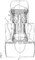
第1図は、ガスタービンエンジンの側面の部分破断図である。
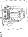
第2図は、タービンシュラウドアセンブリを含むステータアセンブリを有するタービンの側面図である。
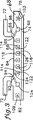
第3図は、シュラウドセグメントの側面図であり、点線は冷却チャネルを示している。
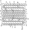
第4図は、シュラウドセグメントの上から見た断面図であり、曲折流路と横方向流路を図示している。
第5図は、シュラウドセグメントの上面図であり、冷却チャネルの入口を示している。
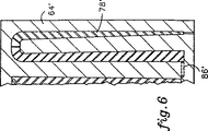
第6図は、シュラウドセグメントの一部の上面図であり、下流に向かって先細となった曲折チャネルを示している。
発明の好適実施態様
第1図にガスタービンエンジン12を示す。ガスタービンエンジン12は、長手方向軸16を中心として設けられた環状流路14を含んでいる。軸に沿って、コンプレッサ18、燃焼器22、及びタービン24が隔置されており、流路14はそれらを順に通って延在している。タービン24は複数のロータアセンブリ26を含んでおり、それらは流路14を通って流れる作動流体と相互作用し、作動流体からロータアセンブリ26へとエネルギーが移動する。このエネルギーの一部は、タービン24とコンプレッサ18を接続する一対の回転シャフト28を介してコンプレッサ18に戻され、それによってコンプレッサ18が作動流体を圧縮するときに必要なエネルギーが供給される。
第2図を参照されたい。ロータアセンブリ32が、上流側ベーンアセンブリ34と下流側ベーンアセンブリ36との間に位置している。このロータアセンブリ32は、回転ディスク38を含んでおり、回転ディスク38から複数の動翼42が径方向に延在している。動翼42の各々は、ルート部44、先端48を有するエアフォイル部46、及び内側プラットフォーム52を含んでいる。ルート部44によって、動翼42はロータアセンブリ32の回転中にディスク38から外れないよう保持される。エアフォイル部46は、流路14を横切って径方向に延在しており、タービンを通って流れる作動流体と相互作用する流路面54を有している。内側プラットフォーム52は動翼42から横方向に延在しており、周方向に隣接する動翼のプラットフォームと整合して、径方向内側流路面56を形成している。径方向内側流路面56は、作動流体がエアフォイル部46の流路面54上を流れるのを促進する。
ロータアセンブリ32の径方向外側には、その周囲を囲むようにタービンシュラウド58が周方向に延在している。タービンシュラウド58によって画定される径方向外側流路面62は、動翼42の先端48と径方向に極めて近接している。流路面62は、作動流体が径方向外向きに流れるのを阻止し、作動流体がエアフォイル部46の流路面54上を流れるように働く。作動流体は、タービンシュラウド58の流路面62とプラットフォーム部52の流路面56とによって形成される環状流路内を流れ、この流路を横切る動翼42と効率よく相互作用する。
タービンシュラウド58は、流路14の周りに周方向に隔置された複数のシュラウドセグメント64を含んでいる。第3図乃至第5図に示すように、各シュラウドセグメント64は、複数のフック72を有する基板68と、コーティング層74を含んでいる。フック72はシュラウドセグメント64をタービンシュラウド58の隣接する構造体に保持する手段として働く。コーティング層74は、タービンを流れる高温ガスからシュラウドセグメントを保護するための熱障壁コーティングと、ロータアセンブリの回転中に動翼の先端と係合する摩耗可能コーティング(abradable coating)を組み合わせたものである。
各シュラウドセグメント64には、基板68内を延在する複数の冷却チャネル76が形成されている。これらの複数のチャネル76には、シュラウドセグメント64のリーディングエッジに沿った曲折チャネル78と、シュラウドセグメント64のトレーリングエッジに沿った曲折チャネル82と、それらの間に設けられた複数の横方向チャネル(lateral channel)84が含まれる。曲折チャネル78は、シュラウドセグメント64の外側面とダクト86を介して連通している。そのため、ダクト86は外側面に入口88を有している。入口88はリーディングエッジフック72のすぐ内側に配置されており、ダクト86はフック72の下を通って延在している。ダクト86によって、リーディングエッジに沿ったシーリング(sealing)を損なうことなく曲折チャネル78内に冷却流体を流すのに都合の良い機構が得られており、フック72の下にキャビティを延在させる場合必要であった、フック72を基板68から外向きに伸ばすことも必要なくなっている。トレーリングエッジの曲折チャネル82もリーディングエッジの曲折チャネル78と同様に、入口94を有するダクト92を備えている。
曲折チャネル78は第1流路96と、この第1流路96の外側に位置する第2流路98と、これら2つの流路96、98を結ぶベンド102と、出口103を含んでいる。トレーリングエッジに沿った曲折チャネル82も、曲折チャネル78と同様に、第1流路104、第2流路106、これら2つの流路104と106をつなぐベンド108、及び出口109を含んでいる。曲折チャネル78、82はどちらも、その長手方向に沿って分布されたトリップストリップ(trip strip)112を含んでいる。トリップストリップ112は、チャネル78及び82を流れる流体の流れを乱し、渦流的な乱流(regenerative turbulant flow)を生成して、流体と基板68との間の熱伝達を高める働きをする。
横方向チャネル84は、一対のフック72の間において横方向に延在しており、横方向チャネル114からなる第1セットと、横方向チャネル116からなる第2セットを含んでいる。第1セットの横方向チャネル114は、シュラウドセグメント64の一方の横側エッジ(lateral edge)119に沿って外側面に設けられた入口118と、シュラウドセグメント64の他方の横側エッジ120に設けられた出口122を有している。第2セットの横方向チャネル116は、横側エッジ120に沿って設けられた入口124と、他方の横側エッジ120に設けられた出口126を有している。第1セットのチャネル114と第2セットのチャネル116は互いに交互に配置され、各横方向チャネル84は、他方のセットに属する横方向チャネルの一つと間に位置する境界壁128を共有している。曲折チャネル78、82と同様に、横方向チャネル84は乱流を生成するべく長手方向に沿って分布されたトリップストリップ132を含んでいる。また、横方向チャネル84は、中を流れる流体のレイノルズ数を制御するべく、入口から出口へ向かって先細となっている。レイノルズ数が増加すると、チャネル内を流れる流体と基板との間の熱伝達も増加する。
曲折チャネルは概ね一定の断面積を有するものとして示されているが、曲折チャネル内を流れる流体のレイノルズ数を制御するため先細のチャネルを用いてもよい。本例では、シュラウドセグメントのリーディングエッジ及びトレーリングエッジに沿って形成されたこれらのチャネル内におけるレイノルズ数の制御は必要であるとは思われないが、応用例によっては、第6図に示すように、リーディングエッジ及びトレーリングエッジ領域における基板からの熱伝達をできるだけ高めるためにこの特徴が必要となることもあり得る。第6図に示されているシュラウドセグメント64′は、ダクト86′を有する端部から他方の端部へと先細となった曲折チャネル78′を含んでいる。
動作中、冷却流体はステータアセンブリを通って流れ、シュラウドセグメント64は外側面に当たる。この冷却流体の少なくとも一部は曲折チャネル78、82の入口88、94、及び横方向チャネル84の入口118、112に流入する。入口88に流入した冷却流体は、ダクト86を通って、第1曲折チャネル78へと流れる。この冷却流体はトリップストリップ112と相互作用しつつ、第1流路96、ベンド102、及び第2流路98を通って流れる。冷却流体は出口103を通って第2流路102から放出される。第2流路98から放出された流体は、隣接するシュラウドセグメント64間のギャップ(即ち、セグメント間ギャップ)内へと流れて高温ガスをパージし、高温ガスがギャップ内へ流れ込むのを防止する。入口94から流入する冷却流体は、概ね同様に、ダクト92を通って、トレーリングエッジに沿って曲折チャネル82内を流れ、シュラウドセグメント64の反対側の横側エッジ119に沿ったセグメント間ギャップ内へと放出される。
冷却流体の別の一部は、入口118、124から流入し、横方向チャネル84内を流れる。第1セットの横方向チャネル114の各々は、第2セットの横方向チャネル116の一つと隣接しているため、隣接する横方向チャネル84では冷却流体は逆方向に流れる。冷却流体はトリップストリップ132と相互作用し、乱流が生成される。また、先細となっていることによって、流体のレイノルズ数は横方向チャネル84を通して制御されている。冷却流体は出口122、126を通って横方向チャネル84から放出され、シュラウドセグメント64のいずれかの側のセグメント間ギャップ内に流入し、ガスが溜まらないようにパージする。
チャネル78、82、84をリーディングエッジ領域及びトレーリングエッジ領域を含む基板68の全体に設けることによって、基板64におけるホットスポットの生成が大幅に低減される。更に、出口103、109、122、126から放出される流体のセグメント間ギャップへの吹き込みにより、高温ガスがセグメント間ギャップ内に流れ込んだり、そこに滞留したりしてシュラウドセグメント64の横側エッジ119、120が損傷される可能性が低減される。
このような曲折チャネル78、82を設けることによって、基板64のリーディングエッジ領域及びトレーリングエッジ領域へと導かれる冷却流体が効率よく活用される。これらの領域は、動翼42のブレードポンピング効果(blade pumping effect)のため、シュラウドセグメント64の動翼通過領域と比べて、熱負荷は低い。ブレードポンピングは、作動流体が外向きに流れてシュラウドセグメントの動翼通過領域に衝当するように作用する。リーディングエッジは動翼42の上流側にあり、最も高温のガス流路流体(gas path fluid)を有する流路14の領域内にあるが、シュラウドセグメント64のリーディングエッジ周りにおいて漏出する冷却流体によってリーディングエッジ領域を覆うように冷却流体の膜が形成される(第2図の矢印134によって図示)。また、トレーリングエッジ領域は動翼42の下流側にあり、動翼42にエネルギーを与えた後のガス流路流体に曝される。従って、リーディングエッジ領域及びトレーリングエッジ領域は、シュラウドセグメント64の動翼通過領域に比べると冷却効果は小さくてよく、曲折チャネル78、82をこれらの領域で使用し、冷却流体を効率よく活用することができる。
シュラウドセグメント64は鋳造により製造することができる。この手順は、チャネル78、82、84を作るための中子を形成する過程と、その中子を中心として基板68を鋳造する過程を含む。鋳造過程が終了すると、鋳造のあいだチャネル用中子を保持するための中子支持手段として横側エッジに沿って形成された鋳造孔は、出口として使用されるものを除いて埋められる。入口88、94、118、124及びダクト86、92は、例えば放電加工のような従来の技術によって外側面に形成される。フック72及びシールランド(seal land)は基板68上に加工形成され、その後コーティング層74が流路面上に形成される。
本発明をその実施例に関して説明してきたが、当業者には理解されるように、本発明の思想及び範囲を逸脱することなく様々な変更、省略及び追加が可能である。 The present invention relates to a gas turbine engine. In particular, it relates to the turbine shroud segment of such an engine.
BACKGROUND ART An axial flow gas turbine engine includes a compressor, a combustor, and a turbine arranged in order along a longitudinal axis, and an annular flow path passes through the compressor, combustor, and turbine. Extending in the axial direction. The compressor is equipped with a rotating blade that interacts with the incoming working fluid and compresses it. Part of the compressed working fluid enters the combustor and is mixed with fuel and ignited. Combustion products or hot gases flow through the turbine. In the turbine, vanes and moving blades are alternately arranged, and the energy of the hot gas moves to the moving blades. Part of this energy is returned to the compressor section via the rotating shaft.
The hot gas flows in an annular space defined by the inner and outer turbine shrouds so that the hot gas flowing through the turbine and the blades interact as efficiently as possible. The inner turbine shroud typically consists of a plurality of platforms formed integrally with the blade. These platforms are aligned with adjacent blade platforms to form an inner flow surface. The outer shroud is typically a ring-like assembly that is located radially outwardly adjacent to the outer tip of the blade. The outer shroud includes a plurality of arcuate segments that are spaced circumferentially to form an outer flow surface.
Since the shroud segments are in direct contact with the hot gas, some cooling is required to keep these shroud segments within the allowable temperature range. Cooling methods include impingement cooling in which the cooling fluid is applied to the radially outer surface or back surface of the shroud segment, and a cooling fluid thin film is formed over the entire flow surface of the shroud segment by providing cooling holes in the shroud segment. There is film cooling that forms the film.
Both impact cooling and film cooling were sufficient in most situations, but with the advancement of gas turbine engines, the gas flowing through the turbine has become even hotter, and the higher temperature of this working fluid makes it more efficient. There is a need for improved cooling methods. One such method recently disclosed is US Pat. No. 5,375,973 (Title “Turbine Blade Outer Air Seal With Optimized Cooling and Method of Fabrication”) granted December 27, 1994. Some have been disclosed. In accordance therewith, a cooling channel is disclosed that extends laterally through a shroud segment in a counter flow array configuration. These channels include an inlet provided in the backside of the shroud segment and an outlet that discharges cooling fluid into the inter-segment gap. Further, in order to control the Mach number of the fluid flowing in the channel, a portion tapered in the flow direction is included.
In the above-described configuration, there is a limit to the ability to supply cooling fluid to the leading edge (leading edge) region and the trailing edge (rear edge) region of the shroud segment. Each shroud segment has holding means adjacent to the leading and trailing edge regions to hold itself in place within the stator structure. Typically, these retaining means are rails or hooks that extend radially outward from the back surface of the shroud segment and extend laterally along the edges. These hooks and rails prevent cooling fluid from flowing into this area and hitting the backside near the edge. The film cooling channel can be angled to direct some of the cooling fluid to these areas, but the film cooling channel is formed at a shallow enough angle to achieve full coverage. That is not practical. Eventually, these hooks and rails prevent cooling fluid from flowing directly into the lateral channel below them and extend across the leading and trailing edge regions from the back to the bottom of the hooks and rails. An existing cavity is required. The hooks and rails then extend further outward from the shroud segment, resulting in increased shroud segment weight and stiffness.
A shroud segment for a gas turbine engine as defined in the precharacterizing portion of claim 1, which is an independent claim, is disclosed in FR-A-2 359 976. The shroud segment of FR-A-2 359 976 has a bent channel formed along the trailing edge. The inlet duct is connected to the outer flow path of the bent channel, and the inner flow path of the bent channel is connected to outlet orifice means provided on the inward flow surface of the shroud segment.
Despite the techniques described above, researchers and engineers working under the guidance of the applicant have developed an efficiently coolable turbine shroud segment for gas turbine engines.
Disclosure of the invention A turbine shroud segment according to the invention comprises a curved channel extending along at least one of the axial edges, as defined by the independent claims. The bent channel includes an inner channel, an outer channel, and a duct. The outer channel is located closest to the edge, and the outer channel and the inner channel are in communication. The duct extends from the opening formed in the back surface of the shroud segment to the inner flow path so that cooling air can flow into the bent flow path.
Due to this feature of the bent channel, the edges of the shroud segment are convectively cooled. Since this area of the shroud segment is outside the holding means (eg hooks or rails), conventional methods such as impact cooling and / or film cooling have not been applicable. The cooling fluid enters from the duct, flows through the bent channel and is discharged from the outlet.
According to a particular embodiment of the invention, the shroud segment includes a bent channel along the leading edge, a second bent channel along the trailing edge, and a plurality of lateral channels. The shroud segment also includes a front holding means and a rear holding means, and these two holding means extend from the back surface and are separated in the axial direction. The first bent channel is located in front of the front holding means, and its duct extends from the point behind the front holding means to the inner flow path. The second bent channel is located behind the rear holding means, and its duct extends from a point in front of the rear holding means to the second inner flow path. The lateral channels comprise a first set of channels having an inlet provided along the lateral edge of the shroud segment and an outlet provided at the opposite lateral edge, and the first set of channels. And a second set of channels having inlets and outlets arranged opposite to the channels. Each of the first set of channels is adjacent to one of the second set of channels, so that the cooling fluid flowing through each lateral channel is opposite in direction to the cooling fluid flowing in the adjacent channel. It becomes.
By using a combination of leading and trailing edge channels along with a plurality of alternating lateral channels with opposite flow directions, hot spots generated in the shroud segment can be greatly reduced. The transverse channel also greatly improves the cooling effect of the blade passage region of the shroud segment. This region is exposed to the highest heat load as a result of the temperature profile of the working fluid flowing into the turbine having a parabolic characteristic and the working fluid being pushed outward by the blades. The leading and trailing edge regions, which have a lower thermal load but are extremely difficult to perform impingement cooling or film cooling from the film cooling holes, are convectively cooled by the bend channel. Thus, convection cooling is possible over the entire axial direction of the shroud segment.
These and other features and advantages of the present invention will become more apparent from the following detailed description of exemplary embodiments, as illustrated in the accompanying drawings.
[Brief description of the drawings]
FIG. 1 is a partially cutaway side view of a gas turbine engine.
FIG. 2 is a side view of a turbine having a stator assembly that includes a turbine shroud assembly.
FIG. 3 is a side view of the shroud segment, with the dotted lines indicating the cooling channels.
FIG. 4 is a cross-sectional view of the shroud segment as viewed from above, and shows a bent flow path and a lateral flow path.
FIG. 5 is a top view of the shroud segment showing the inlet of the cooling channel.
FIG. 6 is a top view of a portion of the shroud segment, showing the bend channel tapering downstream.
Preferred embodiment of the invention Figure 1 shows a
See FIG. A
A
The
Each
The
The
Although the bent channel is shown as having a generally constant cross-sectional area, a tapered channel may be used to control the Reynolds number of the fluid flowing in the bent channel. In this example, control of the Reynolds number in these channels formed along the leading and trailing edges of the shroud segment may not be necessary, but depending on the application, as shown in FIG. In addition, this feature may be necessary to maximize the heat transfer from the substrate in the leading and trailing edge regions. The shroud segment 64 'shown in FIG. 6 includes a bend channel 78' that tapers from the end having the duct 86 'to the other end.
In operation, cooling fluid flows through the stator assembly and the
Another portion of the cooling fluid enters from the
By providing the
By providing
The
Although the invention has been described with reference to embodiments thereof, it will be appreciated by those skilled in the art that various modifications, omissions, and additions can be made without departing from the spirit and scope of the invention.
Claims (12)
前記シュラウドセグメント(64)は、
径方向内側面と、
前記径方向内側面と相反して配置された径方向外側面(66)と、
リーディングエッジとトレーリングエッジを画定する一対の軸側エッジと、
一対の横側エッジ(119、120)と、
前記リーディングエッジに隣接して前記外側面(66)から延在する第1保持手段(72)と、
前記トレーリングエッジに隣接して前記外側面(66)から延在する第2保持手段(72)と、
前記軸側エッジの一方に隣接して延在する前記保持手段(72)の外側においてそのエッジに沿って延在する外側流路(98)と、前記外側流路(98)の内側に位置して前記外側流路(98)と連通した内側流路(96)と、隣接する保持手段(72)の間の外側面(66)から延在するダクト(86)と、前記外側流路(96)と連通した出口(103)とを含む曲折チャネル(78;78′)とを含んでおり、
前記外側面(66)上に吹き込まれた前記冷却流体の一部が前記曲折チャネル(78;78′)を通って流れるように、前記ダクト(86)によって前記シュラウドセグメント(64)の外側面(66)と前記曲折チャネル(78;78′)とが連通されており、
前記ダクト(86)は前記曲折チャネル(78;78′)の前記内側流路(96)へと延在しており、前記出口(103)は前記外側流路(98)とつながっており、更に、
前記出口(103)は、前記シュラウドセグメント(64)の前記横側エッジ(119、120)の一方(120)に設けられ、前記一方の横側エッジ(120)と前記外側流路(98)との間に延在して、それらを連通していることを特徴とするシュラウドセグメント。A rotor assembly (32) having an annular flow path (14) formed about a longitudinal axis (16) and a plurality of blades (42) extending radially across the flow path (14); A shroud including a plurality of shroud segments (64) spaced circumferentially to form a flow path surface (62) radially outward of the bucket (42) and defining a portion of the flow path (14) A shroud segment (64) for a gas turbine engine (12) having an assembly (38) and means for injecting cooling fluid onto the plurality of shroud segments (64);
The shroud segment (64)
A radially inner surface;
A radially outer surface (66) disposed opposite to the radially inner surface;
A pair of axial edges defining a leading edge and a trailing edge;
A pair of lateral edges (119, 120);
First retaining means (72) extending from the outer surface (66) adjacent to the leading edge;
Second retaining means (72) extending from the outer surface (66) adjacent to the trailing edge;
An outer channel (98) extending along the edge outside the holding means (72) extending adjacent to one of the axial edges, and an inner side of the outer channel (98). An inner channel (96) communicating with the outer channel (98), a duct (86) extending from an outer surface (66) between adjacent holding means (72), and the outer channel (96). ) And a bent channel (78; 78 ') including an outlet (103) in communication with
The outer surface of the shroud segment (64) by the duct (86) so that a portion of the cooling fluid blown onto the outer surface (66) flows through the bent channel (78; 78 '). 66) and the bent channel (78; 78 ') are communicated with each other,
The duct (86) extends to the inner channel (96) of the bent channel (78; 78 '), the outlet (103) is connected to the outer channel (98), and ,
The outlet (103) is provided on one (120) of the lateral edges (119, 120) of the shroud segment (64), the one lateral edge (120) and the outer flow path (98) A shroud segment that extends between and communicates with each other.
前記外側面(66)上に吹き込まれた前記冷却流体の一部が前記第2曲折チャネル(82)を通って流れるように、前記ダクト(92)によって前記シュラウドセグメント(64)の外側面(66)と前記第2曲折チャネル(82)とが連通されていることを特徴とする請求項1に記載のシュラウドセグメント。An outer flow path (106) extending along the edge outside the holding means (72) extending adjacent to the other axial edge, and an inner flow located inside the outer flow path (106) A second bend channel (82) further comprising a passage (104) and a duct (92) extending from a position inside an adjacent retaining means (72) to the inner flow path (104);
The duct (92) causes the outer surface (66) of the shroud segment (64) so that a portion of the cooling fluid blown onto the outer surface (66) flows through the second bend channel (82). 2) and the second bend channel (82) in communication with each other.
前記複数の横方向チャネル(64)は前記第1及び第2保持手段(72)の内側に配置されており、各横方向チャネル(84)は隣接する横方向チャネル(84)からそれらの間の壁(128)によって分離されており、各横方向チャネル(84)は前記シュラウドセグメント(64)の裏面に設けられた入口(118、124)と前記シュラウドセグメント(64)の横側エッジ(119、120)に設けられた出口(122、126)とを有しており、
前記外側面(66)上に吹き込まれた冷却流体の一部が前記横方向チャネル(84)を通って流れて前記シュラウドセグメント(64)の前記横側エッジ(119、120)に沿って前記横方向チャネル(84)から放出されるように、前記入口(118、124)によって前記シュラウドセグメント(64)の前記外側面(66)と前記横方向チャネル(84)とが連通されていることを特徴とする請求項1に記載のシュラウドセグメント。A plurality of lateral channels (84) extending laterally through the shroud segment (64);
The plurality of lateral channels (64) are disposed inside the first and second retaining means (72), and each lateral channel (84) is between adjacent lateral channels (84) between them. Each lateral channel (84) is separated by a wall (128) and an inlet (118, 124) provided on the back side of the shroud segment (64) and a lateral edge (119, 124) of the shroud segment (64). 120) and outlets (122, 126) provided in
A portion of the cooling fluid blown onto the outer surface (66) flows through the lateral channel (84) and along the lateral edges (119, 120) of the shroud segment (64). The outer surface (66) of the shroud segment (64) and the lateral channel (84) communicate with each other by the inlets (118, 124) so as to be discharged from the directional channel (84). The shroud segment according to claim 1.
前記第1セットの横方向チャネル(114)は、前記横側エッジの一方(119)に沿って設けられた入口(118)と他方の横側エッジ(120)に設けられた出口(126)とを有し、
前記第2セットの横方向チャネル(116)は、前記他方の横側エッジ(120)に沿って設けられた入口(124)と、前記一方の横側エッジ(119)に設けられた出口(122)とを有し、
前記第1セットの横方向チャネル(114)の各々は、前記第2セットの横方向チャネル(116)の一つと隣接しており、これら複数の横方向チャネル(84)の各々を流れる冷却流体は、隣接する横方向チャネル(84)を流れる冷却流体と逆方向に流れることを特徴とする請求項3に記載のシュラウドセグメント。The plurality of transverse channels (84) includes a first set of transverse channels (114) and a second set of transverse channels (116);
The first set of lateral channels (114) includes an inlet (118) provided along one of the lateral edges (119) and an outlet (126) provided at the other lateral edge (120). Have
The second set of lateral channels (116) includes an inlet (124) provided along the other lateral edge (120) and an outlet (122) provided at the one lateral edge (119). )
Each of the first set of transverse channels (114) is adjacent to one of the second set of transverse channels (116), and the cooling fluid flowing through each of the plurality of transverse channels (84) is The shroud segment of claim 3, wherein the shroud segment flows in a direction opposite to the cooling fluid flowing through adjacent lateral channels (84).
前記外側面(66)上に吹き込まれた前記冷却流体の一部が前記第2曲折チャネル(82)を通って流れるように、前記ダクト(92)によって前記シュラウドセグメント(64)の外側面(66)と前記第2曲折チャネル(82)とが連通されていることを特徴とする請求項4に記載のシュラウドセグメント。An outer flow path (106) extending along the edge outside the holding means (72) extending adjacent to the other axial edge, and an inner flow located inside the outer flow path (106) A passage (104), a duct (92) extending from a position inside an adjacent holding means (72) to the inner flow path (104), and an outlet (109) communicating with the outer flow path (106) A second bend channel (82) comprising:
The duct (92) causes the outer surface (66) of the shroud segment (64) so that a portion of the cooling fluid blown onto the outer surface (66) flows through the second bend channel (82). 5) and the second bend channel (82) in communication with each other.
Applications Claiming Priority (3)
| Application Number | Priority Date | Filing Date | Title |
|---|---|---|---|
| US08/220,316 | 1994-03-30 | ||
| US08/220,316 US5486090A (en) | 1994-03-30 | 1994-03-30 | Turbine shroud segment with serpentine cooling channels |
| PCT/US1995/003567 WO1995027126A1 (en) | 1994-03-30 | 1995-03-21 | Turbine shroud segment with serpentine cooling channels |
Publications (2)
| Publication Number | Publication Date |
|---|---|
| JPH09511304A JPH09511304A (en) | 1997-11-11 |
| JP3671981B2 true JP3671981B2 (en) | 2005-07-13 |
Family
ID=22823069
Family Applications (1)
| Application Number | Title | Priority Date | Filing Date |
|---|---|---|---|
| JP52574495A Expired - Fee Related JP3671981B2 (en) | 1994-03-30 | 1995-03-21 | Turbine shroud segment with bent cooling channel |
Country Status (5)
| Country | Link |
|---|---|
| US (1) | US5486090A (en) |
| EP (1) | EP0753100B1 (en) |
| JP (1) | JP3671981B2 (en) |
| DE (1) | DE69502282T2 (en) |
| WO (1) | WO1995027126A1 (en) |
Families Citing this family (71)
| Publication number | Priority date | Publication date | Assignee | Title |
|---|---|---|---|---|
| EP0694677B1 (en) * | 1994-07-29 | 1999-04-21 | United Technologies Corporation | Seal for a gas turbine engine |
| US5538393A (en) * | 1995-01-31 | 1996-07-23 | United Technologies Corporation | Turbine shroud segment with serpentine cooling channels having a bend passage |
| US5609469A (en) * | 1995-11-22 | 1997-03-11 | United Technologies Corporation | Rotor assembly shroud |
| EP1041247B1 (en) * | 1999-04-01 | 2012-08-01 | General Electric Company | Gas turbine airfoil comprising an open cooling circuit |
| US6761534B1 (en) | 1999-04-05 | 2004-07-13 | General Electric Company | Cooling circuit for a gas turbine bucket and tip shroud |
| US6241467B1 (en) | 1999-08-02 | 2001-06-05 | United Technologies Corporation | Stator vane for a rotary machine |
| US6254333B1 (en) | 1999-08-02 | 2001-07-03 | United Technologies Corporation | Method for forming a cooling passage and for cooling a turbine section of a rotary machine |
| US6432216B1 (en) | 2000-02-09 | 2002-08-13 | Whirlpool Corporation | Soil sensing system for a dishwasher |
| FR2857406B1 (en) * | 2003-07-10 | 2005-09-30 | Snecma Moteurs | COOLING THE TURBINE RINGS |
| US20060078429A1 (en) * | 2004-10-08 | 2006-04-13 | Darkins Toby G Jr | Turbine engine shroud segment |
| US7306424B2 (en) * | 2004-12-29 | 2007-12-11 | United Technologies Corporation | Blade outer seal with micro axial flow cooling system |
| US7284954B2 (en) * | 2005-02-17 | 2007-10-23 | Parker David G | Shroud block with enhanced cooling |
| US7520715B2 (en) * | 2005-07-19 | 2009-04-21 | Pratt & Whitney Canada Corp. | Turbine shroud segment transpiration cooling with individual cast inlet and outlet cavities |
| US20070048122A1 (en) * | 2005-08-30 | 2007-03-01 | United Technologies Corporation | Debris-filtering technique for gas turbine engine component air cooling system |
| US7621719B2 (en) * | 2005-09-30 | 2009-11-24 | United Technologies Corporation | Multiple cooling schemes for turbine blade outer air seal |
| US7448850B2 (en) * | 2006-04-07 | 2008-11-11 | General Electric Company | Closed loop, steam cooled turbine shroud |
| US7665960B2 (en) | 2006-08-10 | 2010-02-23 | United Technologies Corporation | Turbine shroud thermal distortion control |
| US7771160B2 (en) * | 2006-08-10 | 2010-08-10 | United Technologies Corporation | Ceramic shroud assembly |
| JP5078341B2 (en) * | 2006-12-15 | 2012-11-21 | 三菱重工業株式会社 | Turbine blade ring structure and assembly method thereof |
| US7874792B2 (en) * | 2007-10-01 | 2011-01-25 | United Technologies Corporation | Blade outer air seals, cores, and manufacture methods |
| US8061979B1 (en) | 2007-10-19 | 2011-11-22 | Florida Turbine Technologies, Inc. | Turbine BOAS with edge cooling |
| US8366383B2 (en) * | 2007-11-13 | 2013-02-05 | United Technologies Corporation | Air sealing element |
| US8177492B2 (en) * | 2008-03-04 | 2012-05-15 | United Technologies Corporation | Passage obstruction for improved inlet coolant filling |
| US7942188B2 (en) * | 2008-03-12 | 2011-05-17 | Vent-Tek Designs, Llc | Refractory metal core |
| EP2159381A1 (en) * | 2008-08-27 | 2010-03-03 | Siemens Aktiengesellschaft | Turbine lead rotor holder for a gas turbine |
| US8365405B2 (en) | 2008-08-27 | 2013-02-05 | United Technologies Corp. | Preforms and related methods for repairing abradable seals of gas turbine engines |
| US8317461B2 (en) * | 2008-08-27 | 2012-11-27 | United Technologies Corporation | Gas turbine engine component having dual flow passage cooling chamber formed by single core |
| US8313301B2 (en) * | 2009-01-30 | 2012-11-20 | United Technologies Corporation | Cooled turbine blade shroud |
| US8740551B2 (en) * | 2009-08-18 | 2014-06-03 | Pratt & Whitney Canada Corp. | Blade outer air seal cooling |
| US8167546B2 (en) * | 2009-09-01 | 2012-05-01 | United Technologies Corporation | Ceramic turbine shroud support |
| JP5791232B2 (en) * | 2010-02-24 | 2015-10-07 | 三菱重工航空エンジン株式会社 | Aviation gas turbine |
| US8535006B2 (en) | 2010-07-14 | 2013-09-17 | Siemens Energy, Inc. | Near-wall serpentine cooled turbine airfoil |
| US8727704B2 (en) | 2010-09-07 | 2014-05-20 | Siemens Energy, Inc. | Ring segment with serpentine cooling passages |
| US9022736B2 (en) | 2011-02-15 | 2015-05-05 | Siemens Energy, Inc. | Integrated axial and tangential serpentine cooling circuit in a turbine airfoil |
| US8632298B1 (en) * | 2011-03-21 | 2014-01-21 | Florida Turbine Technologies, Inc. | Turbine vane with endwall cooling |
| US9017025B2 (en) | 2011-04-22 | 2015-04-28 | Siemens Energy, Inc. | Serpentine cooling circuit with T-shaped partitions in a turbine airfoil |
| US9017012B2 (en) | 2011-10-26 | 2015-04-28 | Siemens Energy, Inc. | Ring segment with cooling fluid supply trench |
| US9617866B2 (en) | 2012-07-27 | 2017-04-11 | United Technologies Corporation | Blade outer air seal for a gas turbine engine |
| US20140064969A1 (en) * | 2012-08-29 | 2014-03-06 | Dmitriy A. Romanov | Blade outer air seal |
| US9568009B2 (en) | 2013-03-11 | 2017-02-14 | Rolls-Royce Corporation | Gas turbine engine flow path geometry |
| GB201308605D0 (en) * | 2013-05-14 | 2013-06-19 | Rolls Royce Plc | A shroud arrangement for a gas turbine engine |
| US10077670B2 (en) | 2013-08-29 | 2018-09-18 | United Technologies Corporation | Blade outer air seal made of ceramic matrix composite |
| WO2015038341A1 (en) | 2013-09-11 | 2015-03-19 | United Technologies Corporation | Blade outer air seal having angled retention hook |
| WO2015138027A2 (en) | 2013-12-17 | 2015-09-17 | United Technologies Corporation | Meter plate for blade outer air seal |
| US10577963B2 (en) | 2014-01-20 | 2020-03-03 | United Technologies Corporation | Retention clip for a blade outer air seal |
| US10329916B2 (en) | 2014-05-01 | 2019-06-25 | United Technologies Corporation | Splayed tip features for gas turbine engine airfoil |
| EP3023596B1 (en) * | 2014-11-20 | 2019-01-02 | United Technologies Corporation | Internally cooled turbine platform |
| US10184356B2 (en) | 2014-11-25 | 2019-01-22 | United Technologies Corporation | Blade outer air seal support structure |
| US10329934B2 (en) | 2014-12-15 | 2019-06-25 | United Technologies Corporation | Reversible flow blade outer air seal |
| US9757936B2 (en) * | 2014-12-29 | 2017-09-12 | General Electric Company | Hot gas path component |
| US9963975B2 (en) * | 2015-02-09 | 2018-05-08 | United Technologies Corporation | Trip strip restagger |
| GB201508551D0 (en) | 2015-05-19 | 2015-07-01 | Rolls Royce Plc | A heat exchanger for a gas turbine engine |
| US10107128B2 (en) | 2015-08-20 | 2018-10-23 | United Technologies Corporation | Cooling channels for gas turbine engine component |
| EP3176371A1 (en) * | 2015-12-03 | 2017-06-07 | Siemens Aktiengesellschaft | Component for a fluid flow engine and method |
| US10221719B2 (en) * | 2015-12-16 | 2019-03-05 | General Electric Company | System and method for cooling turbine shroud |
| US10443426B2 (en) * | 2015-12-17 | 2019-10-15 | United Technologies Corporation | Blade outer air seal with integrated air shield |
| US10815827B2 (en) * | 2016-01-25 | 2020-10-27 | Raytheon Technologies Corporation | Variable thickness core for gas turbine engine component |
| US10202864B2 (en) * | 2016-02-09 | 2019-02-12 | United Technologies Corporation | Chevron trip strip |
| US10801345B2 (en) * | 2016-02-09 | 2020-10-13 | Raytheon Technologies Corporation | Chevron trip strip |
| US20170260873A1 (en) * | 2016-03-10 | 2017-09-14 | General Electric Company | System and method for cooling trailing edge and/or leading edge of hot gas flow path component |
| GB201612646D0 (en) * | 2016-07-21 | 2016-09-07 | Rolls Royce Plc | An air cooled component for a gas turbine engine |
| JP6746486B2 (en) * | 2016-12-14 | 2020-08-26 | 三菱日立パワーシステムズ株式会社 | Split ring and gas turbine |
| KR101873156B1 (en) * | 2017-04-12 | 2018-06-29 | 두산중공업 주식회사 | Turbine vane and gas turbine having the same |
| US11274569B2 (en) | 2017-12-13 | 2022-03-15 | Pratt & Whitney Canada Corp. | Turbine shroud cooling |
| US10533454B2 (en) | 2017-12-13 | 2020-01-14 | Pratt & Whitney Canada Corp. | Turbine shroud cooling |
| US10502093B2 (en) * | 2017-12-13 | 2019-12-10 | Pratt & Whitney Canada Corp. | Turbine shroud cooling |
| US10570773B2 (en) * | 2017-12-13 | 2020-02-25 | Pratt & Whitney Canada Corp. | Turbine shroud cooling |
| US10689997B2 (en) * | 2018-04-17 | 2020-06-23 | Raytheon Technologies Corporation | Seal assembly for gas turbine engine |
| US10989070B2 (en) * | 2018-05-31 | 2021-04-27 | General Electric Company | Shroud for gas turbine engine |
| US11365645B2 (en) * | 2020-10-07 | 2022-06-21 | Pratt & Whitney Canada Corp. | Turbine shroud cooling |
| KR102510535B1 (en) | 2021-02-23 | 2023-03-15 | 두산에너빌리티 주식회사 | Ring segment and turbo-machine comprising the same |
Family Cites Families (26)
| Publication number | Priority date | Publication date | Assignee | Title |
|---|---|---|---|---|
| US3728039A (en) * | 1966-11-02 | 1973-04-17 | Gen Electric | Fluid cooled porous stator structure |
| US3365172A (en) * | 1966-11-02 | 1968-01-23 | Gen Electric | Air cooled shroud seal |
| BE756582A (en) * | 1969-10-02 | 1971-03-01 | Gen Electric | CIRCULAR SCREEN AND SCREEN HOLDER WITH TEMPERATURE ADJUSTMENT FOR TURBOMACHINE |
| US3990807A (en) * | 1974-12-23 | 1976-11-09 | United Technologies Corporation | Thermal response shroud for rotating body |
| US4013376A (en) * | 1975-06-02 | 1977-03-22 | United Technologies Corporation | Coolable blade tip shroud |
| GB1605220A (en) * | 1975-10-11 | 1984-08-30 | Rolls Royce | Blade or vane for a gas turbine engine |
| US4353679A (en) * | 1976-07-29 | 1982-10-12 | General Electric Company | Fluid-cooled element |
| US4280792A (en) * | 1979-02-09 | 1981-07-28 | Avco Corporation | Air-cooled turbine rotor shroud with restraints |
| US4311432A (en) * | 1979-11-20 | 1982-01-19 | United Technologies Corporation | Radial seal |
| US4573865A (en) * | 1981-08-31 | 1986-03-04 | General Electric Company | Multiple-impingement cooled structure |
| US4573866A (en) * | 1983-05-02 | 1986-03-04 | United Technologies Corporation | Sealed shroud for rotating body |
| US4655044A (en) * | 1983-12-21 | 1987-04-07 | United Technologies Corporation | Coated high temperature combustor liner |
| US4650394A (en) * | 1984-11-13 | 1987-03-17 | United Technologies Corporation | Coolable seal assembly for a gas turbine engine |
| US4650395A (en) * | 1984-12-21 | 1987-03-17 | United Technologies Corporation | Coolable seal segment for a rotary machine |
| FR2597921A1 (en) * | 1986-04-24 | 1987-10-30 | Snecma | SECTORIZED TURBINE RING |
| US4752184A (en) * | 1986-05-12 | 1988-06-21 | The United States Of America As Represented By The Secretary Of The Air Force | Self-locking outer air seal with full backside cooling |
| GB2227965B (en) * | 1988-10-12 | 1993-02-10 | Rolls Royce Plc | Apparatus for drilling a shaped hole in a workpiece |
| JPH03213602A (en) * | 1990-01-08 | 1991-09-19 | General Electric Co <Ge> | Self cooling type joint connecting structure to connect contact segment of gas turbine engine |
| US5098257A (en) * | 1990-09-10 | 1992-03-24 | Westinghouse Electric Corp. | Apparatus and method for minimizing differential thermal expansion of gas turbine vane structures |
| US5088888A (en) * | 1990-12-03 | 1992-02-18 | General Electric Company | Shroud seal |
| US5169287A (en) * | 1991-05-20 | 1992-12-08 | General Electric Company | Shroud cooling assembly for gas turbine engine |
| US5165847A (en) * | 1991-05-20 | 1992-11-24 | General Electric Company | Tapered enlargement metering inlet channel for a shroud cooling assembly of gas turbine engines |
| US5205115A (en) * | 1991-11-04 | 1993-04-27 | General Electric Company | Gas turbine engine case counterflow thermal control |
| US5219268A (en) * | 1992-03-06 | 1993-06-15 | General Electric Company | Gas turbine engine case thermal control flange |
| US5375973A (en) * | 1992-12-23 | 1994-12-27 | United Technologies Corporation | Turbine blade outer air seal with optimized cooling |
| US5374161A (en) * | 1993-12-13 | 1994-12-20 | United Technologies Corporation | Blade outer air seal cooling enhanced with inter-segment film slot |
-
1994
- 1994-03-30 US US08/220,316 patent/US5486090A/en not_active Expired - Lifetime
-
1995
- 1995-03-21 JP JP52574495A patent/JP3671981B2/en not_active Expired - Fee Related
- 1995-03-21 EP EP95914151A patent/EP0753100B1/en not_active Expired - Lifetime
- 1995-03-21 WO PCT/US1995/003567 patent/WO1995027126A1/en not_active Ceased
- 1995-03-21 DE DE69502282T patent/DE69502282T2/en not_active Expired - Lifetime
Also Published As
| Publication number | Publication date |
|---|---|
| EP0753100A1 (en) | 1997-01-15 |
| JPH09511304A (en) | 1997-11-11 |
| US5486090A (en) | 1996-01-23 |
| DE69502282D1 (en) | 1998-06-04 |
| EP0753100B1 (en) | 1998-04-29 |
| DE69502282T2 (en) | 1998-12-24 |
| WO1995027126A1 (en) | 1995-10-12 |
Similar Documents
| Publication | Publication Date | Title |
|---|---|---|
| JP3671981B2 (en) | Turbine shroud segment with bent cooling channel | |
| US5538393A (en) | Turbine shroud segment with serpentine cooling channels having a bend passage | |
| JP2510573B2 (en) | Hot gas overheat protection device for gas turbine power plant | |
| US5649806A (en) | Enhanced film cooling slot for turbine blade outer air seals | |
| US7785067B2 (en) | Method and system to facilitate cooling turbine engines | |
| JP4486201B2 (en) | Priority cooling turbine shroud | |
| EP1927725B1 (en) | System to facilitate preferentially distributed recuperated film cooling of turbine shroud assembly | |
| EP1488078B1 (en) | Impingement cooling of gas turbine blades or vanes | |
| US20100098554A1 (en) | Blade for a rotor | |
| JPS6119804B2 (en) | ||
| JP2001050004A (en) | Airfoil with insulated tip | |
| JP3417417B2 (en) | Outer air seal device for gas turbine engine that can be cooled | |
| CA2602311C (en) | Method and system to facilitate enhanced local cooling of turbine engines | |
| EP1013882A2 (en) | Gas turbine engine internal air system | |
| JPS62195402A (en) | Shroud device controlling nose clearance of turbine rotor blade | |
| US7588412B2 (en) | Cooled shroud assembly and method of cooling a shroud | |
| JP3302370B2 (en) | External air seal for turbine blades with thin film cooling slots | |
| EP2631428A1 (en) | Turbine nozzle segment | |
| EP3976933A1 (en) | Heatshield for a gas turbine engine | |
| JPS6147289B2 (en) |
Legal Events
| Date | Code | Title | Description |
|---|---|---|---|
| TRDD | Decision of grant or rejection written | ||
| A01 | Written decision to grant a patent or to grant a registration (utility model) |
Free format text: JAPANESE INTERMEDIATE CODE: A01 Effective date: 20050405 |
|
| A61 | First payment of annual fees (during grant procedure) |
Free format text: JAPANESE INTERMEDIATE CODE: A61 Effective date: 20050412 |
|
| R150 | Certificate of patent or registration of utility model |
Free format text: JAPANESE INTERMEDIATE CODE: R150 |
|
| FPAY | Renewal fee payment (event date is renewal date of database) |
Free format text: PAYMENT UNTIL: 20080428 Year of fee payment: 3 |
|
| FPAY | Renewal fee payment (event date is renewal date of database) |
Free format text: PAYMENT UNTIL: 20090428 Year of fee payment: 4 |
|
| FPAY | Renewal fee payment (event date is renewal date of database) |
Free format text: PAYMENT UNTIL: 20100428 Year of fee payment: 5 |
|
| FPAY | Renewal fee payment (event date is renewal date of database) |
Free format text: PAYMENT UNTIL: 20110428 Year of fee payment: 6 |
|
| LAPS | Cancellation because of no payment of annual fees |