JP3671499B2 - Lighting device - Google Patents

Lighting device Download PDF

Info

Publication number
JP3671499B2
JP3671499B2 JP2829796A JP2829796A JP3671499B2 JP 3671499 B2 JP3671499 B2 JP 3671499B2 JP 2829796 A JP2829796 A JP 2829796A JP 2829796 A JP2829796 A JP 2829796A JP 3671499 B2 JP3671499 B2 JP 3671499B2
Authority
JP
Japan
Prior art keywords
fixed
fixed portion
locking
main body
lighting device
Prior art date
Legal status (The legal status is an assumption and is not a legal conclusion. Google has not performed a legal analysis and makes no representation as to the accuracy of the status listed.)
Expired - Fee Related
Application number
JP2829796A
Other languages
Japanese (ja)
Other versions
JPH09223407A (en
Inventor
智明 藤井
康則 米澤
Current Assignee (The listed assignees may be inaccurate. Google has not performed a legal analysis and makes no representation or warranty as to the accuracy of the list.)
Panasonic Electric Works Co Ltd
Original Assignee
Matsushita Electric Works Ltd
Priority date (The priority date is an assumption and is not a legal conclusion. Google has not performed a legal analysis and makes no representation as to the accuracy of the date listed.)
Filing date
Publication date
Application filed by Matsushita Electric Works Ltd filed Critical Matsushita Electric Works Ltd
Priority to JP2829796A priority Critical patent/JP3671499B2/en
Publication of JPH09223407A publication Critical patent/JPH09223407A/en
Application granted granted Critical
Publication of JP3671499B2 publication Critical patent/JP3671499B2/en
Anticipated expiration legal-status Critical
Expired - Fee Related legal-status Critical Current

Links

Images

Landscapes

  • Non-Portable Lighting Devices Or Systems Thereof (AREA)

Description

【0001】
【発明の属する技術分野】
本発明は、AC100Vコンセントがない場所であっても周囲を照明することができる照明装置に関するものである。
【0002】
【従来の技術】
近年、乾電池や充電式電池、バッテリー等の電源手段を電源として周囲の照明を行うことができる照明装置が提供されている。これらの照明装置は夜に周囲が暗くなると自動点灯したり、人が近くに来た場合にのみ点灯させる等のセンサーライトと称されるものである。これらの照明装置はAC100Vコンセントが配置されていない廊下、通路、玄関、物置等に設置されるものであり、予め住宅に設置されている照明装置では照明を行うことができない所に設置されることが多い。
【0003】
【発明が解決しようとする課題】
この種の電池式の照明装置はどこでも使用することができる利点がある。しかしながら、この種の電池式の照明装置は引っ掛け式又はねじ止めなどによる完全固定式により取付けられており、引っ掛け式では手等の体が触れる位置や、地震等の衝撃により照明器具本体が落下して怪我をするという問題があり、また、完全固定式では前記のような問題はないが、一度取付けると取り外しが困難又は取り外しに手間がかかるという問題がある。更に、上記引っ掛け式のものは取り外しことができると言えども、取り外して床や机や家具やその他の台等に載せて使用する場合には設置が不安定で、設定された姿勢での使用ができないという問題がある。
【0004】
本発明は上記の従来例の問題点に鑑みて発明したものであって、取付け、取り外しが容易で、しかも、取り外した場合に床や机や家具やその他の台等の上に載せて安定して設定された姿勢で使用でき、また、壁や天井等の取付け面に取付けた固定部に取付けた状態では人、地震等による衝撃があっても簡単に外れないように着脱でき、更に固定部に被固定部を取付けた状態で、回動自在な照明器具を回動させた場合に壁や天井等の取付け面からの突出長さを短くできる照明装置を提供することを課題とするものである。
【0005】
【課題を解決するための手段】
上記課題を解決するために、本発明の照明装置は、内部に電源手段1を収容した照明器具本体3と、照明器具本体3の背部から突出したアーム部13と、アーム部13と回動自在に軸支する軸受け部14を前面側に設けた被固定部2と、壁や天井等に固定されるものであって被固定部2を着脱自在に取付ける固定部5とを備えた照明装置において、軸受け部14又はアーム部13のいずれかに押圧手段により押圧される軸用突部16を設けると共にいずれか他方に軸用突部16が回動自在に嵌まり込むはまり込み部17を設けて軸用突部16とはまり込み部17とで回動部15を構成し、照明器具本体3の前面に対して直交する方向で照明器具本体3の側面を2分割する分割線Mを設定し、照明器具本体3を回動して分割線Mが被固定部2の前面と略平行となった状態で該分割線Mと被固定部2の前面との間に上記回動部15の回動中心が位置するように設定し、被固定部2を照明器具本体3の置き台4として成ることを特徴とするものである。このような構成とすることで、壁や天井等の取付け面12に取付けた固定部5に照明器具本体3の背面部に設けた被固定部2を取付けた状態で使用できるのはもちろん、照明器具本体3を取り外した状態で使用する場合には置き台4を兼用する被固定部2を床や机や家具やその他の台等の上に載置することで、照明器具本体3を安定して設定された姿勢で使用できることになる。しかも、照明器具本体3を回動部15を中心に回動することで、照明角度を広範囲に設定できるものである。また、被固定部2の前面に設けた軸受け部14又は照明器具本体3の背部から背方に突出したアーム部13のいずれかに押圧手段により押圧される軸用突部16を設けると共にいずれか他方に軸用突部16が回動自在に嵌まり込むはまり込み部17を設けて軸用突部16とはまり込み部17とで回動部15を構成し、照明器具本体3の前面に対して直交する方向で照明器具本体3の側面を2分割する分割線Mを設定し、照明器具本体3を回動して分割線が被固定部2の前面と略平行となった状態で該分割線Mと被固定部2の前面との間に回動部15の回動中心が位置するように設定してあるので、照明器具本体3を回動した場合における固定部5の前面からの突出長さを短くすることができることになる。更に、軸受け部14又はアーム部13のいずれかに押圧手段により押圧される軸用突部16を設けると共にいずれか他方に軸用突部16が回動自在に嵌まり込むはまり込み部17を設けて軸用突部16とはまり込み部17とで回動部15を構成するので、照明器具本体3の回動が自在でありながら任意の回動角度で固定できることになり、また、照明器具本体3を被固定部2から外すことも可能となるものである。
【0006】
また、固定部5に係止部6を設け、被固定部2に係止部6に係止される被係止部7を設けることも好ましい。このような構成とすることで、係止部6と被係止部7との係止により簡単に固定部6に被固定部2を取付けたり、あるいは係止を解除することで取り外すことができるものである。
【0007】
また、固定部5が所定の厚みを有し、該固定部5の側面に係止部6を設け、被固定部2に被係止部7を設け、被固定部2の固定部5に対する回転により被係止部7を係止部6に係止するように構成することも好ましい。このような構成とすることで、回転という簡単な手段で係止あるいは係止解除ができるものであり、また、照明器具に外力が作用する場合には通常直線的な外力が作用するものであって、このため外力が作用しても被固定部が回転しにくくて外力で不用意に係止が解除されにくいものである。
【0008】
また、被固定部2を固定部5に取付けた状態で設定以下の力では回転不能で且つ設定以上の力で回転可能とするロック手段8を設け、該ロック手段8が固定部5に設けられる凸部9を有したたわみ片10と、被固定部2に設けられた凸部9がはめ込まれる凹部11とで構成してあることも好ましい。このような構成とすることで、簡単な構成のロック手段8により係止が外れないようにできるものである。
【0009】
また、たわみ片10が被固定部2の回転方向に対して垂直方向に撓むように構成してあることも好ましい。このような構成とすることで、簡単な構造のロック手段8を構成できるものである。
【0010】
また、固定部5に被固定部2を取付けた状態で、壁、天井等の取付け面12に被固定部2が接触しないように設定してあることも好ましい。このような構成とすることで、固定部5に被固定部2を取付ける際に取付け面12を傷付けることなく、取付けができるものである。
【0011】
また、凹部11を貫通孔とし、凹部11の周囲をたわみ片10の凸部9が凹部11より突出するように内方に半球面状に凹んだ半球面状凹み11aとすることも好ましい。このような構成とすることで、半球面状凹み11a内に指を入れて凸部9を押すことで凸部9と凹部11との係合を外すことができ、ロック解除をして固定部5から被固定部2を取り外す操作が簡単にできることになる。
【0012】
【発明の実施の形態】
以下本発明の実施形態を添付図面に基づいて説明する。図1乃至図3に示すように照明器具本体3の背部には被固定部2が取付けてある。照明器具本体3は前ケース20と後ケース21とで外殻が形成してあり、前ケース20内に照明手段81が内装してあり、前ケース20の前面部に照明手段81からの光を拡散するためのレンズ部22が接着又は溶着により取付けてある。照明手段81は例えば複数個のLEDを図4に示すように一直線に配置して構成してある。前ケース20の外面部には更に照明手段81の入、切、自動等の動作手段(図示せず)のカバー24、及び室内の明暗を判断する手段(図示せず)のカバー26が嵌合により取付けてある。また、前ケース20内には人体検知手段27を含む回路部28が内装され、人体検知手段27が前ケース20の孔から露出しており、更に前ケース20内には電池等の電源手段1を保持するためのホルダー29が内装され、該ホルダー29には電池手段1との電気接続を行うための接点部30が設けてある。
【0013】
前ケース20には後ケース21がねじ31により取付けてある。後ケース21には電源蓋32がフック部33及び固定リブ33aにより後ケース21の開口部に着脱自在に取付けてあり、この電源蓋32を外して電源手段1の交換を行うものである。後ケース21か
ら背方に向けてアーム部13が突設してあり、該アーム部13を被固定部2の前面部に設けた軸受け部14に回動自在に取付けてある。
【0014】
被固定部2の前面部には図5に示すように、軸受け部14となる一対の突起が突設してあり、この軸受け部14にアーム部13が回動自在に取付けられるのである。
【0015】
すなわち、図5に示すように、軸受け部14又はアーム部13のいずれかに押圧手段65により押圧される軸用突部16を設けると共にいずれか他方に軸用突部16が回動自在に嵌まり込むはまり込み部17を設けて回動部15を構成してある(図5においては、軸受け部16側に押圧手段65により押圧される軸用突部16を設け、アーム部13の両側面に凹形状をしたはまり込み部17を設けてある)。図5において軸受け部16は半球状をしていて端部に鍔部16aを設けて構成してあり、該軸受け部16の半球状の部分を軸受け部14の内壁面部に設けた孔にはめ込んで軸受け部14内に内装したコイルスプリングにより構成した押圧手段65により軸用突部16を軸受け部14の内壁面部に設けた孔から突出する方向に押圧してある。
【0016】
ここで、鍔部16aの存在により軸用突部16が内壁面部に設けた孔から脱落しないようになっている。一方、アーム部13の両側面部は凹形状に凹ませてあってはまり込み部17が設けてあり、このはまり込み部17を構成する凹みの内面側の直径は図5(c)に示すように軸用突部16の半球状をした部分の外面側の直径よりも小さくなっており、このため図5(c)に示すようにはまり込み部17の開口縁の全周に半球状をした軸用突部16の外面が環状をした線状態で弾接し軸用突部16の先端部がはまり込み部17内に嵌まりこんで抜けにくいようになっている。このように弾性的に軸用突部16をはまり込み部17に押圧して軸支することで、アーム部13を回動した場合任意の回動角度で維持できるものである。また、アーム部13を大きな力で引くとアーム部13を軸受け部14か取り外すことができて、照明器具本体3自体を手で持って携帯用の照明器具として使用できるものである。
【0017】
被固定部2は後述のように天井や壁等の取付け面12に取付ける固定部5に着脱できるようになっていると共に、照明器具本体3を床や机や家具やその他の台等の載置面40の上に載置する場合の置き台4として兼用できるように被固定部2の後面(つまり下面)が置き面部2aとなっている。図1、図2、図3には置き台4である被固定部2の後面(つまり下面)の置き面部2aを床や机や家具やその他の台等の載置面40の上に載置して使用する場合の例を示している。
【0018】
照明器具本体3は被固定部2に対して回動部15を中心に図2(b)の矢印のように回動して照明エリア及び照明器具本体3の被固定部2に対する角度を変えることができるようになっている。被固定部2は図7(b)に示すように前面部から背方に略円筒状をした周壁部41を突設してあり、前面部の背面の中央部に環状のリブ42が突設してあり、更に、前面部に凹部11が形成してある。また、略円筒状をした周壁部41の背方端縁部には周方向に複数等分(実施形態においては3等分)する位置に被係止部7が内方に向けて突出してある。
【0019】
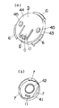
壁や天井等の取付け面12に取付けるための部材である固定部5は図7(a)に示すように円筒部43の前端部に前面板部44を設けてあり、前面板部44に設けた孔45からねじを挿入して壁や天井等の取付け面12に取付けるようになっている。固定部5の円筒部43の外周部には周方向に複数等分(実施形態においては3等分)する位置に係止部6が外方に向けて突出してある。
【0020】
そして、図10(a)に示すように背部に被固定部2を取付けた照明器具本体3を壁や天井等の取付け面12に対して取付けた固定部5に対して正面視で傾けた状態で、隣合う係止部6間に被係止部7が位置するようにして前方より円筒状をした被固定部2の周壁部41を固定部5の円筒部43に図10(b)のようにはめ込み、この状態で図10(b)の矢印のように固定部5に対して被固定部2を回動して図10(c)のようにするものであり、この図10(c)の状態では係止部6に被係止部7が係止され、被固定部2が固定部5に取付けられるものである。
【0021】
このようにして被固定部2が固定部5に対して回転により取付けられるのであるが、本
発明においては、被固定部2の固定部5に対する回転方向の位置決めと、クリック感による位置決めの確認と、取付け状態を保持するために被固定部2を固定部5に取付けた状態で設定以下の力では回転不能で且つ設定以上の力で回転可能とするロック手段8が設けてある。
【0022】
図7にはロック手段8の一例が示してあり、この実施形態においては、固定部5の前面板部44に凸部9を有したたわみ片10を設けると共に被固定部2の前面部に上記凸部9がはめ込まれる凹部11を設けてロック手段8が構成してある。そして、上記図10(a)、(b)、(c)の順番で被固定部2の被係止部7を固定部5の係止部6に係止して取付ける場合、図10(b)の状態では図11に示すように凸部9が被固定部2の前面部の背面に当たってたわみ片10がたわんでおり、このように凸部9が被固定部2の前面部の背面に当たった状態で被固定部2を図10(c)の状態まで回動すると、凸部9と凹部11とが対向し、図12に示すように凸部9がたわみ片10の弾性力により凹部11に嵌まりこんでクリック感による周方向の位置決めの確認ができると共にこのようにして周方向の位置決めがなされた状態において周方向の回転を規制するためのロックがなされるのである。
【0023】
ここで、たわみ片10は被固定部2の回転方向(図13(a)の矢印イ方向)に対して垂直方向(図13(a)の矢印ロ方向)に撓むようになっており、図13(c)に示すように、被固定部2の前面部の背面と凹部11の側面とのなす角度をαとした場合、凸部9のたわみ片10とのなす角度はα+βであって、α<α+βに設定してある。また、凸部9の先端面と側面とのなすコーナ部分がアール形状に面取りしてあり、これらのことにより、図13(b)のH方向に力を加えてロックを解除す場合に、力学上ロックが解除できる構造とすることができる。つまり、α=(α+β)の場合にはロック解除ができないものであるが、α<α+βに設定することでロック解除ができるのである。そして、βの角度を0°超〜180未満の範囲で調整することでロック解除の力を使い勝手、あるいは老若男女等使用者に応じ適正なロック解除力に設定することができるものである。また、凸部9の先端面と側面とのなすコーナ部分をアール形状に面取りすることで、違和感のないロック解除が行えるものである。
【0024】
壁や天井等の取付け面12に取付けた固定部5に被固定部2を取付けた状態で、図6に示すように壁、天井等の取付け面12に被固定部2の後端部が接触しないようになっている。ここで、被固定部2の背面に形成した環状のリブ42が固定部5の前面板部44に当接しており、このことにより被固定部2が固定部5側に移動して被固定部2の後端部が壁や天井等の取付け面12に当たらないようになっており、被固定部2が取付け面12に当たらないことで取付け面12が傷つかないようになっている。また、被固定部2の背面に形成した環状のリブ42が固定部5の前面板部44に当接することで、被固定部2を固定部5に被せて回動して着脱操作する際の接触面を少なくして回動による着脱操作が容易になるようになっている。
【0025】
すでに述べたように、照明器具本体3の背部から背方に向けてアーム部13が突出し、該アーム部13を被固定部2の前面側に設けた軸受け部14に前述のように回動自在に軸支して回動部15を構成しているが、照明器具本体3の前面に対して直交する方向で照明器具本体3の側面を2分割する分割線Mを設定した場合、図9(a)に示すように照明器具本体3を回動して分割線Mが被固定部2の前面と略平行となった状態で該分割線Mと被固定部2の前面との間に上記回動部15の回動中心が位置するように設定してある。つまり、アーム部13を軸受け部14に軸支するに当たり、図9(b)のように、分割線Mの延長線上にアーム部13と軸受け部14との回動中心を位置させた場合に、照明器具本体3を角度γ回動した場合における壁や天井等の取付け面12からの照明器具本体3の前端までのを長さL とした場合、図9(a)のように照明器具本体3を回動して分割線Mが被固定部2の前面と略平行となった状態で該分割線Mと被固定部2の前面との間に上記回動部15の回動中心が位置するように設定したものにおける、照明器具本体3を角度γ回動した場合における壁や天井等の取付け面12からの照明器具本体3の前端までのを長さL1 すると、L <L となり、照明器具本体3が回動した場合における取付け面1
2からの突出長さを短くでき、少ない突出長さで回動角度を広範囲に取れ、照明角度を広範囲に取れるものである。
【0026】
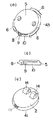
前述のように固定部5の前面板部44に凸部9を有したたわみ片10を設けると共に被固定部2の前面部に上記凸部9がはめ込まれる凹部11を設けてロック手段8が構成してあるのであるが、このロック手段8の一構成部位である凹部11としては図14に示すように貫通孔により構成してあってもよい。このように貫通孔により凹部11を構成した場合、図14(a)(b)に示す実施形態では、凹部11の表面側の周囲を内方に凹んだ半球面状凹み11aとしてある。そして、ロック状態では図14(b)のように該半球面状凹み11aの底に設けた凹部11を構成する貫通孔に凸部9が嵌挿してある。このように凹部11の表面側の周囲を内方に凹んだ半球面状凹み11aとすることで、ロックを解除する場合に、半球面状凹み11aに指を押し当てて指により凸部9を押してロック解除をすることができるものである。このようにすることで、ロック状態では指で押さないかぎり、被固定部2を回動してもロックがはずれにくい構造とすることができるものである。
【0027】
次に、図15に基づいて被固定部2の固定部5に対する回転方向の位置決めと取付け状態を保持するために被固定部2を固定部5に取付けた状態で設定以下の力では回転不能で且つ設定以上の力で回転可能とするロック手段8の他の実施形態につき説明する。図15に示す実施形態においては、固定部5の円筒部43の一部に凸部9を有するたわみ片10を設け、被固定部2の略円筒状をした周壁部41に凹部11を設けてロック手段8を構成してある。この実施形態においては、被固定部2の周壁部41を固定部5の円筒部43にはめ込んだはじめの状態では凸部9が被固定部2の周壁部41の内面に当たってたわみ片10がたわんでおり、このように凸部9が被固定部2の周壁部41の内面に当たった状態で被固定部2を回動すると、凸部9と凹部11とが対向し、凸部9がたわみ片10の弾性力により凹部11に嵌まりこんで周方向の位置決めがなされると共に周方向の回転を規制するためのロックがなされるのである。
【0028】
図16にはロック手段8の更に他の実施形態が示してあり、この実施形態においては、円筒部43の周方向に複数等分する位置に設けた各係止部6乃至周壁部41の周方向に複数等分する位置に設けた各被係止部7の対向面のいずれか一方に突起部50をいずれか他方に凹所51を設けてロック手段8が構成してある。図16に示す実施形態では3つの係止部6にそれぞれ突起部50を設け、3つの被係止部7にそれぞれ凹所51を設けてあり、係止部6と被係止部7とを係止した状態で各突起部50と各凹所51とが係止して周方向のロックがなされるものである。
【0029】
ここで、3つの突起部50は120°の開き角度を介して設けてあり、また、3つの凹所51は120°の開き角度を介して設けてあり、このため、係止部6と被係止部7を係止して突起部50を凹所51に係止できる位置は被固定部2を固定部5に対して取り付けた位置から更に、120°、240°回転した位置でも係止部6と被係止部7を係止して突起部50を凹所51に係止できることになり、合計3箇所でロックがなされように取付けることができるものである。同様にして係止部6、被係止部7の数、突起部50、凹所51の数によりロックできる位置の数が2箇所又は4箇所以上とすることもできるものである。このようにして固定部5に対する被固定部2の固定姿勢を周方向に複数の姿勢に選択できるものである。
【0030】
ところで、図4に示すように、照明器具本体3の前面部に複数個のLEDのような照明手段81からの光を拡散するためのレンズ部22が横方向に長く突出して形成してあるが、このレンズ部22の長手方向の延長にほぼ人の指1本程度の間隔を隔てて人体検知手段27が前方に凸状に突出して形成してあるので、照明器具本体3を携帯用の照明器具として手で持って使用する場合、レンズ部22の延長部分が握り部となり、レンズ部22を手で塞ぐことなく人体検知手段27を突出した部分を中心にして滑らないようにして確実に手で掴んで使用できるものである。
【0031】
なお、図1に示すように、室内の明暗を判断する手段(図示せず)のカバー26が照明手段81からの光を拡散するためのレンズ部22を設けた面と異なる面(実施形態では直角にずれている)に設けてあり、このことにより室内の明暗を判断する手段の感度域を照
明手段81の照射範囲から避けることができるものである。
【0032】
図17には本発明の他の実施形態が示してある。この実施形態においては、被固定部2を固定部5に対して回動して着脱する例につき説明したが、図17に示すように、壁や天井等の取付け面12に固定する固定部5に対して被固定部2をスライドにより着脱自在に取付けるようにしてもよい。すなわち、図17にはスライドにより着脱自在に取付ける一実施形態が示してあり、固定部5に設けた突片状の係止部6の背面側に被固定部2に設けた突片状の被係止部7がスライド自在に係止し、被固定部2のストッパ片70が固定部5の当たり部71に当たって支持されるようになっている。もちろんこの実施形態においても、図示を省略しているが被固定部2に照明器具本体3が回動自在に取付けられるものであり、被固定部2を固定部5から外した状態で、被固定部2を置き台として使用することができるものである。
【0033】
【発明の効果】
本発明の請求項1記載の発明にあっては、上述のように、内部に電源手段を収容した照明器具本体と、照明器具本体の背部から突出したアーム部と、アーム部と回動自在に軸支する軸受け部を前面側に設けた被固定部と、壁や天井等に固定されるものであって被固定部を着脱自在に取付ける固定部とを備えた照明装置において、被固定部を照明器具本体の置き台としてあるので、照明器具本体を壁や天井等の取付け面に取付けて使用できるのはもちろん、固定部から被固定部を外した状態では置き台を兼用する被固定部を床や机や家具やその他の台の上に安定して載せて安定した姿勢で使用できるものである。しかも、照明器具本体を被固定部に回動部により回動自在に取付けてあるので、照明器具本体を回動することで、照明エリアを拡大できるものであり、また照明方向を変えることができるものである。また、被固定部の前面に設けた軸受け部又は照明器具本体の背部から背方に突出したアーム部のいずれかに押圧手段により押圧される軸用突部を設けると共にいずれか他方に軸用突部が回動自在に嵌まり込むはまり込み部を設けて軸用突部とはまり込み部とで回動部を構成し、照明器具本体の前面に対して直交する方向で照明器具本体の側面を2分割する分割線を設定し、照明器具本体を回動して分割線が被固定部の前面と略平行となった状態で該分割線と被固定部の前面との間に回動部の回動中心が位置するように設定してあるので、照明器具本体を回動した場合における取付け面からの突出長さを短くできて、照明器具が邪魔になりにくく、また、突出長さが長いことによる不快感がないものである。更に、軸受け部又はアーム部のいずれかに押圧手段により押圧される軸用突部を設けると共にいずれか他方に軸用突部が回動自在に嵌まり込むはまり込み部を設けてあるので、アームを任意の回動角度で保持することができて角度調整が簡単にできると共に、アームを軸受け部から取り外したり、アームを軸受け部に取付けたりするのが簡単にでき、また、アームを軸受け部から取り外した場合には照明器具本体を携帯用の懐中電灯の代わりとして使用することができるものである。
【0034】
また、請求項2記載の発明にあっては、上記請求項1記載の発明の効果に加えて、固定部に係止部を設け、被固定部に係止部に係止される被係止部を設けてあるので、固定部に対して被固定部を取り付けるに当たり、係止という簡単な取付けにより取付けることができるものであり、被固定部の着脱が容易にできるものである。
【0035】
また、請求項3記載の発明にあっては、上記請求項2記載の発明の効果に加えて、固定部が所定の厚みを有し、該固定部の側面に係止部を設け、被固定部に被係止部を設け、被固定部の固定部に対する回転により被係止部を係止部に係止するように構成してあるので、係止部と被係止部との係止が回転という簡単な手段によりできるものであり、また、被固定部に地震等の振動や人間による衝撃が作用しても、被固定部に作用する上記外力は直線方向の外力が一般的であり、このため、係止部と被係止部との係止が外れにくいものである。
【0036】
また、請求項4記載の発明にあっては、請求項3記載の発明の効果に加えて、被固定部を固定部に取付けた状態で設定以下の力では回転不能で且つ設定以上の力で回転可能とするロック手段を設け、該ロック手段が固定部に設けられる凸部を有したたわみ片と、被固定部に設けられた凸部がはめ込まれる凹部とで構成してあるので、地震等の振動や人間による衝撃によりロックが外れにくい構造とすることができるものである。
【0037】
また、請求項5記載の発明にあっては、請求項4記載の発明の効果に加えて、たわみ片
が被固定部の回転方向に対して垂直方向に撓むように構成してあるので、簡単な構成で、ロックが外れにくい構造にできるものである。また、請求項6記載の発明にあっては、請求項1記載の発明の効果に加えて、固定部に被固定部を取付けた状態で、壁、天井等の取付け面に被固定部が接触しないように設定してあるので、被固定部の着脱に当たって取付け面に傷を与えず、また、着脱時に被固定部と取付け面とが摺接することによる不快な音が発生しないものである。
【0038】
また、請求項7記載の発明にあっては、上記請求項4記載の発明の効果に加えて、凹部を貫通孔とし、凹部の周囲をたわみ片の凸部が凹部より突出するように内方に半球面状に凹んだ半球面状凹みとしてあるので、外したい場合には半球面状凹みとなった凹部に指を入れて凸部を押すことで凸部を凹部から脱離させることができるものであり、また、指で押さないかぎり凸部が凹部から脱離しない構造のものとすることができて、地震や人間が加える衝撃で凸部が凹部から外れない構造とすることもできるものである。
【図面の簡単な説明】
【図1】 本発明の一実施形態の斜視図である。
【図2】 (a)(b)は同上の側面図及び回動を示す側面図である。
【図3】 同上の断面図である。
【図4】 照明器具本体部分の断面図である。
【図5】 (a)は本発明の回動部を示す正面図であり、(b)は同上の断面図であり、(c)は同上の拡大断面図であり、(d)はアーム部の斜視図であり、(e)は軸用突部の斜視図である。
【図6】 同上の壁面等の取付け面に取付けた場合の断面図である。
【図7】 (a)は同上に用いる固定部の斜視図であり、(b)は被固定部の背面側から見た斜視図である。
【図8】 同上の壁面に取付けた場合の側面図である。
【図9】 (a)は同上の照明器具本体を回動した場合の取付け面からの突出長さが短い例を示す説明図であり、(b)は照明器具本体を回動した場合の取付け面からの突出長さが長い例を示す説明図である。
【図10】 (a)(b)(c)は同上の固定部に被固定部を取付ける順序を示す説明図である。
【図11】 (a)(b)は同上の固定部に被固定部を取付ける途中の状態を示す側面側から見た断面図及び下面側から見た一部破断した断面図である。
【図12】 (a)(b)は同上の固定部に被固定部を取付けた状態を示す側面側から見た断面図及び下面側から見た一部破断した断面図である。
【図13】 (a)は同上の同上の凸部と凹部との係止部分を示す断面図であり、(b)は同上の拡大断面図であり、(c)は凸部の側面の角度と凹部の内壁面の角度を示す説明図である。
【図14】 (a)は本発明の他の実施形態の凹部の正面図であリ、(b)は凹部に凸部を係止した状態の断面図である。
【図15】 (a)は本発明の他の実施形態の凸部を示す斜視図であり、(b)は同上の側面図であり、(c)は凹部を示す斜視図である。
【図16】 (a)は本発明の他の実施形態の凸部を示す斜視図であり、(b)は同上の取付け状態の断面図である。
【図17】 (a)は本発明の他の実施形態の回動部を示す分解斜視図であり、(b)は取付け状態の一部破断した側面図である。
【符号の説明】
1 電源手段
2 被固定部
3 照明器具本体
4 置き台
5 固定部
6 係止部
7 被係止部
8 ロック手段
9 凸部
10 たわみ片
11 凹部
11a 半球状凹み
12 取付け面
13 アーム部
14 軸受け部
15 回動部
16 軸用突部
17 はまり込み部
[0001]
BACKGROUND OF THE INVENTION
  The present invention relates to a lighting device that can illuminate the surroundings even in a place without an AC 100V outlet.
[0002]
[Prior art]
  2. Description of the Related Art In recent years, lighting devices have been provided that can illuminate the surroundings using a power source such as a dry battery, a rechargeable battery, or a battery as a power source. These lighting devices are called sensor lights that automatically turn on when the surroundings become dark at night or turn on only when a person comes nearby. These lighting devices are installed in corridors, passages, entrances, storerooms, etc. where AC100V outlets are not arranged, and should be installed in places where lighting cannot be performed with lighting devices installed in the house in advance. There are many.
[0003]
[Problems to be solved by the invention]
  This type of battery-powered lighting device has the advantage that it can be used anywhere. However, this type of battery-powered lighting device is attached by a hook type or a completely fixed type by screwing, etc. In the hook type, the body of the luminaire falls due to a position touched by a body such as a hand or an impact such as an earthquake. There is a problem of injuries, and there is no such problem as in the fully fixed type, but there is a problem that once it is attached, it is difficult to remove or troublesome to remove. Furthermore, although the above-mentioned hook type can be removed, if it is removed and placed on the floor, desk, furniture, or other table, the installation is unstable and cannot be used in the set posture. There is a problem.
[0004]
  The present invention was invented in view of the problems of the above-described conventional example, and can be easily attached and detached, and when removed, it can be stably placed on a floor, desk, furniture, or other table. It can be used in a set posture, and when attached to a fixed part attached to a mounting surface such as a wall or ceiling, it can be attached and detached so that it will not easily come off even if there is an impact from a person, earthquake, etc. It is an object of the present invention to provide an illuminating device capable of shortening a protruding length from a mounting surface such as a wall or a ceiling when a rotatable lighting fixture is rotated in a state where a fixed portion is attached. .
[0005]
[Means for Solving the Problems]
  In order to solve the above problems, the lighting device of the present invention accommodates the power supply means 1 inside.The luminaire main body 3, the arm portion 13 protruding from the back of the luminaire main body 3, and the fixed portion 2 provided on the front side with a bearing portion 14 that pivotally supports the arm portion 13.In a lighting device provided with a fixing part 5 that is fixed to a wall, a ceiling, etc., and to which the fixed part 2 is detachably attached,Bearing part 14Alternatively, either one of the arm portions 13 is provided with a shaft projection 16 that is pressed by the pressing means, and the other portion is provided with a fitting portion 17 into which the shaft projection 16 is rotatably fitted.The shaft protrusion 16 and the fitting part 17 constitute the rotating part 15,A dividing line M that divides the side surface of the luminaire main body 3 into two in a direction orthogonal to the front surface of the luminaire main body 3 is set, and the luminaire main body 3 is rotated so that the dividing line M is connected to the front surface of the fixed portion 2. The center of rotation of the rotating portion 15 is set between the dividing line M and the front surface of the fixed portion 2 in a substantially parallel state, and the fixed portion 2 is placed on the lighting fixture body 3. It is characterized by comprising as a stand 4. By adopting such a configuration, it can be used in a state where the fixed portion 2 provided on the back surface portion of the lighting fixture body 3 is attached to the fixing portion 5 attached to the attachment surface 12 such as a wall or a ceiling. When the fixture body 3 is used in a detached state, the lighting fixture body 3 can be stabilized by placing the fixed portion 2 that also serves as the stand 4 on the floor, desk, furniture, or other table. It can be used in the set posture. In addition, the illumination angle can be set in a wide range by rotating the lighting fixture body 3 around the rotation unit 15. Also,Either one of the bearing 14 provided on the front surface of the fixed part 2 or the arm 13 protruding backward from the back of the luminaire main body 3 is provided with a shaft protrusion 16 that is pressed by the pressing means and on the other. The shaft projection 16 is provided with a fitting portion 17 into which the shaft projection 16 is rotatably fitted, and the shaft projection 16 and the fitting portion 17 constitute the rotation portion 15.A dividing line M that divides the side surface of the luminaire main body 3 into two in a direction orthogonal to the front surface of the luminaire main body 3 is set, and the luminaire main body 3 is rotated so that the dividing line is substantially the same as the front surface of the fixed portion 2. Since the rotation center of the rotation unit 15 is set between the dividing line M and the front surface of the fixed portion 2 in a parallel state, the lighting fixture body 3 is rotated. The protrusion length from the front surface of the fixed part 5 can be shortened. Furthermore, a shaft protrusion 16 that is pressed by the pressing means is provided on either the bearing portion 14 or the arm portion 13, and a fitting portion 17 in which the shaft protrusion 16 is rotatably fitted is provided on either one of them.Thus, the pivoting portion 15 is constituted by the shaft projection 16 and the fitting portion 17.Therefore, the lighting fixture body 3 can be fixed at an arbitrary rotation angle while being freely rotatable, and the lighting fixture body 3 can be detached from the fixed portion 2.
[0006]
  It is also preferable to provide the locking portion 6 in the fixing portion 5 and the locked portion 7 to be locked to the locking portion 6 in the fixed portion 2. With such a configuration, the fixed portion 2 can be easily attached to the fixing portion 6 by the locking of the locking portion 6 and the locked portion 7 or can be removed by releasing the locking. Is.
[0007]
  In addition, the fixing portion 5 has a predetermined thickness, the locking portion 6 is provided on the side surface of the fixing portion 5, the locked portion 7 is provided in the fixed portion 2, and the rotation of the fixed portion 2 relative to the fixing portion 5 is performed. It is also preferable that the locked portion 7 is configured to be locked to the locking portion 6. With such a configuration, it can be locked or unlocked by a simple means of rotation, and when an external force is applied to a lighting fixture, a linear external force is usually applied. For this reason, even if an external force is applied, the fixed portion is difficult to rotate, and the external force is difficult to release the locking carelessly.
[0008]
  In addition, a lock unit 8 is provided that allows the fixed portion 2 to be attached to the fixed portion 5 and cannot be rotated with a force less than a set value but can be rotated with a force greater than the set value. The lock unit 8 is provided on the fixed portion 5. It is also preferable that the flexure piece 10 having the convex portion 9 and the concave portion 11 into which the convex portion 9 provided on the fixed portion 2 is fitted are preferable. By adopting such a configuration, the locking means 8 having a simple configuration can prevent the locking from being released.
[0009]
  It is also preferable that the flexible piece 10 is configured to bend in a direction perpendicular to the rotation direction of the fixed portion 2. With such a configuration, the lock means 8 having a simple structure can be configured.
[0010]
  It is also preferable that the fixed portion 2 is set so as not to contact the mounting surface 12 such as a wall or a ceiling in a state where the fixed portion 2 is attached to the fixing portion 5. By adopting such a configuration, it is possible to install without damaging the mounting surface 12 when the fixed portion 2 is attached to the fixing portion 5.It is.
[0011]
  It is also preferable that the concave portion 11 is a through-hole, and the concave portion 11 is a hemispherical recess 11 a that is recessed inwardly in a semispherical shape so that the convex portion 9 of the flexible piece 10 protrudes from the concave portion 11. By adopting such a configuration, it is possible to release the engagement between the convex portion 9 and the concave portion 11 by putting a finger into the hemispherical recess 11a and pushing the convex portion 9, and releasing the lock to fix the fixed portion. Easy to remove the fixed part 2 from 5become.
[0012]
DETAILED DESCRIPTION OF THE INVENTION
  Embodiments of the present invention will be described below with reference to the accompanying drawings. As shown in FIGS. 1 to 3, a fixed portion 2 is attached to the back of the luminaire main body 3. The luminaire main body 3 has an outer shell formed of a front case 20 and a rear case 21, and lighting means 81 is provided in the front case 20, and light from the lighting means 81 is applied to the front portion of the front case 20. A lens portion 22 for diffusing is attached by adhesion or welding. For example, the illumination unit 81 includes a plurality of LEDs.FIG.Are arranged in a straight line as shown in FIG. On the outer surface of the front case 20, there are further lighting means 81 on, off, automatic, etc.Operating means (not shown)Cover 24, andMeans (not shown) for judging indoor lightingThe cover 26 is attached by fitting. In addition, a circuit unit 28 including a human body detection means 27 is built in the front case 20, the human body detection means 27 is exposed from the hole of the front case 20, and the power supply means 1 such as a battery is further provided in the front case 20. A holder 29 for holding the battery means 1 is provided, and the holder 29 is provided with a contact portion 30 for electrical connection with the battery means 1.
[0013]
  A rear case 21 is attached to the front case 20 with screws 31. A power cover 32 is detachably attached to the opening of the rear case 21 by a hook portion 33 and a fixing rib 33a. The power supply means 1 is replaced by removing the power cover 32. Rear case 21
An arm portion 13 protrudes toward the back side, and the arm portion 13 is rotatably attached to a bearing portion 14 provided on the front surface portion of the fixed portion 2.
[0014]
  As shown in FIG. 5, a pair of protrusions that serve as bearing portions 14 project from the front portion of the fixed portion 2, and the arm portion 13 can turn freely on the bearing portion 14.It is installed.
[0015]
  That is, as shown in FIG. 5, a shaft projection 16 that is pressed by the pressing means 65 is provided on either the bearing portion 14 or the arm portion 13, and the shaft projection 16 is rotatably fitted on one of the other. The turning portion 15 is configured by providing a fitting portion 17 (in FIG. 5, a shaft protrusion 16 that is pressed by the pressing means 65 is provided on the bearing portion 16 side, and both side surfaces of the arm portion 13 are provided. Are provided with a recessed fitting portion 17). In FIG. 5, the bearing portion 16 has a hemispherical shape and is provided with a flange portion 16 a at the end, and the hemispherical portion of the bearing portion 16 is fitted into a hole provided in the inner wall surface portion of the bearing portion 14. The shaft protrusion 16 is pressed in a direction protruding from a hole provided in the inner wall surface of the bearing portion 14 by a pressing means 65 constituted by a coil spring built in the bearing portion 14.
[0016]
  Here, due to the presence of the flange portion 16a, the shaft projection 16 is prevented from falling off from a hole provided in the inner wall surface portion. On the other hand, both side surface portions of the arm portion 13 are recessed to form a fitting portion 17, and the diameter of the inner surface side of the depression constituting the fitting portion 17 is as shown in FIG. The diameter of the projection 16 for the shaft is smaller than the diameter on the outer surface side of the hemispherical portion. Therefore, as shown in FIG. The outer surface of the projection 16 is elastically contacted in an annular line, and the tip of the shaft projection 16 is fitted into the fitting portion 17 so that it is difficult to come out. In this way, the shaft projection 16 is elastically pressed against the fitting portion 17 and pivotally supported, so that the arm portion 13 can be maintained at an arbitrary rotation angle when it is rotated. Further, when the arm portion 13 is pulled with a large force, the arm portion 13 can be detached from the bearing portion 14, and the lighting fixture body 3 itself can be held by hand and used as a portable lighting fixture.
[0017]
  The fixed part 2 can be attached to and detached from a fixing part 5 attached to an attachment surface 12 such as a ceiling or a wall as will be described later, and the luminaire main body 3 is placed on a floor, a desk, furniture, or another mounting surface such as a table. The rear surface (that is, the lower surface) of the fixed portion 2 serves as a placement surface portion 2a so that it can also be used as the placement table 4 when placed on the surface 40. 1, 2, and 3, the placing surface portion 2 a of the rear surface (that is, the lower surface) of the fixed portion 2 that is the placing table 4 is placed on a placing surface 40 such as a floor, desk, furniture, or other table. This shows an example of using it.
[0018]
  The luminaire main body 3 rotates with respect to the fixed portion 2 around the rotating portion 15 as shown by the arrow in FIG. 2B to change the angle of the illumination area and the luminaire main body 3 with respect to the fixed portion 2. Can be done. The fixed part 2 isFIG. 7 (b)As shown in the figure, a substantially cylindrical peripheral wall 41 is projected from the front to the back, an annular rib 42 is projected from the center of the back of the front, and a recess is formed in the front. 11 is formed. In addition, the locked portion 7 protrudes inwardly at a position that is divided into a plurality of equal parts in the circumferential direction (three equal parts in the embodiment) at the rear edge of the substantially cylindrical peripheral wall part 41. .
[0019]
  The fixing portion 5 which is a member for mounting on the mounting surface 12 such as a wall or ceiling isFIG. 7 (a)As shown in FIG. 4, a front plate 44 is provided at the front end of the cylindrical portion 43, and a screw is inserted from a hole 45 provided in the front plate 44 to be attached to a mounting surface 12 such as a wall or a ceiling. . On the outer peripheral portion of the cylindrical portion 43 of the fixed portion 5, a locking portion 6 protrudes outward at a position where it is equally divided into a plurality of portions (3 in the embodiment) in the circumferential direction.
[0020]
  AndFIG. 10 (a)As shown in Fig. 4, the lighting fixture main body 3 with the fixed portion 2 attached to the back portion is adjacent to the fixing portion 5 attached to the mounting surface 12 such as a wall or ceiling, and is adjacent to the locking portion. The peripheral wall portion 41 of the fixed portion 2 that is cylindrical from the front so that the locked portion 7 is positioned between the six portions 6 is replaced with the cylindrical portion 43 of the fixing portion 5.FIG. 10 (b)In this state,FIG. 10 (b)Rotate the fixed part 2 with respect to the fixing part 5 as indicated by the arrowFIG. 10 (c)This is what you want to doFIG. 10 (c)In this state, the locked portion 7 is locked to the locking portion 6, and the fixed portion 2 is attached to the fixed portion 5.
[0021]
  In this way, the fixed part 2 is attached to the fixed part 5 by rotation.
In the present invention, positioning in the rotational direction of the fixed part 2 with respect to the fixed part 5, confirmation of positioning by a click feeling, and setting of the fixed part 2 attached to the fixed part 5 in order to maintain the attached state Locking means 8 is provided which cannot be rotated by force and can be rotated by a force greater than a set value.
[0022]
  FIG.1 shows an example of the locking means 8. In this embodiment, the front plate portion 44 of the fixing portion 5 is provided with a flexible piece 10 having the convex portion 9, and the convex portion is provided on the front portion of the fixed portion 2. The locking means 8 is configured by providing a recess 11 into which 9 is fitted. And above10 (a), (b), (c)When the locked portion 7 of the fixed portion 2 is locked and attached to the locking portion 6 of the fixed portion 5 in this order,FIG. 10 (b)In the state ofFIG.As shown in FIG. 4, the flexible piece 10 is bent with the convex portion 9 abutting against the back surface of the front portion of the fixed portion 2, and the fixed portion with the convex portion 9 hitting the back surface of the front portion of the fixed portion 2 as described above 2FIG. 10 (c)When it is rotated to the state of, the convex portion 9 and the concave portion 11 face each other,FIG.As shown in FIG. 4, the convex portion 9 is fitted into the concave portion 11 by the elastic force of the flexure piece 10 so that the circumferential positioning by the click feeling can be confirmed and the circumferential rotation is performed in the state where the circumferential positioning is performed in this way. A lock is made to regulate this.
[0023]
  Here, the bending piece 10 is the rotational direction of the fixed part 2 (FIG. 13 (a)In the direction perpendicular to the arrow a)FIG. 13 (a)The direction of the arrow b)FIG. 13 (c)As shown in FIG. 4, when the angle formed between the back surface of the front surface portion of the fixed portion 2 and the side surface of the concave portion 11 is α, the angle formed between the flexure piece 10 of the convex portion 9 is α + β, and α <α + β. It is set. Moreover, the corner part which the front end surface and side surface of the convex part 9 make is chamfered in the round shape, and by these,FIG. 13 (b)In the case where the lock is released by applying a force in the H direction, the structure can be made such that the lock can be released in terms of dynamics. That is, when α = (α + β), the lock cannot be released, but the lock can be released by setting α <α + β. Then, by adjusting the angle of β in the range of more than 0 ° to less than 180, the unlocking force can be easily used, or an appropriate unlocking force can be set according to users such as men and women of all ages. Further, the corner portion formed by the tip surface and the side surface of the convex portion 9 is chamfered into a rounded shape so that unlocking without a sense of incongruity can be performed.
[0024]
  With the fixed part 2 attached to the fixing part 5 attached to the attachment surface 12 such as a wall or ceiling,FIG.As shown in FIG. 2, the rear end portion of the fixed portion 2 does not come into contact with the mounting surface 12 such as a wall or a ceiling. Here, the annular rib 42 formed on the back surface of the fixed portion 2 is in contact with the front plate portion 44 of the fixed portion 5, whereby the fixed portion 2 moves to the fixed portion 5 side and is fixed. The rear end portion 2 does not contact the mounting surface 12 such as a wall or a ceiling, and the mounting surface 12 is not damaged by the fixed portion 2 not contacting the mounting surface 12. Further, when the annular rib 42 formed on the back surface of the fixed portion 2 is in contact with the front plate portion 44 of the fixed portion 5, the fixed portion 2 is put on the fixed portion 5 and is rotated and attached. The contact surface is reduced, and attachment / detachment operation by rotation is facilitated.
[0025]
  As described above, the arm portion 13 protrudes from the back portion of the luminaire main body 3 toward the back, and the arm portion 13 can freely rotate on the bearing portion 14 provided on the front side of the fixed portion 2 as described above. Although the rotation part 15 is comprised by pivotally supporting to, when the dividing line M which divides the side surface of the lighting fixture main body 3 into two in the direction orthogonal to the front surface of the lighting fixture main body 3 is set,FIG. 9 (a)As shown in FIG. 4, the rotating unit is rotated between the dividing line M and the front surface of the fixed part 2 in a state where the dividing line M is substantially parallel to the front surface of the fixed part 2. It is set so that 15 rotation centers are located. That is, when pivoting the arm portion 13 on the bearing portion 14,FIG. 9 (b)As described above, when the rotation center of the arm portion 13 and the bearing portion 14 is positioned on the extension line of the dividing line M, the mounting surface 12 such as a wall or a ceiling when the lighting fixture body 3 is rotated by an angle γ. L to the front end of the luminaire body 32 IfFIG. 9 (a)The rotating unit 15 is rotated between the dividing line M and the front surface of the fixed part 2 in a state where the lighting fixture body 3 is rotated as described above and the dividing line M is substantially parallel to the front surface of the fixed part 2. If the lighting fixture body 3 is rotated at an angle γ, the length from the mounting surface 12 such as a wall or ceiling to the front end of the lighting fixture body 3 is set to a length L1. L1 <L2 And the mounting surface 1 when the lighting fixture body 3 is rotated.
The projection length from 2 can be shortened, and the rotation angle can be taken over a wide range with a small projection length, and the illumination angle can be taken over a wide range.
[0026]
  As described above, the locking plate 8 is configured by providing the flexible plate 10 having the convex portion 9 on the front plate portion 44 of the fixing portion 5 and providing the concave portion 11 into which the convex portion 9 is fitted on the front portion of the fixed portion 2. However, as the concave portion 11 which is one component part of the locking means 8,FIG.As shown in FIG. 4, it may be constituted by a through hole. When the concave portion 11 is configured by the through hole in this way,14 (a) and 14 (b)In the embodiment shown in FIG. 1, the concave portion 11 has a hemispherical recess 11a in which the periphery on the surface side is recessed inward. And in the locked stateFIG. 14 (b)As described above, the convex portion 9 is inserted into the through-hole constituting the concave portion 11 provided at the bottom of the hemispherical concave portion 11a. In this way, by forming the hemispherical recess 11a that is recessed inward around the surface side of the recess 11, when releasing the lock, the finger is pressed against the hemispherical recess 11a and the convex 9 is moved by the finger. It can be unlocked by pressing. By doing so, the lock can be prevented from being released even if the fixed portion 2 is rotated unless it is pushed with a finger in the locked state.
[0027]
  next,FIG.In order to maintain the positioning and the mounting state of the fixed portion 2 with respect to the fixed portion 5 based on the above, it is impossible to rotate with the force below the setting while the fixed portion 2 is attached to the fixed portion 5 and the force beyond the setting Another embodiment of the lock means 8 that can be rotated will be described.FIG.In the embodiment shown in FIG. 3, the flexible piece 10 having the convex portion 9 is provided in a part of the cylindrical portion 43 of the fixing portion 5, and the concave portion 11 is provided in the substantially cylindrical peripheral wall portion 41 of the fixed portion 2 to provide locking means. 8 is configured. In this embodiment, in the first state where the peripheral wall portion 41 of the fixed portion 2 is fitted into the cylindrical portion 43 of the fixed portion 5, the convex portion 9 hits the inner surface of the peripheral wall portion 41 of the fixed portion 2 and the flexible piece 10 is bent. Thus, when the fixed portion 2 is rotated in a state where the convex portion 9 is in contact with the inner surface of the peripheral wall portion 41 of the fixed portion 2, the convex portion 9 and the concave portion 11 face each other, and the convex portion 9 is a flexible piece. The elastic force of 10 fits into the recess 11 for positioning in the circumferential direction and locking for restricting circumferential rotation.
[0028]
  FIG.FIG. 4 shows still another embodiment of the lock means 8. In this embodiment, in the circumferential direction of each of the locking portions 6 to the circumferential wall portions 41 provided at a position equally divided in the circumferential direction of the cylindrical portion 43. The locking means 8 is configured by providing a protrusion 50 on one of the opposed surfaces of each of the locked portions 7 provided at a position where the portions are equally divided and a recess 51 on the other.FIG.In the embodiment shown in FIG. 3, the protrusions 50 are provided on the three locking portions 6, and the recesses 51 are provided on the three locked portions 7, respectively, so that the locking portions 6 and the locked portions 7 are locked. In this state, the protrusions 50 and the recesses 51 are locked to lock in the circumferential direction.
[0029]
  Here, the three protrusions 50 are provided through an opening angle of 120 °, and the three recesses 51 are provided through an opening angle of 120 °. The position where the locking portion 7 can be locked and the protruding portion 50 can be locked in the recess 51 is also locked at a position rotated by 120 ° or 240 ° from the position where the fixed portion 2 is attached to the fixing portion 5. The protrusion 6 can be locked in the recess 51 by locking the portion 6 and the locked portion 7, and can be attached so as to be locked at a total of three locations. Similarly, the number of positions that can be locked can be two or four or more depending on the number of the locking portions 6 and the locked portions 7, the number of the protrusions 50, and the number of the recesses 51. Thus, the fixed posture of the fixed portion 2 with respect to the fixed portion 5 can be selected from a plurality of postures in the circumferential direction.Is.
[0030]
  By the way, as shown in FIG. 4, although the lens part 22 for diffusing the light from the illumination means 81 like several LED is protruded long in the front part of the lighting fixture main body 3, it protrudes in the horizontal direction. Since the human body detecting means 27 is formed so as to protrude forward in the longitudinal direction of the lens portion 22 with an interval of about one person's finger, the luminaire main body 3 is portablely illuminated. When used as a tool by hand, the extended portion of the lens portion 22 becomes a grip portion, and the hand is surely prevented from slipping around the protruding portion of the human body detecting means 27 without blocking the lens portion 22 with a hand. It can be grabbed with and used.
[0031]
  As shown in FIG.Means (not shown) for judging indoor lightingThe cover 26 is provided on a surface different from the surface on which the lens portion 22 for diffusing the light from the illumination means 81 is provided (in the embodiment, it is shifted at a right angle).Means to judge indoor lightingThe sensitivity range of
This can be avoided from the irradiation range of the bright means 81.
[0032]
  FIG.Shows another embodiment of the present invention. In this embodiment, although the fixed part 2 was demonstrated about the example which rotates with respect to the fixing | fixed part 5, and attaches / detaches,FIG.As shown, the fixed portion 2 may be detachably attached to the fixing portion 5 fixed to the attachment surface 12 such as a wall or a ceiling by sliding. That is,FIG.1 shows an embodiment in which it is detachably attached by sliding, and a protruding piece-like locked portion 7 provided on the fixed portion 2 on the back side of the protruding piece-like locking portion 6 provided on the fixed portion 5. The stopper piece 70 of the to-be-fixed part 2 hits the contact part 71 of the fixing | fixed part 5, and is supported. Of course, in this embodiment as well, although not shown, the luminaire main body 3 is pivotally attached to the fixed portion 2, and the fixed portion 2 is fixed with the fixed portion 2 removed from the fixing portion 5. The part 2 can be used as a stand.
[0033]
【The invention's effect】
  In the first aspect of the present invention, as described above, the power supply means is accommodated inside.A lighting fixture body, an arm portion protruding from the back of the lighting fixture body, and a fixed portion provided on the front side with a bearing portion pivotally supported by the arm portion.In a lighting device that is fixed to a wall, a ceiling, or the like and includes a fixing portion that detachably attaches the fixed portion, the fixed portion is used as a mounting base for the lighting fixture main body. It can be used by mounting on a mounting surface such as a ceiling or ceiling, and when the fixed part is removed from the fixed part, the fixed part that also serves as a pedestal can be stably placed on the floor, desk, furniture, or other table. It can be used with a stable posture. In addition, since the luminaire main body is rotatably attached to the fixed portion by the rotating portion, the illumination area can be expanded by rotating the luminaire main body, and the illumination direction can be changed. Is. Also,Either a bearing provided on the front surface of the fixed part or an arm projecting backward from the back of the luminaire main body is provided with a shaft protrusion pressed by the pressing means, and a shaft protrusion is provided on the other side. A fitting part is provided that fits in a freely rotatable manner, and a pivoting part is constituted by the projecting part for the shaft and the fitting part,A dividing line that divides the side surface of the luminaire main body into two in a direction perpendicular to the front surface of the luminaire main body is set, and the luminaire main body is rotated so that the dividing line is substantially parallel to the front surface of the fixed portion. Since the rotation center of the rotating part is set between the dividing line and the front surface of the fixed part, the projection length from the mounting surface when the lighting fixture body is rotated is shortened. In addition, the lighting apparatus is not easily disturbed, and there is no discomfort due to the long protrusion length. Furthermore, since either the bearing portion or the arm portion is provided with a shaft projection pressed by the pressing means, and the other side is provided with a fitting portion into which the shaft projection is rotatably fitted. Can be held at an arbitrary rotation angle and the angle can be easily adjusted, and the arm can be easily detached from the bearing portion and attached to the bearing portion. The arm can be removed from the bearing portion. When removed, the luminaire main body can be used as a substitute for a portable flashlight.
[0034]
  In addition, in the invention according to claim 2, in addition to the effect of the invention according to claim 1, a locked portion is provided in the fixed portion, and the locked portion is locked in the locked portion. Since the portion is provided, when the fixed portion is attached to the fixed portion, the fixed portion can be attached by simple attachment, and the fixed portion can be easily attached and detached.
[0035]
  According to the invention of claim 3, in addition to the effect of the invention of claim 2, the fixing portion has a predetermined thickness, and a locking portion is provided on a side surface of the fixing portion to fix the fixing portion. Since the portion to be locked is provided and the locked portion is locked to the locking portion by rotation of the fixed portion with respect to the fixing portion, the locking between the locking portion and the locked portion is performed. However, even if vibration such as an earthquake or an impact by a human acts on the fixed part, the external force acting on the fixed part is generally a linear external force. For this reason, the locking between the locking portion and the locked portion is difficult to release.
[0036]
  Further, in the invention described in claim 4, in addition to the effect of the invention described in claim 3, in a state where the fixed portion is attached to the fixed portion, it cannot be rotated with a force less than the setting and with a force higher than the setting. Since there is provided a locking means for enabling rotation, the locking means is composed of a flexible piece having a convex part provided on the fixed part and a concave part into which the convex part provided on the fixed part is fitted, so that an earthquake or the like It is possible to make a structure in which the lock is difficult to be released due to vibration of a person or an impact by a human.
[0037]
  Further, in the invention described in claim 5, in addition to the effect of the invention described in claim 4, the flexible piece
Since it is configured to bend in a direction perpendicular to the rotation direction of the fixed portion, the lock can be easily removed with a simple configuration. Further, in the invention described in claim 6, in addition to the effect of the invention described in claim 1, in a state where the fixed part is attached to the fixed part, the fixed part comes into contact with the mounting surface such as a wall or a ceiling. Therefore, the attachment surface is not damaged when attaching and detaching the fixed portion, and unpleasant sound due to the sliding contact between the fixed portion and the attachment surface during attachment and detachment is not generated.
[0038]
  In the invention according to claim 7, the above-mentionedIn addition to the effect of the invention described in claim 4, since the concave portion is a through-hole, and the convex portion of the flexible piece protrudes from the concave portion around the concave portion, it is a hemispherical concave portion that is recessed inwardly into a hemispherical shape. If you want to remove it, you can remove the convex part from the concave part by putting your finger in the concave part that is a hemispherical concave part and pressing the convex part. It can be of a structure that does not detach from the recess, and can also have a structure in which the projection does not come off from the recess due to an earthquake or an impact applied by a human.
[Brief description of the drawings]
FIG. 1 is a perspective view of an embodiment of the present invention.
FIGS. 2A and 2B are a side view and a side view showing rotation, respectively.
FIG. 3 is a cross-sectional view of the above.
FIG. 4 is a cross-sectional view of a luminaire main body portion.
[Figure 5](A) is a front view which shows the rotation part of this invention, (b) is sectional drawing same as the above, (c) is an expanded sectional view same as the above, (d) is a perspective view of an arm part. (E) is a perspective view of the projection for shafts.
[Fig. 6]It is sectional drawing at the time of attaching to attachment surfaces, such as a wall surface same as the above.
[Fig. 7](A) is the perspective view of the fixing | fixed part used for the same as the above, (b) is the perspective view seen from the back side of the to-be-fixed part.
[Fig. 8]It is a side view at the time of attaching to the wall surface same as the above.
FIG. 9(A) is explanatory drawing which shows the example from which the protrusion length from the attachment surface at the time of rotating a lighting fixture main body same as the above is short, (b) is the protrusion from the attachment surface at the time of rotating a lighting fixture main body. It is explanatory drawing which shows an example with long length.
FIG. 10(A) (b) (c) is explanatory drawing which shows the order which attaches a to-be-fixed part to the fixing | fixed part same as the above.
FIG. 11(A) (b) is sectional drawing seen from the side surface which shows the state in the middle of attaching a to-be-fixed part to the fixing | fixed part same as the above, and sectional drawing seen partially from the lower surface side.
FIG.(A) (b) is sectional drawing seen from the side surface which shows the state which attached the to-be-fixed part to the fixing | fixed part same as the above, and sectional drawing partially broken seen from the lower surface side.
FIG. 13(A) is sectional drawing which shows the latching | locking part of a convex part same as the above, and a recessed part, (b) is an expanded sectional view same as the above, (c) is the angle of the side surface of a convex part, and inside of a recessed part It is explanatory drawing which shows the angle of a wall surface.
FIG. 14(A) is a front view of the recessed part of other embodiment of this invention, (b) is sectional drawing of the state which latched the convex part to the recessed part.
FIG. 15(A) is a perspective view which shows the convex part of other embodiment of this invention, (b) is a side view same as the above, (c) is a perspective view which shows a recessed part.
FIG. 16(A) is a perspective view which shows the convex part of other embodiment of this invention, (b) is sectional drawing of the attachment state same as the above.
FIG. 17(A) is a disassembled perspective view which shows the rotation part of other embodiment of this invention, (b) is the partially broken side view of an attachment state.
[Explanation of symbols]
1 Power supply means
2 Fixed part
3 lighting equipment
4 table
5 fixed part
6 Locking part
7 Locked part
8 Locking means
9 Convex
10 Deflection pieces
11 recess
11a Hemispherical dent
12 Mounting surface
13 Arm
14 Bearing part
15 Rotating part
16 Shaft protrusion
17 Inset part

Claims (7)

内部に電源手段を収容した照明器具本体と、照明器具本体の背部から突出したアーム部と、アーム部と回動自在に軸支する軸受け部を前面側に設けた被固定部と、壁や天井等に固定されるものであって被固定部を着脱自在に取付ける固定部とを備えた照明装置において、軸受け部又はアーム部のいずれかに押圧手段により押圧される軸用突部を設けると共にいずれか他方に軸用突部が回動自在に嵌まり込むはまり込み部を設けて軸用突部とはまり込み部とで回動部を構成し、照明器具本体の前面に対して直交する方向で照明器具本体の側面を2分割する分割線を設定し、照明器具本体を回動して分割線が被固定部の前面と略平行となった状態で該分割線と被固定部の前面との間に上記回動部の回動中心が位置するように設定し、被固定部を照明器具本体の置き台として成ることを特徴とする照明装置。 A lighting fixture body that houses power supply means therein, an arm portion protruding from the back of the lighting fixture body, a fixed portion provided on the front side with a bearing portion that pivotally supports the arm portion , a wall, In an illuminating device that is fixed to a ceiling or the like and includes a fixing part that detachably attaches a fixed part, a projection for a shaft that is pressed by pressing means is provided on either the bearing part or the arm part A direction in which the projection for shaft is fitted into one of the other so as to be freely rotatable, and the rotation is constituted by the projection for shaft and the fit, and is orthogonal to the front surface of the main body of the lighting fixture. And setting the dividing line that divides the side surface of the luminaire main body into two, and rotating the luminaire main body so that the dividing line is substantially parallel to the front surface of the fixed portion and the front surface of the fixed portion Set so that the center of rotation of the rotating part is located between the Lighting device characterized by comprising a stand of the instrument body. 前記固定部に係止部を設け、前記被固定部に係止部に係止される被係止部を設けて成ることを特徴とする請求項1記載の照明装置。 Wherein the locking portion is provided on the fixed portion, the lighting device according to claim 1, characterized in that it comprises providing a an engaged portion to be engaged with the engaging portion to the fixed portion. 前記固定部が所定の厚みを有し、該固定部の側面に前記係止部を設け、前記被固定部に前記被係止部を設け、前記被固定部の前記固定部に対する回転により前記被係止部を前記係止部に係止するように構成して成ることを特徴とする請求項2記載の照明装置。 The fixing portion has a predetermined thickness, the engaging portion provided on the side of the fixed portion, the engaging portion provided on the fixed portion, the object by rotation relative to the fixed portion of the fixed portion The lighting device according to claim 2, wherein the locking portion is configured to be locked to the locking portion. 前記被固定部を前記固定部に取付けた状態で設定以下の力では回転不能で且つ設定以上の力で回転可能とするロック手段を設け、該ロック手段が前記固定部に設けられる凸部を有したたわみ片と、前記被固定部に設けられた凸部がはめ込まれる凹部とで構成してあることを特徴とする請求項3記載の照明装置。 The provided locking means in the set following the force in a state where the fixed portion is attached to the fixed portion to be rotatable and set more force unrotatable, have a convex portion which the locking means is provided on the fixed part The lighting device according to claim 3, comprising: a bent piece and a concave portion into which a convex portion provided in the fixed portion is fitted. 前記たわみ片が前記被固定部の回転方向に対して垂直方向に撓むように構成してあることを特徴とする請求項4記載の照明装置。 The deflection piece lighting device according to claim 4, characterized in that are configured to flex in a vertical direction with respect to the rotation direction of the fixed part. 前記固定部に被固定部を取付けた状態で、壁、天井等の取付け面に前記被固定部が接触しないように設定して成ることを特徴とする請求項1記載の照明装置。 Wherein the fixing portion in a state of attaching the fixed portion, wall, lighting apparatus according to claim 1, wherein said the mounting surface such as a ceiling fixed part is characterized by comprising set so as not to contact. 前記凹部を貫通孔とし、前記凹部の周囲を前記たわみ片の前記凸部が前記凹部より突出するように内方に半球面状に凹んだ半球面状凹みとして成ることを特徴とする請求項4記載の照明装置。Claim 4 of the recess as a through-hole, the convex portion of the deflection piece the periphery of the recess characterized in that it comprises a hemispherical recess recessed hemispherical inwardly so as to project from the recess The lighting device described.
JP2829796A 1996-02-15 1996-02-15 Lighting device Expired - Fee Related JP3671499B2 (en)

Priority Applications (1)

Application Number Priority Date Filing Date Title
JP2829796A JP3671499B2 (en) 1996-02-15 1996-02-15 Lighting device

Applications Claiming Priority (1)

Application Number Priority Date Filing Date Title
JP2829796A JP3671499B2 (en) 1996-02-15 1996-02-15 Lighting device

Publications (2)

Publication Number Publication Date
JPH09223407A JPH09223407A (en) 1997-08-26
JP3671499B2 true JP3671499B2 (en) 2005-07-13

Family

ID=12244688

Family Applications (1)

Application Number Title Priority Date Filing Date
JP2829796A Expired - Fee Related JP3671499B2 (en) 1996-02-15 1996-02-15 Lighting device

Country Status (1)

Country Link
JP (1) JP3671499B2 (en)

Families Citing this family (2)

* Cited by examiner, † Cited by third party
Publication number Priority date Publication date Assignee Title
US8419207B2 (en) * 2008-09-18 2013-04-16 Golight Pty Limited Portable light assembly
CN115199977B (en) * 2022-08-13 2024-05-03 李登辉 Emergency fire-fighting lamp

Also Published As

Publication number Publication date
JPH09223407A (en) 1997-08-26

Similar Documents

Publication Publication Date Title
US4447863A (en) Hand-held light with swivel head
KR100497002B1 (en) Camera support device for real object input device and real object input device therewith
US20080169176A1 (en) Push-button switch structure with illumination function
TWM627265U (en) Multifunctional stand for tablet electronic device
JP3671499B2 (en) Lighting device
US20070041180A1 (en) Portable illumination apparatus
CN211649908U (en) Learning desk lamp
US20120144624A1 (en) Door stop assembly having an interchangeable decorative head piece
JP3184006U (en) Sensor light for door
KR200232788Y1 (en) structure of head lantern
US5347439A (en) Flashlight holder
JP2003272402A (en) Portable lighting device
JP2001278145A (en) Lighting fixture for bicycle
KR200164842Y1 (en) Ceiling mounted surveillance camera
JP3128223U (en) Illuminated table mirror
CN218095613U (en) Lamp set
KR200270052Y1 (en) Contact Breaker Box Cover
JP3227515U (en) Door stopper with decorative function
CN219775502U (en) Portable lamp
JPS5913681Y2 (en) fluorescent lantern
CN222194628U (en) Bathroom mirror with storage and anti-fog functions
JP2002190201A (en) Luminaire
JPH0214083Y2 (en)
JP3402553B2 (en) Portable light
KR200286988Y1 (en) Camera support structure for real object input device and real object input device therewith

Legal Events

Date Code Title Description
A977 Report on retrieval

Free format text: JAPANESE INTERMEDIATE CODE: A971007

Effective date: 20040816

A131 Notification of reasons for refusal

Free format text: JAPANESE INTERMEDIATE CODE: A131

Effective date: 20040824

A521 Written amendment

Free format text: JAPANESE INTERMEDIATE CODE: A523

Effective date: 20041025

A131 Notification of reasons for refusal

Free format text: JAPANESE INTERMEDIATE CODE: A131

Effective date: 20041207

A521 Written amendment

Free format text: JAPANESE INTERMEDIATE CODE: A523

Effective date: 20050207

TRDD Decision of grant or rejection written
A01 Written decision to grant a patent or to grant a registration (utility model)

Free format text: JAPANESE INTERMEDIATE CODE: A01

Effective date: 20050329

A61 First payment of annual fees (during grant procedure)

Free format text: JAPANESE INTERMEDIATE CODE: A61

Effective date: 20050411

FPAY Renewal fee payment (event date is renewal date of database)

Free format text: PAYMENT UNTIL: 20080428

Year of fee payment: 3

FPAY Renewal fee payment (event date is renewal date of database)

Free format text: PAYMENT UNTIL: 20090428

Year of fee payment: 4

FPAY Renewal fee payment (event date is renewal date of database)

Free format text: PAYMENT UNTIL: 20090428

Year of fee payment: 4

S533 Written request for registration of change of name

Free format text: JAPANESE INTERMEDIATE CODE: R313533

FPAY Renewal fee payment (event date is renewal date of database)

Free format text: PAYMENT UNTIL: 20090428

Year of fee payment: 4

R350 Written notification of registration of transfer

Free format text: JAPANESE INTERMEDIATE CODE: R350

FPAY Renewal fee payment (event date is renewal date of database)

Free format text: PAYMENT UNTIL: 20100428

Year of fee payment: 5

FPAY Renewal fee payment (event date is renewal date of database)

Free format text: PAYMENT UNTIL: 20100428

Year of fee payment: 5

FPAY Renewal fee payment (event date is renewal date of database)

Free format text: PAYMENT UNTIL: 20110428

Year of fee payment: 6

FPAY Renewal fee payment (event date is renewal date of database)

Free format text: PAYMENT UNTIL: 20130428

Year of fee payment: 8

LAPS Cancellation because of no payment of annual fees