JP3671394B2 - Control device for automatic transmission for vehicle - Google Patents
Control device for automatic transmission for vehicle Download PDFInfo
- Publication number
- JP3671394B2 JP3671394B2 JP2001193035A JP2001193035A JP3671394B2 JP 3671394 B2 JP3671394 B2 JP 3671394B2 JP 2001193035 A JP2001193035 A JP 2001193035A JP 2001193035 A JP2001193035 A JP 2001193035A JP 3671394 B2 JP3671394 B2 JP 3671394B2
- Authority
- JP
- Japan
- Prior art keywords
- vehicle
- state
- value
- traction
- automatic transmission
- Prior art date
- Legal status (The legal status is an assumption and is not a legal conclusion. Google has not performed a legal analysis and makes no representation as to the accuracy of the status listed.)
- Expired - Fee Related
Links
Images


Classifications
-
- F—MECHANICAL ENGINEERING; LIGHTING; HEATING; WEAPONS; BLASTING
- F16—ENGINEERING ELEMENTS AND UNITS; GENERAL MEASURES FOR PRODUCING AND MAINTAINING EFFECTIVE FUNCTIONING OF MACHINES OR INSTALLATIONS; THERMAL INSULATION IN GENERAL
- F16H—GEARING
- F16H61/00—Control functions within control units of change-speed- or reversing-gearings for conveying rotary motion ; Control of exclusively fluid gearing, friction gearing, gearings with endless flexible members or other particular types of gearing
- F16H61/14—Control of torque converter lock-up clutches
- F16H61/143—Control of torque converter lock-up clutches using electric control means
-
- F—MECHANICAL ENGINEERING; LIGHTING; HEATING; WEAPONS; BLASTING
- F16—ENGINEERING ELEMENTS AND UNITS; GENERAL MEASURES FOR PRODUCING AND MAINTAINING EFFECTIVE FUNCTIONING OF MACHINES OR INSTALLATIONS; THERMAL INSULATION IN GENERAL
- F16H—GEARING
- F16H59/00—Control inputs to control units of change-speed-, or reversing-gearings for conveying rotary motion
- F16H59/50—Inputs being a function of the status of the machine, e.g. position of doors or safety belts
- F16H59/52—Inputs being a function of the status of the machine, e.g. position of doors or safety belts dependent on the weight of the machine, e.g. change in weight resulting from passengers boarding a bus
- F16H2059/525—Inputs being a function of the status of the machine, e.g. position of doors or safety belts dependent on the weight of the machine, e.g. change in weight resulting from passengers boarding a bus the machine undergoing additional towing load, e.g. by towing a trailer
-
- F—MECHANICAL ENGINEERING; LIGHTING; HEATING; WEAPONS; BLASTING
- F16—ENGINEERING ELEMENTS AND UNITS; GENERAL MEASURES FOR PRODUCING AND MAINTAINING EFFECTIVE FUNCTIONING OF MACHINES OR INSTALLATIONS; THERMAL INSULATION IN GENERAL
- F16H—GEARING
- F16H59/00—Control inputs to control units of change-speed-, or reversing-gearings for conveying rotary motion
- F16H59/50—Inputs being a function of the status of the machine, e.g. position of doors or safety belts
- F16H59/52—Inputs being a function of the status of the machine, e.g. position of doors or safety belts dependent on the weight of the machine, e.g. change in weight resulting from passengers boarding a bus
Description
【0001】
【発明の属する技術分野】
本発明は、エンジン出力を変速して車輪に伝達して車両の走行駆動を行わせるための車両用自動変速機に関し、さらに詳しくは、車両によりトレーラ等を牽引しながら走行するときにおける自動変速機の制御を行う装置に関する。
【0002】
【従来の技術】
車両用自動変速機としては、トルクコンバータと変速機構(例えば、ギヤ式変速機構)とを組み合わせて構成されたもの等が従来から実用に供されている。この自動変速機においては、例えば、エンジン(駆動源)のスロットル開度と車速とに応じて自動的に変速を行うような変速制御が行われ、低速変速段から発進して走行速度の上昇とともに漸次シフトアップがなされ、高速クルージング走行では最高速度段が設定されるような制御が一般的に行われている。
【0003】
このような自動変速機を有した車両の後部にトレーラ、キャンピングカー等を繋げて牽引走行すること(このように牽引する走行体を総称してトレーラ等と称する)がある。このようにトレーラ等を牽引して走行するときにはトレーラ等の牽引負荷が車両に加わるため、牽引走行時の変速制御が、通常の走行時の変速制御とは異なる制御を要求される。
【0004】
このようなことから、例えば、特開昭61−135881号公報には、トレーラ牽引用ヒッチにトレーラを連結したか否かを検出するスイッチからなる検出器を設け、この検出器により牽引用ヒッチにトレーラが連結されたことが検出されたときには、変速機の変速位置を低速側の所定の変速位置に制限するという変速制御装置が開示されている。また、特開平8−164832号公報には、トレーラを連結するカプラに牽引重量を検知するリミットスイッチを設け、このリミットスイッチにより検知された牽引重量に基づいてリターダ装置や、補助ブレーキ装置の作動力を制御することが開示されている。
【0005】
【発明が解決しようとする課題】
ところで、トレーラ等を牽引した状態で車両が平坦な道路を高速走行(高速クルージング走行)を行うような場合には、牽引をしない状態に比べて走行負荷が大きくなる。このため、トルクコンバータの速度比が1.0より小さい状態で高負荷且つ高速回転運転するという状態が発生し、トルクコンバータ等からの発熱が増加し、変速機内部油温が高くなりやすいという問題がある。また、高負荷走行時の負荷変動の影響より、シフトダウンおよびシフトアップが頻繁に繰り返されたり、トルクコンバータのロックアップクラッチのオン・オフが頻繁に繰り返されたりして、変速機内部発熱が増加したり、走行フィーリングが低下したりするという問題もある。
【0006】
本発明はこのような問題に鑑みたもので、トレーラ等を牽引して高速クルージング走行するような場合にも、変速機油温の上昇を抑えるとともに快適な高速クルージング走行ができるような自動変速機の制御装置を提供することを目的とする。
【0007】
【課題を解決するための手段】
このような目的達成のため、本発明においては、駆動源(例えば、実施形態におけるエンジンE)に繋がれたトルクコンバータと、このトルクコンバータの出力側に繋がれた自動変速機構とを有して車両用自動変速機が構成され、トルクコンバータおよび自動変速機構を介して変速された駆動源からの駆動力が車輪に伝達されて車両の走行駆動がなされる。この車両用自動変速機の制御装置は、車両の運転状態に基づいて車両が牽引走行状態となったことを推定する牽引状態推定手段と、この牽引状態推定手段により車両が牽引走行状態となったことが推定されたときに、トルクコンバータのロックアップクラッチの締結量を増加させるロックアップ締結増加機構とを有する。
【0008】
本発明に係る制御装置においてはさらに、牽引状態推定手段により車両が牽引走行状態となったことが推定されたときには自動変速機構が最高速度段に変速することを禁止し、また、最高速度段で走行中のときにはシフトダウンさせるように構成し、シフトダウンの後においても、牽引状態推定手段により車両が牽引走行状態となったことが推定されたときにはロックアップ締結増加機構によりロックアップクラッチの締結量を増加させるように構成される。
【0009】
なお、牽引状態推定手段は、車両の走行駆動負荷、変速頻度、ロックアップクラッチの作動頻度、車速変動、スロットル開度変動に基づいて牽引走行状態か否かの判断を行うように構成することができ、例えば、実施形態における牽引モード判定カウンタ積算値 STRCNT を算出する手段がこれに該当する。これにより、トレーラ等の牽引走行による牽引走行状態を正確且つ的確に判断することができる。
【0010】
このような構成の本発明に係る車両用自動変速機の制御装置によれば、例えば、トレーラ等を牽引して高速クルージング走行するような場合に、牽引負荷が加わることにより車両が牽引走行状態となったことが牽引状態推定手段により推定されるとトルクコンバータのロックアップクラッチの締結量が増加される(すなわちタイトな締結にされる)ので、トルクコンバータ内でのスリップ量が低下されてトルクコンバータからの発熱が抑えられ、変速機内部油温上昇が抑えられる。
【0011】
本発明によれば、さらに、車両が牽引走行状態になったことが推定されると最高速度段の設定が禁止され、少なくとも最高速度段より低速の速度段での走行となるため、トルクコンバータの駆動トルクが小さくなってその駆動負荷が低減され、トルクコンバータからの発熱が抑制される。そして、この後においてもまだ牽引走行状態であるときには、トルクコンバータのロックアップクラッチの締結量が増加されてトルクコンバータ内でのスリップ量が低下されて内部発熱が抑えられる。この結果、牽引走行等による牽引走行状態に対して、変速機の内部発熱を段階的に低下させて、変速機内部油温が過度に上昇することを効果的に抑制できる。
【0012】
車両が最高速度段で走行中のときに前記牽引状態推定手段により前記車両が牽引走行状態となったことが推定されてシフトダウンさせるときには、アクセルペダルの踏み込みもしくはシフトダウン指令を待ってシフトダウンを行わせるのが好ましい。これにより、シフトダウンを違和感無く行わせることができる。
【0013】
なお、牽引状態推定手段により車両が牽引走行状態となったことが推定されているときにこの車両を停止させ、その後にこの車両を再び走行させるときには、車両を停止させている間における変速機油温の低下状態に基づいて車両の牽引走行状態を推定するのが好ましい。これにより、車両を一時的に停止させた場合におけるその後の走行においても適切な制御が可能となる。
【0014】
【発明の実施の形態】
以下、図面を参照して本発明の好ましい実施形態について説明する。本発明に係る制御装置を有した車両用自動変速機の構成を図1に示している。この自動変速機TMを有する動力伝達装置は、エンジンEの出力回転を変速して左右のアクスルシャフト5a,5bから左右の車輪6a,6bに伝達し、車両を走行駆動するように構成されている。なお、この車両の後部にトレーラ等を連結し、このトレーラ等を牽引走行可能となっている。
【0015】
エンジンEに繋がって変速機TMが設けられており、エンジンEの出力軸Esの回転は変速機TMに伝達される。変速機TMは、エンジンEの出力軸Esに繋がれたトルクコンバータTCと、トルクコンバータTCの出力側に繋がるギヤ式変速機構とから構成される。ギヤ式変速機構は、トルクコンバータTCの出力側に繋がる変速機入力軸11と、この変速機入力軸11と平行に配設された変速機カウンタ軸12とを有し、変速機入力軸11と変速機カウンタ軸12との間に複数列のギヤ列が配設されて構成される。なお、トルクコンバータTCは入力部材(インペラ)と出力部材(タービン)とを直結可能なロックアップクラッチLCを有して構成されている。
【0016】
一般的に車両用の変速機においては変速段に対応した複数列のギヤ列(例えば、本実施形態では前進5速の変速段を有し、5列のギヤ列)が配設されるのであるが、このギヤ式変速機構においては説明の容易化のため、第1ギヤ列13a,13bと第2ギヤ列14a,14bのみを示している。これらギヤ列において、変速機入力軸11には駆動ギヤ13a,14aがそれぞれ回転自在に取り付けられるとともに変速クラッチ13c,14cにより変速機入力軸11に係脱自在となっている。変速機カウンタ軸12には駆動ギヤ13a,14aとそれぞれ噛合する従動ギヤ13b,14bが結合されている。このため、変速クラッチ13c,14cを選択的に係合させることにより、第1ギヤ列13a,13bもしくは第2ギヤ列14a,14bのいずれかを介した動力伝達が行われる。なお、両方の変速クラッチ13c,14cを解放させた状態では、変速機はニュートラル状態となり、変速機入力軸11と変速機カウンタ軸12との間の動力伝達は行われない。
【0017】
このような変速クラッチ13c,14cの係合制御のため変速制御バルブCVが設けられており、この変速制御バルブCVから変速クラッチ13c,14cに係合作動油圧の供給制御を行ってこれらクラッチの係合制御が行われる。変速制御バルブCVは内蔵の電磁バルブにより作動が制御される構成であり、電子制御装置ECUからの制御信号に基づいて電磁バルブの作動を制御し、変速クラッチ13c,14cへの係合作動油圧の供給制御が行われる。なお、本実施形態の自動変速機TMは前進用として5列のギヤ列が配設されており、変速制御バルブによりこれらギヤ列のいずれかを選択的に用いて前進5速の自動変速が行われるように構成されている。
【0018】
変速機カウンタ軸12には出力駆動ギヤ15aが結合され、この出力駆動ギヤ15aと噛合する出力従動ギヤ15b、この出力従動ギヤ15aと同軸上に配設されて一体回転するファイナル駆動ギヤ16aおよびこのファイナル駆動ギヤ16aと噛合するファイナル従動ギヤ16bからなる出力伝達ギヤ列が図示のように配設されている。ファイナル従動ギヤ16bはディファレンシャル機構17と一体に設けられており、ディファレンシャル機構17に繋がって外方に延びるアクスルシャフト5a,5bに駆動輪6a,6bが繋がっている。
【0019】
以上の構成の動力伝達装置において、コントロールバルブCVの作動を制御する電子制御装置ECUには、エンジンスロットル装置THのスロットル開度θTHを検出するスロットルセンサ4からの検出信号と、エンジン出力軸Esの回転(すなわち、トルクコンバータTCの入力回転)Neを検出するエンジン回転センサ1からの検出信号と、トルクコンバータTCの出力回転(すなわち、変速機入力軸11の回転)を検出する変速機入力回転センサ2からの検出信号と、変速機出力軸16の回転を検出する変速機出力回転センサ3からの検出信号とが入力される。
【0020】
コントロールバルブCVはギヤ式変速機構のクラッチの係脱制御を行って自動変速制御を行うとともにロックアップクラッチLCの係合制御を行うものであるが、このコントロールバルブCVの作動は電子制御装置ECUにより制御される。本発明においては、トレーラ等を牽引して高速クルージング走行を行っているときでの電子制御装置ECUによる制御内容に特徴があり、この制御内容について以下に説明する。
【0021】
この制御は、トレーラ等を牽引しながら高速クルージング走行をしたような場合に、変速機油温が高くなりすぎるのを防止するように変速制御およびロックアップ係合制御を行うものであり、その制御は図3のフローに従って行われる。まず、Dレンジ(D5,D4,D3レンジ)か否かを判断し(ステップS1)、これ以外のレンジ、例えば、2レンジ、Lレンジ、Nレンジ、Rレンジのときには牽引モード判定カウンタ積算値STRCNTを所定量ずつ減算する処理を行う(ステップS8)。一方、Dレンジであれば、ステップS2に進み、現在の車速Vが所定車速以上か否か(例えば、時速80Km/H以上となる高速状態か否か)を判断し、所定車速未満のときにはステップS8に進み、牽引モード判定カウンタ積算値STRCNTを所定量ずつ減算する処理を行う。なお、ステップS8における一回当たりの減算値は、算出された路面勾配値と車速との関係に基づいてテーブル(マップ)状に設定されており、算出路面勾配値および車速の移動平均値に対する減算値をこのテーブルから読み出して求められる。
【0022】
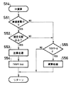
車速Vが所定車速以上であれば、Dレンジで高速クルージング走行していると判断し、ステップS3に進んで現在の変速機油温が規定油温以上か否かを判断する。規定油温未満の場合には変速機油温が高くなるすぎるおそれはないため、ステップS7に進み、牽引モード判定カウンタ積算値STRCNTを零にリセットする。
【0023】
油温が規定油温以上のときには、ステップS4に進み、牽引モード判定カウンタ積算値STRCNTの計算を行い、このように計算された牽引モード判定カウンタ積算値STRCNTに基づいて、高負荷走行モード設定制御(ステップS5)および高負荷走行モード解除制御(ステップS6)が行われる。
【0024】
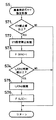
まず、ステップS4における牽引モード判定カウンタ積算値STRCNTの計算制御内容について、図4を参照して説明する。ここでは、まず、登坂判断カウンタ値PNOの演算を行う(ステップS11)。この演算制御内容を図5に示しており、まず、ステップS21において現在の走行路面勾配が所定勾配以上であるか否かを判断する。この走行路面勾配の検出のため、エンジンスロットル開度および車速(および走行加速度)と走行路面勾配との関係を示すテーブルもしくはマップが予め測定もしくは計算されて設定されており、現在のスロットル開度および車速(走行加速度)に対応する路面勾配をこのテーブルから読み取って求める。
【0025】
但し、このように設定されている路面勾配テーブル(マップ)は車両が何も牽引することなく規定車両重量で走行する場合の値を示しており、トレーラ等を牽引している場合にはその牽引負荷を路面勾配として把握できる。例えば、トレーラ等を牽引した状態で平坦路を走行するときには、実際の路面が平坦でもトレーラ等の牽引負荷により所定の勾配の登坂路面を走行していると判断される。このため逆に、このように判断される路面勾配からトレーラ等の牽引の状態を推定することができる。そこで、ステップS21において路面勾配を検出し、トレーラ等を牽引して走行しているか否かの判断を行う。
【0026】
走行路面勾配が所定勾配以上と判断された場合、すなわち、トレーラ等を牽引して走行している可能性があると判断された場合には、ステップS22に進み、トルクコンバータTCのロックアップクラッチLCがタイト係合状態であるか否かを判断する。ロックアップクラッチLCがタイト係合状態であれば、トルクコンバータTCのスリップは無く、その内部発熱量は極く小さいため、ステップS24に進み登坂判断カウンタ値PNOを所定量だけ減算する減算処理(1)を行う。なお、この減算値は、算出された路面勾配値と車速との関係に基づいてテーブル(マップ)状に設定されており、算出路面勾配値および車速の移動平均値に対する減算値をこのテーブルから読み出して求められる。
【0027】
一方、ステップS22においてロックアップクラッチLCがタイト係合状態ではないと判断された場合には、トルクコンバータTCのスリップにより内部発熱が大きくなる可能性が高いため、ステップS23に進み、登坂判断カウンタ値PNOを所定量だけ加算する処理を行う。この加算値も、路面勾配値と車速との関係に基づいてテーブル(マップ)状に設定されており、算出路面勾配値および車速の移動平均値に対する加算値をこのテーブルから読み出して求められる。
【0028】
このようにして加算処理(ステップS23)もしくは減算処理(1)(ステップS24)が行われると、ステップS25においてカウント処理待機タイマTPOFFをセットする。
【0029】
一方、ステップS21において路面勾配が所定勾配未満であると判断された場合にはステップS26に進み、カウント処理待機タイマTPOFFの経過を待った後、ステップS27に進んで路面勾配が下り勾配か否かを判断する。下り勾配でない場合、すなわち、所定勾配未満の上り勾配であるときにはステップS28に示す減算処理(2)を行い、下り勾配のときにはステップS29に示す減算処理(3)を行う。両減算処理(2)および(3)はともに、路面勾配値と車速との関係に基づいて設定された減算値テーブル(マップ)から算出路面勾配値および車速の移動平均値に対する減算値を読み出して減算処理が行われるものであるが、両テーブルでは異なる減算値が設定されている。具体的には、ステップS29の減算処理(3)に用いられるテーブルの方により大きな減算値が設定されている。
【0030】
以上のように、登坂判断カウンタ値PNOはトレーラ等を牽引して走行して走行駆動負荷が大きい状態で、且つロックアップクラッチがタイト係合でなくてトルクコンバータTCからの発熱が大きくなるような状態のときに加算され、それ以外で減算されて演算される値である。このことから分かるように、登坂判断カウンタ値PNOが大きくなると、高負荷走行モードになると考えられる。
【0031】
以上のようにしてステップS11において登坂判断カウンタ値PNOが演算されると、ステップS12に進み、変速頻度カウンタ値FQSHの演算を行う。この演算内容を図6に示しており、まず、ステップS31において今回の変速段指令値SHが前回の変速段指令値SHOと一致しているか否か、すなわち、出力された変速指令に対応する変速が行われたか否かが判断される。SH≠SHOのとき、すなわち変速が行われたときには、ステップS32に進み、第1変速判断タイマTSOFF1が経過したか否か、すなわち前回の変速からこのタイマの設定時間以上経過したか否かが判断される。
【0032】
前回の変速から第1変速判断タイマTSOFF1が経過する前に今回の変速が行われるような高い頻度の変速指令の場合には、変速によるクラッチからの発熱が増大する可能性が高いため、ステップS33に進み、変速頻度カウンタ値FQSHを所定量だけ加算する処理を行う。この加算値は変速機油温との関係に基づいてテーブル(マップ)状に設定されており、現在の変速油温に対する加算値をこのテーブルから読み出して求められる。この後、ステップS34に進み、第1変速判断タイマTSOFF1および第2変速判断タイマTSOFF2をそれぞれ所定値にセットする。
【0033】
一方、ステップS31においてSH=SHOと判断された場合にはそのままステップS36に進む。また、ステップS32において前回の変速から第1変速判断タイマTSOFF1が経過した後に今回の変速が行われたと判断された場合には、第1変速判断タイマTSOFFF1を所定値にセットしてステップS36に進む。ステップS36においては、第2変速判断タイマTSOFF2が経過したか否かを判断する。この経過前である場合には現在変速中であるので、加算処理も減算処理も行わない。第2変速判断タイマTSOFF2が経過しているときには、変速頻度はあまり高くないため、ステップS37に進み、変速頻度カウンタ値FQSHを所定量だけ減算する処理を行う。この減算値は変速機油温との関係に基づいてテーブル(マップ)状に設定されており、現在の変速油温に対する減算値をこのテーブルから読み出して求められる。
【0034】
以上のようにしてステップS12において変速頻度カウンタ値FQSHの演算が行われると、ステップS13に進み、L/C頻度カウンタ値FQLCの演算を行う。この演算内容を図7に示しており、まず、ステップS41においてロックアップクラッチLCの係合制御信号が変化したか否かが判断される。係合制御信号が変化したときには、ステップS42に進み、第1ロックアップ判断タイマTLOFF1が経過したか否か、すなわち前回の係合制御信号変化の時点からこのタイマの設定時間以上経過したか否かが判断される。
【0035】
前回の信号変化の時点から第1ロックアップ判断タイマTLOFF1が経過する前に今回の信号変化が発生するような高い頻度のロックアップ係合制御変更指令の場合には、ロックアップ係合変化によるロックアップクラッチLCおよびトルクコンバータTC内からの発熱が増大する可能性が高いため、ステップS43に進み、ロックアップ頻度カウンタ値FQLCを所定量だけ加算する処理を行う。この加算値は変速機油温との関係に基づいてテーブル(マップ)状に設定されており、現在の変速油温に対する加算値をこのテーブルから読み出して求められる。この後、ステップS44に進み、第1ロックアップ判断タイマTLOFF1および第2ロックアップ判断タイマTLOFF2を所定値にセットする。
【0036】
一方、ステップS41においてロックアップクラッチ係合制御信号の変化が無いと判断された場合にはそのままステップS46に進む。また、ステップS42において前回の信号変化時から第1ロックアップ判断タイマTLOFF1が経過した後に今回の信号変化が発生したと判断された場合には、第1ロックアップ判断タイマTLOFFF1を所定値にセットしてステップS46に進む。ステップS46においては、第2ロックアップ判断タイマTLOFF2が経過したか否かを判断する。この経過前である場合には現在ロックアップ係合制御中であるので、加算処理も減算処理も行わない。一方、第2ロックアップ判断タイマTLOFF2が経過しているときには、係合制御の変更頻度はあまり高くないため、ステップS47に進み、ロックアップ変速頻度カウンタ値FQLCを所定量だけ減算する処理を行う。この減算値は変速機油温との関係に基づいてテーブル(マップ)状に設定されており、現在の変速油温に対する減算値をこのテーブルから読み出して求められる。
【0037】
以上のようにしてステップS13においてL/C頻度カウンタ値FQLCの演算が行われると、ステップS14に進み、車速変動判断カウンタ値DVの演算を行う。この演算内容を図8に示しており、まず、ステップS51において車速変動(車速変動の移動平均値)が小さいか否かが判断される。高速クルージング走行を行うような場合には車速変動が小さいと考えられ、この場合にはステップS52に進み、走行路面勾配が規定勾配以上か否か、すなわち、走行駆動負荷が大きいか否かが判断される。
【0038】
規定勾配以上であるときには、牽引状態での高速クルージング走行の可能性が高く、変速機内部発熱が増大する可能性が高いため、ステップS53に進み、車速変動判断カウンタ値DVを所定量だけ加算する処理を行う。この加算値は変速機油温との関係に基づいてテーブル(マップ)状に設定されており、現在の変速油温に対する加算値をこのテーブルから読み出して求められる。この後、ステップS54に進み、車速変動判断タイマTVOFFを所定値にセットする。
【0039】
一方、ステップS51において車速変動が大きいと判断された場合にはそのままステップS55に進む。また、ステップS52において規定勾配未満の路面勾配であると判断されたときにもステップS55に進む。ステップS55においては、車速変動判断タイマTVOFFが経過したか否かを判断する。この経過前である場合には車速変動が一時的に発生しただけの可能性があるため、この経過後においてもステップS55にくる場合にのみステップS56に進み、車速変動判断カウンタ値DVを所定量だけ減算する処理を行う。なお、この減算値は変速機油温との関係に基づいてテーブル(マップ)状に設定されており、現在の変速油温に対する減算値をこのテーブルから読み出して求められる。
【0040】
以上のようにしてステップS14において車速変動判断カウンタ値DVの演算が行われると、ステップS15に進み、スロットル変動判断カウンタ値DTHの演算を行う。この演算内容を図9に示しており、まず、ステップS61においてスロットル変動(スロットル変動の移動平均値)が大きいか否かが判断される。高速クルージング走行を行うような場合にはスロットル開度はほぼ一定のままで走行すると考えられ、この場合にはステップS62に進み、スロットル変動判断カウンタ値DTHを所定量だけ加算する処理を行う。この加算値は変速機油温との関係に基づいてテーブル(マップ)状に設定されており、現在の変速油温に対する加算値をこのテーブルから読み出して求められる。この後、ステップS54に進み、スロットル変動判断タイマTHOFFを所定値にセットする。
【0041】
一方、ステップS61において車速変動が大きいと判断された場合にはそのままステップS64に進み、スロットル変動判断タイマTHOFFが経過したか否かを判断する。この経過前である場合にはスロットル変動が一時的の可能性があるため、この経過後においてもステップS64にくる場合のみステップS65に進み、スロットル変動判断カウンタ値DTHを所定量だけ減算する処理を行う。なお、この減算値は変速機油温との関係に基づいてテーブル(マップ)状に設定されており、現在の変速油温に対する減算値をこのテーブルから読み出して求められる。
【0042】
以上のように、ステップS11〜S15において、登坂判断カウンタ値PNO、変速頻度カウンタ値FQSH、L/C頻度カウンタ値FQLC、車速変動判断カウンタ値DV、スロットル変動判断カウンタ値DTHが算出されると、これらカウンタ値を合計して牽引モード判定カウンタ値TRCNTが演算される(ステップS16)。さらに、このカウンタ値TRCNTを積算して牽引モード判定カウンタ積算値STRCNTが演算される(ステップS17)。
【0043】
以上のようにして図3におけるステップS4に示す牽引モード判定カウンタ積算値STRCNTが計算されると、この牽引モード判定カウンタ積算値STRCNTの値に基づいて、ステップS5における高負荷走行モード設定制御が行われる。この制御内容を図10に示しており、この制御内容について図2のタイムチャートを併用して説明する。このタイムチャートは横軸に時間を示し、時間t0において牽引モード判定カウンタ積算値STRCNTの加算が開始され、牽引モード判定カウンタ積算値STRCNTが徐々に大きくなっていく場合における各値の時間変化特性を示している。
【0044】
この制御においては、まず、ステップS71において牽引モード判定カウンタ積算値STRCNTが5TH禁止値TRCNT(1)以上であるか否かが判断される。上述の説明から分かるように、ステップS4において計算される牽引モード判定カウンタ積算値STRCNTは、トレーラ等を牽引して高速クルージング走行を行うような場合に変速機油温が上昇する要因に応じてカウンタ値を加算して求められる積算値であり、この値が大きいほど変速機油温が高くなると判断できる。例えば、図2の場合には時間t0からステップS4における加算処理が開始されて牽引モード判定カウンタ積算値STRCNTが徐々に大きくなり、時間t1においてこの値が5TH禁止値TRCNT(1)を越える。
【0045】
このため、時間t1までの間はステップS71からそのままこの制御は終了するが、時間t1以後はステップS71からステップS72に進み5TH設定禁止制御を行う。この制御内容を図11に示している。この制御は第5速(5TH変速段)の設定を禁止するもので、第5速で走行しているときには第4速にシフトダウンをさせるとともに第4速以下のときには第5速へのシフトアップを規制する制御がなされる。
【0046】
このため、まず、ステップS81において現在の変速段が第5速か否かが判断される。第5速ではないときにはステップS85に進み、これ以降は第5速へのシフトアップを規制する制御が行われる。また、第5速で走行中であるときには、ステップS82においてアクセルペダルが踏み込まれたか(スロットル開度が増加したか)の判断、より具体的には所定時間内に所定以上のスロットル開度増加があったかの判断がなされる。アクセルペダルが踏み込まれた場合にはステップS84に進み、第4速へのシフトダウンを行わせる。アクセルペダルが踏み込まれない場合でも、ステップS83においてシフトダウン指令があったか否か(例えば、シフトレバー操作によるシフトダウン指令、車速低下によるシフトダウン指令等があったか否か)の判断がなされ、シフトダウン指令が出された場合にはステップS84に進み、第4速へのシフトダウンを行わせる。
【0047】
以上のようにして5TH設定禁止制御(ステップS72)が開始されるとこの時点で5TH設定禁止フラグF(5TH)が立てられる(ステップS73)。このように時間t1においてこの牽引モード判定カウンタ積算値STRCNTが5TH禁止値TRCNT(1)を越えた後、上記のようにアクセルペダル踏み込みもしくはシフトダウン指令を待って5TH設定禁止制御が開始されて5TH設定禁止フラグF(5TH)が立てられるため、タイムチャートでは時間t2において5TH設定禁止フラグF(5TH)が立てられている。
【0048】
このようにして5TH設定禁止制御が開始された後においてもトレーラ等を牽引して走行する状態(牽引走行状態)が継続して牽引モード判定カウンタ値TRCNTが正の値であれば、上述した各加算処理は継続され牽引モード判定カウンタ積算値STRCNTは徐々に増加する。これに応じて、牽引モード判定カウンタ積算値STRCNTがL/Cタイト判断値TRCNT(2)以上となったと判断されると(ステップS74)、ステップS75に進み、トルクコンバータTCのロックアップクラッチLCをタイト結合にする制御が行われる(タイムチャートの時間t3)とともに、L/Cタイト設定フラグF(L/C)が立てられる。
【0049】
この後、下り坂走行となって走行駆動負荷が小さくなるなどして牽引モード判定カウンタ値TRCNTが負の値となれば(時間t4)、変速機内部発熱が減少するモードとなるので、牽引モード判定カウンタ積算値STRCNTの計算においても減算処理を行わせても良いのであるが、この減算処理はカウンタ減算ディレータイマの経過を待って時間t5から開始される。なお、牽引モード判定カウンタ積算値STRCNTの最大値が予め設定されており、最大値以上となる加算処理は行われない。
【0050】
時間t5から減算処理が開始されると、図3のステップS6に示す高負荷走行モード解除制御に移行するが、これについて図12を参照して説明する。ここではまず、L/Cタイト設定フラグF(L/C)が立てられているか否か(F(L/C)=1か否か)が判断され(ステップS91)、F(L/C)=1のときにはステップS92に進み、牽引モード判定カウンタ積算値STRCNTがL/Cタイト解除値TRCNT(3)以下となったか否かが判断される。図2に示すように、時間t6において上記減算処理により牽引モード判定カウンタ積算値STRCNTがL/Cタイト解除値TRCNT(3)以下となる。このため、この時点からステップS93,S94に進み、ロックアップクラッチLCの係合制御を通常制御に戻すとともにL/Cタイト設定フラグF(L/C)を0に戻す。
【0051】
但し、ロックアップクラッチLCの係合制御を通常制御に戻すタイミングは、時間t6において牽引モード判定カウンタ積算値STRCNTがL/Cタイト解除値TRCNT(3)以下となった後に、アクセルペダルが踏み込まれたり、シフトダウン指令があったりしたときに行われ、図2に示すように時間t7において通常制御に戻される。
【0052】
このようにしてロックアップクラッチLCの係合制御が通常制御に戻されてL/Cタイト設定フラグF(L/C)が0になると、次のフローではステップS91からステップS95に進み、牽引モード判定カウンタ積算値STRCNTが5TH禁止解除値TRCNT(4)以下となったかが判断される。牽引モード判定カウンタ積算値STRCNTが5TH禁止解除値TRCNT(4)以下となると(時間t8)、ステップS96,S97に進み、5TH設定禁止制御が解除されるとともに、5TH設定禁止フラグF(5TH)が0に戻される。
【0053】
以上説明した制御を行っているときに、牽引モード判定カウンタ積算値STRCNTが所定値の状態で車両を停止させてイグニッションスイッチをオフにしてエンジンを停止することもある。このような場合に、イグニッションスイッチを再びオンにしてエンジンを始動させて走行を再開した場合での牽引モード判定カウンタ積算値STRCNTの扱いが問題となる。このため、イグニッションスイッチオフ時に牽引モード判定カウンタ積算値STRCNTおよび変速機油温を記憶しておく。そして、イグニッションスイッチオン時に変速機油温を検出して記憶された変速機油温と比較して油温の変化を求め、この油温変化に対応して牽引モード判定カウンタ積算値STRCNTを減算処理して補正するように構成されている。これにより、一時的に停車して休憩するような場合にも、牽引モード判定カウンタ積算値STRCNTを常にそのときの変速機油温に対応した適切な値に設定して、エンジン再始動後においても良好な制御が可能となる。
【0054】
【発明の効果】
以上説明したように、本発明に係る車両用自動変速機の制御装置は、車両の運転状態に基づいて車両が牽引走行状態となったことを推定する牽引状態推定手段と、この牽引状態推定手段により車両が牽引走行状態となったことが推定されたときに、トルクコンバータのロックアップクラッチの締結量を増加させるロックアップ締結増加機構とを有する。なお、この牽引状態推定手段は、例えば、車両がトレーラを牽引して走行することにより駆動負荷が増加して車両が牽引走行状態となったことを推定するように構成される。
【0055】
このような構成の本発明に係る車両用自動変速機の制御装置によれば、例えば、トレーラ等を牽引して高速クルージング走行するような場合に、牽引負荷が加わることにより車両が牽引走行状態となったことが牽引状態推定手段により推定されるとトルクコンバータのロックアップクラッチの締結量が増加される(すなわちタイトな締結にされる)ので、トルクコンバータ内でのスリップ量が低下されてトルクコンバータからの発熱が抑えられ、変速機内部油温上昇が抑えられる。
【0056】
本発明に係る制御装置ではさらに、牽引状態推定手段により車両が牽引走行状態となったことが推定されたときには自動変速機構が最高速度段に変速することを禁止し、また、最高速度段で走行中のときにはシフトダウンさせるように構成し、シフトダウンの後においても、牽引状態推定手段により車両が牽引走行状態となったことが推定されたときにはロックアップ締結増加機構によりロックアップクラッチの締結量を増加させるように構成している。
【0057】
このため、本発明の制御装置においては、車両が牽引走行状態になったことが推定されると最高速度段の設定が禁止され、少なくとも最高速度段より低速の速度段での走行となるため、トルクコンバータの駆動トルクが小さくなってその駆動負荷が低減され、トルクコンバータからの発熱が抑制される。そして、この後においてもまだ牽引走行状態であるときには、トルクコンバータのロックアップクラッチの締結量が増加されてトルクコンバータ内でのスリップ量が低下されて内部発熱が抑えられる。この結果、牽引走行等による牽引走行状態に対して、変速機の内部発熱を段階的に低下させて、変速機内部油温が過度に上昇することを効果的に抑制できる。
【0058】
なお、牽引状態推定手段は、車両の走行駆動負荷、変速頻度、ロックアップクラッチの作動頻度、車速変動、スロットル開度変動に基づいて牽引走行状態か否かの判断を行うように構成するのが好ましい。これにより、トレーラ等の牽引走行による牽引走行状態を正確且つ的確に判断することができる。
【0059】
車両が最高速度段で走行中のときに前記牽引状態推定手段により前記車両が牽引走行状態となったことが推定されてシフトダウンさせるときには、アクセルペダルの踏み込みもしくはシフトダウン指令を待ってシフトダウンを行わせるのが好ましい。これにより、シフトダウンを違和感無く行わせることができる。
【0060】
なお、牽引状態推定手段により車両が牽引走行状態となったことが推定されているときにこの車両を停止させ、その後にこの車両を再び走行させるときには、車両を停止させている間における変速機油温の低下状態に基づいて車両の牽引走行状態を推定するのが好ましい。これにより、車両を一時的に停止させた場合におけるその後の走行においても適切な制御が可能となる。
【図面の簡単な説明】
【図1】本発明に係る車両用自動変速機およびその制御装置の構成を示す概略図である。
【図2】上記制御装置により上記自動変速機の制御を行う場合の種々の特性の時間変化を示すタイムチャートである。
【図3】上記制御装置による牽引モード走行制御内容を示すフローチャートである。
【図4】牽引モード判定カウンタ積算値STRCNTの計算制御内容を示すフローチャートである。
【図5】登坂判断カウンタ値の演算制御内容を示すフローチャートである。
【図6】変速頻度カウンタ値の演算制御内容を示すフローチャートである。
【図7】L/C頻度カウンタ値の演算制御内容を示すフローチャートである。
【図8】車速変動判断カウンタ値の演算制御内容を示すフローチャートである。
【図9】スロットル変動判断カウンタ値の演算制御内容を示すフローチャートである。
【図10】高負荷走行モード設定制御内容を示すフローチャートである。
【図11】 5TH設定禁止制御内容を示すフローチャートである。
【図12】高負荷走行モード解除制御内容を示すフローチャートである。
【符号の説明】
E エンジン
TM 変速機
TC トルクコンバータ
LC ロックアップクラッチ
CV 変速制御バルブ[0001]
BACKGROUND OF THE INVENTION
The present invention relates to a vehicular automatic transmission that shifts engine output and transmits it to wheels to drive the vehicle, and more particularly to an automatic transmission when the vehicle is running while towing a trailer or the like. The present invention relates to a device that performs control.
[0002]
[Prior art]
2. Description of the Related Art Conventionally, automatic transmissions for vehicles include a combination of a torque converter and a transmission mechanism (for example, a gear type transmission mechanism) that has been put into practical use. In this automatic transmission, for example, shift control is performed such that the shift is automatically performed according to the throttle opening of the engine (drive source) and the vehicle speed, and the vehicle starts off from the low speed shift stage and increases in traveling speed. In general, control is performed such that the gears are gradually shifted up and the maximum speed stage is set in high-speed cruising.
[0003]
There is a case where a trailer, a camper, or the like is connected to the rear portion of a vehicle having such an automatic transmission and the vehicle is towed (a traveling body to be pulled in this way is collectively referred to as a trailer). In this way, when the vehicle is towed by a trailer or the like, a traction load such as a trailer is applied to the vehicle, so that the shift control during towing is required to be different from the shift control during normal traveling.
[0004]
For this reason, for example, Japanese Patent Application Laid-Open No. 61-135881 provides a detector comprising a switch for detecting whether or not a trailer is connected to a trailer towing hitch. A shift control device is disclosed in which, when it is detected that the trailer is connected, the shift position of the transmission is limited to a predetermined shift position on the low speed side. Japanese Patent Application Laid-Open No. 8-164732 provides a limit switch for detecting a traction weight in a coupler that connects a trailer, and an operating force of a retarder device or an auxiliary brake device based on the traction weight detected by the limit switch. Is disclosed.
[0005]
[Problems to be solved by the invention]
By the way, when the vehicle performs high-speed traveling (high-speed cruising traveling) on a flat road with a trailer or the like being pulled, the traveling load is larger than when the vehicle is not towed. For this reason, a state in which a high load and high speed rotation operation occurs in a state where the speed ratio of the torque converter is smaller than 1.0 occurs, heat generation from the torque converter or the like increases, and the oil temperature inside the transmission tends to increase. There is. In addition, due to the effects of load fluctuations during high-load running, shift down and shift up are repeated frequently, and the torque converter lockup clutch is frequently turned on and off repeatedly, increasing the internal heat generation of the transmission. There is also a problem that the driving feeling is reduced.
[0006]
The present invention has been made in view of such a problem, and an automatic transmission that can suppress a rise in the oil temperature of the transmission and can perform a comfortable high-speed cruising traveling even when the trailer or the like is pulled to travel at a high speed. An object is to provide a control device.
[0007]
[Means for Solving the Problems]
In order to achieve such an object, the present invention includes a torque converter connected to a drive source (for example, the engine E in the embodiment) and an automatic transmission mechanism connected to the output side of the torque converter. An automatic transmission for a vehicle is configured, and driving force from a drive source that has been shifted through a torque converter and an automatic transmission mechanism is transmitted to wheels to drive the vehicle. The control device for an automatic transmission for a vehicle includes a traction state estimation unit that estimates that the vehicle is in a traction running state based on a driving state of the vehicle, and the traction state estimation unit causes the vehicle to be in a traction running state. A lockup engagement increasing mechanism that increases the engagement amount of the lockup clutch of the torque converter.
[0008]
The control device according to the present invention further prohibits the automatic transmission mechanism from shifting to the maximum speed stage when it is estimated by the traction state estimation means that the vehicle is in the traction running state, and at the maximum speed stage. It is configured to shift down when the vehicle is traveling, and even after the shift down, when the vehicle is estimated to be in the towed traveling state by the towed state estimating means, the lockup clutch engagement amount is increased by the lockup engagement increasing mechanism. Configured to increase.
[0009]
The traction state estimation means may be configured to determine whether or not the vehicle is in the traction traveling state based on the vehicle travel drive load, the shift frequency, the lockup clutch operation frequency, the vehicle speed variation, and the throttle opening variation. For example, traction mode determination counter integrated value in the embodiment STRCNT The means for calculating this corresponds to this. Thereby, it is possible to accurately and accurately determine the towing traveling state by the towing traveling of the trailer or the like.
[0010]
According to the control device for an automatic transmission for a vehicle according to the present invention having such a configuration, for example, when the vehicle is towed at a high speed by cruising a trailer or the like, the vehicle is brought into a towed running state by applying a towing load. If it is estimated by the traction state estimation means, the engagement amount of the lock-up clutch of the torque converter is increased (that is, the engagement is tight), so that the slip amount in the torque converter is reduced and the torque converter The heat generation from the is suppressed, and the oil temperature rise inside the transmission is suppressed.
[0011]
According to the invention,If it is estimated that the vehicle is in a towed running state, setting of the maximum speed stage is prohibited, and at least the speed stage is lower than the maximum speed stage, so that the driving torque of the torque converter is reduced and the driving is performed. The load is reduced and heat generation from the torque converter is suppressed. Even after this, when the vehicle is still in the towed running state, the engagement amount of the lock-up clutch of the torque converter is increased, the slip amount in the torque converter is decreased, and internal heat generation is suppressed. As a result, the internal heat generation of the transmission can be reduced stepwise with respect to the traction running state due to traction running or the like, and it is possible to effectively prevent the transmission internal oil temperature from rising excessively.
[0012]
When it is estimated that the vehicle is in a towed traveling state by the towed state estimating means when the vehicle is traveling at the maximum speed stage, the downshift is performed after the accelerator pedal is depressed or a downshift command is issued. It is preferred to do so. Thereby, downshifting can be performed without a sense of incongruity.
[0013]
When it is estimated that the vehicle is in a towed running state by the towed state estimating means, and when the vehicle is driven again after that, the transmission oil temperature during the stop of the vehicle is reduced. It is preferable to estimate the towing travel state of the vehicle based on the lowered state. As a result, it is possible to perform appropriate control in the subsequent travel when the vehicle is temporarily stopped.
[0014]
DETAILED DESCRIPTION OF THE INVENTION
Hereinafter, preferred embodiments of the present invention will be described with reference to the drawings. FIG. 1 shows the configuration of an automatic transmission for a vehicle having a control device according to the present invention. The power transmission device having the automatic transmission TM is configured to shift the output rotation of the engine E and transmit it to the left and
[0015]
A transmission TM is connected to the engine E, and the rotation of the output shaft Es of the engine E is transmitted to the transmission TM. The transmission TM includes a torque converter TC connected to the output shaft Es of the engine E and a gear-type transmission mechanism connected to the output side of the torque converter TC. The gear-type transmission mechanism includes a
[0016]
Generally, in a transmission for a vehicle, a plurality of gear trains (for example, in the present embodiment, having 5 forward gears and 5 gear trains) corresponding to the gears are arranged. However, in this gear-type transmission mechanism, only the
[0017]
A shift control valve CV is provided for controlling the engagement of the shift clutches 13c and 14c. The supply of the engagement hydraulic pressure is controlled from the shift control valve CV to the shift clutches 13c and 14c. Joint control is performed. The operation of the shift control valve CV is controlled by a built-in electromagnetic valve, and controls the operation of the electromagnetic valve based on a control signal from the electronic control unit ECU, and the engagement hydraulic pressure for the shift clutches 13c and 14c is controlled. Supply control is performed. Note that the automatic transmission TM of the present embodiment is provided with five gear trains for forward movement, and automatic transmission of five forward speeds is performed by selectively using any one of these gear trains with a shift control valve. It is configured to be
[0018]
An output drive gear 15a is coupled to the
[0019]
In the power transmission device having the above configuration, the electronic control unit ECU that controls the operation of the control valve CV has a detection signal from the
[0020]
The control valve CV controls the engagement / disengagement of the clutch of the gear-type transmission mechanism to perform the automatic transmission control and the engagement control of the lockup clutch LC. The operation of the control valve CV is performed by the electronic control unit ECU. Be controlled. In the present invention, there is a feature in the control content by the electronic control unit ECU when the trailer or the like is pulled to perform high-speed cruising traveling, and this control content will be described below.
[0021]
This control performs shift control and lock-up engagement control so as to prevent the transmission oil temperature from becoming too high in the case of high-speed cruising while towing a trailer or the like. This is performed according to the flow of FIG. First, it is determined whether or not it is in the D range (D5, D4, D3 range) (step S1), and in other ranges, for example, in the 2 range, L range, N range, and R range, the traction mode determination counter integrated value STRCNT Is subtracted by a predetermined amount (step S8). On the other hand, if it is the D range, the process proceeds to step S2, and it is determined whether or not the current vehicle speed V is equal to or higher than a predetermined vehicle speed (for example, whether or not the vehicle is in a high speed state where the speed is 80 km / h or higher). In S8, the traction mode determination counter integrated value STRCNT is subtracted by a predetermined amount. The subtraction value per time in step S8 is set in a table (map) based on the relationship between the calculated road surface gradient value and the vehicle speed, and the subtraction value is calculated from the calculated road surface gradient value and the moving average value of the vehicle speed. The value is obtained by reading from this table.
[0022]
If the vehicle speed V is equal to or higher than the predetermined vehicle speed, it is determined that the vehicle is traveling at high speed in the D range, and the process proceeds to step S3 to determine whether the current transmission oil temperature is equal to or higher than the specified oil temperature. If the oil temperature is lower than the specified oil temperature, there is no possibility that the transmission oil temperature becomes too high, so the process proceeds to step S7, and the traction mode determination counter integrated value STRCNT is reset to zero.
[0023]
When the oil temperature is equal to or higher than the specified oil temperature, the process proceeds to step S4, where the traction mode determination counter integrated value STRCNT is calculated. Based on the calculated traction mode determination counter integrated value STRCNT, the high load travel mode setting control is performed. (Step S5) and high load travel mode release control (Step S6) are performed.
[0024]
First, the calculation control contents of the traction mode determination counter integrated value STRCNT in step S4 will be described with reference to FIG. Here, first, an uphill determination counter value PNO is calculated (step S11). The contents of this arithmetic control are shown in FIG. 5. First, in step S21, it is determined whether or not the current road surface gradient is equal to or greater than a predetermined gradient. In order to detect the traveling road surface gradient, a table or map showing the relationship between the engine throttle opening and the vehicle speed (and traveling acceleration) and the traveling road surface gradient is set in advance by measurement or calculation. The road surface gradient corresponding to the vehicle speed (running acceleration) is obtained from this table.
[0025]
However, the road gradient table (map) set in this way shows the value when the vehicle travels with the specified vehicle weight without towing anything, and when towing a trailer etc. The load can be grasped as a road surface gradient. For example, when traveling on a flat road while towing a trailer or the like, it is determined that the vehicle is traveling on an uphill road surface having a predetermined gradient by a towing load such as a trailer even if the actual road surface is flat. Therefore, conversely, the towing state of the trailer or the like can be estimated from the road surface gradient determined in this way. Therefore, in step S21, the road surface gradient is detected, and it is determined whether or not the vehicle is traveling by pulling a trailer or the like.
[0026]
When it is determined that the traveling road surface gradient is equal to or greater than the predetermined gradient, that is, when it is determined that there is a possibility of traveling by pulling a trailer or the like, the process proceeds to step S22, and the lock-up clutch LC of the torque converter TC. Is determined to be in a tight engagement state. If the lockup clutch LC is in the tight engagement state, there is no slip of the torque converter TC and the internal heat generation amount is extremely small, so the process proceeds to step S24 and the subtraction process (1) for subtracting the climbing judgment counter value PNO by a predetermined amount. )I do. This subtraction value is set in a table (map) based on the relationship between the calculated road gradient value and the vehicle speed, and the subtraction value for the calculated road gradient value and the moving average value of the vehicle speed is read from this table. Is required.
[0027]
On the other hand, if it is determined in step S22 that the lockup clutch LC is not in the tight engagement state, there is a high possibility that internal heat generation will increase due to slippage of the torque converter TC. A process of adding a predetermined amount of PNO is performed. This addition value is also set in a table (map) based on the relationship between the road surface gradient value and the vehicle speed, and the addition value for the calculated road surface gradient value and the moving average value of the vehicle speed is read out from this table.
[0028]
When the addition process (step S23) or the subtraction process (1) (step S24) is performed in this way, the count process standby timer TPOFF is set in step S25.
[0029]
On the other hand, if it is determined in step S21 that the road surface gradient is less than the predetermined gradient, the process proceeds to step S26, waits for the count processing standby timer TPOFF to elapse, and then proceeds to step S27 to determine whether or not the road surface gradient is a downward gradient. to decide. When it is not a downward gradient, that is, when it is an upward gradient less than a predetermined gradient, the subtraction process (2) shown in step S28 is performed, and when it is a downward gradient, the subtraction process (3) shown in step S29 is performed. In both subtraction processes (2) and (3), the calculated road surface gradient value and the subtraction value for the moving average value of the vehicle speed are read from the subtraction value table (map) set based on the relationship between the road surface gradient value and the vehicle speed. Although subtraction processing is performed, different subtraction values are set in both tables. Specifically, a larger subtraction value is set in the table used for the subtraction process (3) in step S29.
[0030]
As described above, the uphill determination counter value PNO is driven by towing a trailer or the like so that the travel drive load is large, and the lockup clutch is not tightly engaged and heat generation from the torque converter TC increases. It is a value that is added when it is in the state and subtracted otherwise. As can be seen from this, it is considered that the high load traveling mode is entered when the uphill determination counter value PNO increases.
[0031]
When the uphill determination counter value PNO is calculated in step S11 as described above, the process proceeds to step S12, and the shift frequency counter value FQSH is calculated. The contents of this calculation are shown in FIG. 6. First, in step S31, whether or not the current gear position command value SH matches the previous gear position command value SHO, that is, the gear shift corresponding to the output gear shift command. It is determined whether or not has been performed. When SH ≠ SHO, that is, when a shift is performed, the process proceeds to step S32, where it is determined whether or not the first shift determination timer TSOFF1 has elapsed, that is, whether or not the set time of this timer has elapsed since the previous shift. Is done.
[0032]
In the case of a shift command having a high frequency such that the current shift is performed before the first shift determination timer TSOFF1 elapses from the previous shift, there is a high possibility that heat generated from the clutch due to the shift is increased, so step S33. Then, the process of adding the shift frequency counter value FQSH by a predetermined amount is performed. This addition value is set in a table (map) based on the relationship with the transmission oil temperature, and the addition value for the current transmission oil temperature is read out from this table. Thereafter, the process proceeds to step S34, and the first shift determination timer TSOFF1 and the second shift determination timer TSOFF2 are set to predetermined values, respectively.
[0033]
On the other hand, if it is determined in step S31 that SH = SHO, the process directly proceeds to step S36. If it is determined in step S32 that the current shift has been performed after the first shift determination timer TSOFF1 has elapsed since the previous shift, the first shift determination timer TSOFFF1 is set to a predetermined value, and the process proceeds to step S36. . In step S36, it is determined whether second shift determination timer TSOFF2 has elapsed. If it is before this lapse, the gear is currently being shifted, so neither addition nor subtraction is performed. When the second shift determination timer TSOFF2 has elapsed, the shift frequency is not so high, the process proceeds to step S37, and a process of subtracting the shift frequency counter value FQSH by a predetermined amount is performed. This subtraction value is set in a table (map) based on the relationship with the transmission oil temperature, and the subtraction value for the current transmission oil temperature is read out from this table.
[0034]
When the shift frequency counter value FQSH is calculated in step S12 as described above, the process proceeds to step S13, and the L / C frequency counter value FQLC is calculated. The contents of this calculation are shown in FIG. 7. First, in step S41, it is determined whether or not the engagement control signal of the lockup clutch LC has changed. When the engagement control signal is changed, the process proceeds to step S42, whether or not the first lockup determination timer TLOFF1 has elapsed, that is, whether or not the set time of this timer has elapsed since the previous engagement control signal change. Is judged.
[0035]
In the case of a lockup engagement control change command with a high frequency such that the current signal change occurs before the first lockup determination timer TLOFF1 elapses from the time of the previous signal change, the lock due to the lockup engagement change Since there is a high possibility that the heat generated from the up clutch LC and the torque converter TC will increase, the process proceeds to step S43, and a process of adding the lockup frequency counter value FQLC by a predetermined amount is performed. This addition value is set in a table (map) based on the relationship with the transmission oil temperature, and the addition value for the current transmission oil temperature is read out from this table. Thereafter, the process proceeds to step S44, and the first lockup determination timer TLOFF1 and the second lockup determination timer TLOFF2 are set to predetermined values.
[0036]
On the other hand, if it is determined in step S41 that there is no change in the lockup clutch engagement control signal, the process directly proceeds to step S46. If it is determined in step S42 that the current signal change has occurred after the first lockup determination timer TLOFF1 has elapsed since the previous signal change, the first lockup determination timer TLOFFF1 is set to a predetermined value. Then, the process proceeds to step S46. In step S46, it is determined whether the second lockup determination timer TLOFF2 has elapsed. If it is before this time, the lock-up engagement control is currently being performed, so neither addition processing nor subtraction processing is performed. On the other hand, when the second lockup determination timer TLOFF2 has elapsed, the change frequency of the engagement control is not so high, so the process proceeds to step S47, where a process of subtracting the lockup shift frequency counter value FQLC by a predetermined amount is performed. This subtraction value is set in a table (map) based on the relationship with the transmission oil temperature, and the subtraction value for the current transmission oil temperature is read out from this table.
[0037]
As described above, when the calculation of the L / C frequency counter value FQLC is performed in step S13, the process proceeds to step S14, and the vehicle speed variation determination counter value DV is calculated. FIG. 8 shows the contents of this calculation. First, in step S51, it is determined whether or not the vehicle speed fluctuation (moving average value of the vehicle speed fluctuation) is small. When performing high-speed cruising traveling, it is considered that the vehicle speed fluctuation is small. In this case, the process proceeds to step S52, where it is determined whether or not the traveling road surface gradient is greater than or equal to the specified gradient, that is, whether or not the traveling drive load is large. Is done.
[0038]
When the slope is equal to or greater than the specified slope, there is a high possibility of high-speed cruising traveling in the towing state, and there is a high possibility that the internal heat generation of the transmission will increase. Process. This addition value is set in a table (map) based on the relationship with the transmission oil temperature, and the addition value for the current transmission oil temperature is read out from this table. Thereafter, the process proceeds to step S54, and the vehicle speed fluctuation determination timer TVOFF is set to a predetermined value.
[0039]
On the other hand, if it is determined in step S51 that the vehicle speed fluctuation is large, the process directly proceeds to step S55. In addition, when it is determined in step S52 that the road surface gradient is less than the specified gradient, the process proceeds to step S55. In step S55, it is determined whether or not the vehicle speed fluctuation determination timer TVOFF has elapsed. If it is before this time, there is a possibility that the vehicle speed fluctuation has only temporarily occurred. Therefore, even after this time, the process proceeds to step S56 only when it comes to step S55, and the vehicle speed fluctuation judgment counter value DV is set to a predetermined amount. Only the subtraction process is performed. The subtraction value is set in a table (map) based on the relationship with the transmission oil temperature, and the subtraction value for the current transmission oil temperature is obtained from this table.
[0040]
When the calculation of the vehicle speed fluctuation determination counter value DV is performed in step S14 as described above, the process proceeds to step S15, and the throttle fluctuation determination counter value DTH is calculated. FIG. 9 shows the contents of this calculation. First, in step S61, it is determined whether or not the throttle fluctuation (moving average value of the throttle fluctuation) is large. When performing high-speed cruising running, it is considered that the throttle opening is kept substantially constant. In this case, the process proceeds to step S62, and a process of adding the throttle fluctuation determination counter value DTH by a predetermined amount is performed. This addition value is set in a table (map) based on the relationship with the transmission oil temperature, and the addition value for the current transmission oil temperature is read out from this table. Thereafter, the process proceeds to step S54, and the throttle fluctuation determination timer THOFF is set to a predetermined value.
[0041]
On the other hand, if it is determined in step S61 that the vehicle speed fluctuation is large, the process proceeds to step S64 as it is, and it is determined whether or not the throttle fluctuation determination timer THOFF has elapsed. If it is before this time, the throttle fluctuation may be temporary, so even after this time, the process proceeds to step S65 only when it comes to step S64, and the process of subtracting the throttle fluctuation judgment counter value DTH by a predetermined amount is performed. Do. The subtraction value is set in a table (map) based on the relationship with the transmission oil temperature, and the subtraction value for the current transmission oil temperature is obtained from this table.
[0042]
As described above, when the uphill determination counter value PNO, the shift frequency counter value FQSH, the L / C frequency counter value FQLC, the vehicle speed variation determination counter value DV, and the throttle variation determination counter value DTH are calculated in steps S11 to S15, These counter values are summed to calculate the traction mode determination counter value TRCNT (step S16). Further, the traction mode determination counter integrated value STRCNT is calculated by integrating the counter value TRCNT (step S17).
[0043]
When the traction mode determination counter integrated value STRCNT shown in step S4 in FIG. 3 is calculated as described above, the high load traveling mode setting control in step S5 is performed based on the value of the traction mode determination counter integrated value STRCNT. Is called. This control content is shown in FIG. 10, and this control content will be described with reference to the time chart of FIG. This time chart shows time on the horizontal axis. At time t0, the addition of the traction mode determination counter integrated value STRCNT starts, and the time change characteristics of each value when the traction mode determination counter integrated value STRCNT gradually increases are shown. Show.
[0044]
In this control, first, in step S71, it is determined whether or not the traction mode determination counter integrated value STRCNT is equal to or greater than the 5TH prohibited value TRCNT (1). As can be seen from the above description, the traction mode determination counter integrated value STRCNT calculated in step S4 is a counter value corresponding to a factor that increases the transmission oil temperature in the case of high speed cruising traveling by pulling a trailer or the like. It can be determined that the transmission oil temperature increases as this value increases. For example, in the case of FIG. 2, the addition process in step S4 is started from time t0, and the traction mode determination counter integrated value STRCNT gradually increases, and this value exceeds the 5TH prohibited value TRCNT (1) at time t1.
[0045]
For this reason, this control is directly terminated from step S71 until time t1, but after time t1, the process proceeds from step S71 to step S72 and 5TH setting prohibition control is performed. The contents of this control are shown in FIG. This control prohibits the setting of the fifth speed (5TH shift stage). When the vehicle is traveling at the fifth speed, it is shifted down to the fourth speed, and when it is lower than the fourth speed, it is shifted up to the fifth speed. The control which regulates is made.
[0046]
Therefore, first, in step S81, it is determined whether or not the current shift speed is the fifth speed. When it is not the fifth speed, the process proceeds to step S85, and thereafter, control for restricting the upshift to the fifth speed is performed. When the vehicle is traveling at the fifth speed, it is determined in step S82 whether or not the accelerator pedal has been depressed (whether the throttle opening has increased). More specifically, the throttle opening has increased more than a predetermined amount within a predetermined time. Judgment is made if there was. If the accelerator pedal is depressed, the process proceeds to step S84 to shift down to the fourth speed. Even when the accelerator pedal is not depressed, it is determined whether or not there is a downshift command in step S83 (for example, whether there is a downshift command due to shift lever operation, a downshift command due to a decrease in vehicle speed, etc.). When is issued, the process proceeds to step S84 to shift down to the fourth speed.
[0047]
When the 5TH setting prohibition control (step S72) is started as described above, the 5TH setting prohibition flag F (5TH) is set at this point (step S73). As described above, after the traction mode determination counter integrated value STRCNT exceeds the 5TH prohibition value TRCNT (1) at time t1, the 5TH setting prohibition control is started after waiting for the accelerator pedal depression or downshift command as described above. Since the setting prohibition flag F (5TH) is set, the 5TH setting prohibition flag F (5TH) is set at time t2 in the time chart.
[0048]
Even when the 5TH setting prohibition control is started in this manner, the state in which the trailer is towed and traveled (towed traveling state) continues and the tow mode determination counter value TRCNT is a positive value, The addition process is continued, and the traction mode determination counter integrated value STRCNT gradually increases. Accordingly, when it is determined that the traction mode determination counter integrated value STRCNT is equal to or greater than the L / C tight determination value TRCNT (2) (step S74), the process proceeds to step S75, and the lockup clutch LC of the torque converter TC is turned on. The tight coupling control is performed (time t3 in the time chart), and the L / C tight setting flag F (L / C) is set.
[0049]
After this, if the traction mode determination counter value TRCNT becomes a negative value (time t4) due to downhill traveling, the travel drive load is reduced, etc., the transmission internal heat generation is reduced. The subtraction process may be performed also in the calculation of the determination counter integrated value STRCNT, but this subtraction process is started from time t5 after the counter subtraction delay timer has elapsed. Note that the maximum value of the traction mode determination counter integrated value STRCNT is set in advance, and an addition process that exceeds the maximum value is not performed.
[0050]
When the subtraction process is started from time t5, the process shifts to the high-load traveling mode release control shown in step S6 of FIG. 3, which will be described with reference to FIG. Here, it is first determined whether or not the L / C tight setting flag F (L / C) is set (whether F (L / C) = 1) (step S91), and F (L / C). When = 1, the process proceeds to step S92, and it is determined whether or not the traction mode determination counter integrated value STRCNT is equal to or less than the L / C tight release value TRCNT (3). As shown in FIG. 2, at the time t6, the traction mode determination counter integrated value STRCNT becomes equal to or less than the L / C tight release value TRCNT (3) by the subtraction process. For this reason, the process proceeds to steps S93 and S94 from this time point, and the engagement control of the lockup clutch LC is returned to the normal control and the L / C tight setting flag F (L / C) is returned to zero.
[0051]
However, the timing for returning the engagement control of the lockup clutch LC to the normal control is that the accelerator pedal is depressed after the traction mode determination counter integrated value STRCNT becomes equal to or less than the L / C tight release value TRCNT (3) at time t6. Or when there is a downshift command, and is returned to normal control at time t7 as shown in FIG.
[0052]
In this way, when the engagement control of the lockup clutch LC is returned to the normal control and the L / C tight setting flag F (L / C) becomes 0, in the next flow, the process proceeds from step S91 to step S95, and the traction mode It is determined whether the determination counter integrated value STRCNT is equal to or less than the 5TH prohibition release value TRCNT (4). When the traction mode determination counter integrated value STRCNT becomes equal to or less than the 5TH prohibition release value TRCNT (4) (time t8), the process proceeds to steps S96 and S97, and the 5TH setting prohibition control is canceled and the 5TH setting prohibition flag F (5TH) is set. Returned to zero.
[0053]
During the control described above, the vehicle may be stopped with the traction mode determination counter integrated value STRCNT being a predetermined value, and the engine may be stopped by turning off the ignition switch. In such a case, the handling of the traction mode determination counter integrated value STRCNT in the case where the ignition switch is turned on again to start the engine and resume running becomes a problem. For this reason, the traction mode determination counter integrated value STRCNT and the transmission oil temperature are stored when the ignition switch is turned off. Then, when the ignition switch is turned on, the transmission oil temperature is detected and the change in the oil temperature is obtained by comparison with the stored transmission oil temperature, and the traction mode determination counter integrated value STRCNT is subtracted in response to this oil temperature change. It is configured to correct. As a result, even when the vehicle stops temporarily and takes a break, the traction mode determination counter integrated value STRCNT is always set to an appropriate value corresponding to the transmission oil temperature at that time, and is good even after engine restart Control is possible.
[0054]
【The invention's effect】
As described above, the control device for an automatic transmission for a vehicle according to the present invention includes a traction state estimation unit that estimates that the vehicle is in a traction running state based on the driving state of the vehicle, and the traction state estimation unit. And a lockup fastening increasing mechanism for increasing the fastening amount of the lockup clutch of the torque converter when it is estimated that the vehicle is in the towed running state. The traction state estimation means is configured to estimate that the vehicle is in a traction traveling state due to an increase in driving load caused by the vehicle traveling while pulling a trailer, for example.
[0055]
According to the control device for an automatic transmission for a vehicle according to the present invention having such a configuration, for example, when the vehicle is towed at a high speed by cruising a trailer or the like, the vehicle is brought into a towed running state by applying a towing load. If it is estimated by the traction state estimation means, the engagement amount of the lock-up clutch of the torque converter is increased (that is, the engagement is tight), so that the slip amount in the torque converter is reduced and the torque converter The heat generation from the is suppressed, and the oil temperature rise inside the transmission is suppressed.
[0056]
Control device according to the present inventionThen furtherThe automatic transmission mechanism is prohibited from shifting to the maximum speed stage when it is estimated by the traction state estimation means that the vehicle is in the towed traveling state, and is shifted down when the vehicle is traveling at the maximum speed stage. Even after downshifting, the lockup clutch increasing amount is increased by the lockup engagement increasing mechanism when it is estimated by the traction state estimating means that the vehicle is in the traction traveling state.doing.
[0057]
For this reason, in the control device of the present invention,If it is estimated that the vehicle is in a towed running state, setting of the maximum speed stage is prohibited, and at least the speed stage is lower than the maximum speed stage, so that the driving torque of the torque converter is reduced and the driving is performed. The load is reduced and heat generation from the torque converter is suppressed. Even after this, when the vehicle is still in the towed running state, the engagement amount of the lock-up clutch of the torque converter is increased, the slip amount in the torque converter is decreased, and internal heat generation is suppressed. As a result, the internal heat generation of the transmission can be reduced stepwise with respect to the traction running state due to traction running or the like, and it is possible to effectively prevent the transmission internal oil temperature from rising excessively.
[0058]
The traction state estimation means is configured to determine whether or not the vehicle is in the traction traveling state based on the vehicle driving load, the shift frequency, the lockup clutch operation frequency, the vehicle speed variation, and the throttle opening variation. preferable. Thereby, it is possible to accurately and accurately determine the towing traveling state by the towing traveling of the trailer or the like.
[0059]
When it is estimated that the vehicle is in a towed running state by the towed state estimating means when the vehicle is traveling at the maximum speed stage, the downshift is performed after the accelerator pedal is depressed or a downshift command is issued. It is preferred to do so. Thereby, downshifting can be performed without a sense of incongruity.
[0060]
When it is estimated that the vehicle is in a towed running state by the towed state estimating means, and when the vehicle is driven again after that, the transmission oil temperature during the stop of the vehicle is reduced. It is preferable to estimate the towing travel state of the vehicle based on the lowered state. As a result, it is possible to perform appropriate control in the subsequent travel when the vehicle is temporarily stopped.
[Brief description of the drawings]
FIG. 1 is a schematic diagram showing the configuration of an automatic transmission for a vehicle and a control device thereof according to the present invention.
FIG. 2 is a time chart showing temporal changes of various characteristics when the automatic transmission is controlled by the control device.
FIG. 3 is a flowchart showing contents of traction mode travel control by the control device.
FIG. 4 is a flowchart showing calculation control contents of a traction mode determination counter integrated value STRCNT.
FIG. 5 is a flowchart showing calculation control contents of an uphill determination counter value.
FIG. 6 is a flowchart showing calculation control contents of a shift frequency counter value.
FIG. 7 is a flowchart showing details of calculation control of an L / C frequency counter value.
FIG. 8 is a flowchart showing calculation control contents of a vehicle speed variation determination counter value.
FIG. 9 is a flowchart showing calculation control contents of a throttle fluctuation determination counter value.
FIG. 10 is a flowchart showing details of high load travel mode setting control.
FIG. 11 is a flowchart showing details of 5TH setting prohibition control.
FIG. 12 is a flowchart showing the contents of high load travel mode release control.
[Explanation of symbols]
E engine
TM transmission
TC torque converter
LC lock-up clutch
CV shift control valve
Claims (3)
前記車両の運転状態に基づいて前記車両がトレーラ等を牽引して走行する牽引走行状態となったことを推定する牽引状態推定手段と、
前記牽引状態推定手段により前記車両が牽引走行状態となったことが推定されたときに、前記トルクコンバータのロックアップクラッチの締結量を増加させるロックアップ締結増加機構とを有し、
前記牽引状態推定手段により前記車両が牽引走行状態となったことが推定されたときに、前記自動変速機構が最高速度段に変速することを禁止し、最高速度段で走行中のときにはシフトダウンさせるように構成され、
前記シフトダウンの後においても前記牽引状態推定手段により前記車両が牽引走行状態であることが推定されるときには、前記ロックアップ締結増加機構により前記ロックアップクラッチの締結量を増加させるように構成されていることを特徴とする車両用自動変速機の制御装置。A torque converter connected to a drive source, and an automatic transmission mechanism connected to the output side of the torque converter. The torque converter and the automatic transmission mechanism are shifted from the drive source through the automatic transmission mechanism. In an automatic transmission for a vehicle in which driving force is transmitted to wheels to drive the vehicle,
Traction state estimation means for estimating that the vehicle is in a traction running state in which the vehicle is driven by towing a trailer based on the driving state of the vehicle;
Wherein when said vehicle by towing state estimating means is estimated that became towing state, possess a lockup increasing mechanism for increasing the engagement of the lock-up clutch of the torque converter,
When it is estimated by the traction state estimation means that the vehicle is in a traction running state, the automatic transmission mechanism is prohibited from shifting to the maximum speed stage, and is shifted down when traveling at the maximum speed stage. Configured as
Even after the downshift, when the vehicle is estimated to be in a towed running state by the towed state estimating means, the lockup clutch increasing mechanism is configured to increase the engagement amount of the lockup clutch. control system for an automatic transmission for a vehicle, characterized in that there.
Priority Applications (5)
| Application Number | Priority Date | Filing Date | Title |
|---|---|---|---|
| JP2001193035A JP3671394B2 (en) | 2001-06-26 | 2001-06-26 | Control device for automatic transmission for vehicle |
| CA002381133A CA2381133C (en) | 2001-06-26 | 2002-04-09 | Vehicular automatic transmission control apparatus |
| US10/128,313 US6719663B2 (en) | 2001-06-26 | 2002-04-24 | Vehicular automatic transmission apparatus |
| MXPA02006400A MXPA02006400A (en) | 2001-06-26 | 2002-06-26 | Vehicular automatic transmission control apparatus. |
| BRPI0202416-0A BR0202416B1 (en) | 2001-06-26 | 2002-06-26 | control apparatus for automatic vehicle transmission. |
Applications Claiming Priority (1)
| Application Number | Priority Date | Filing Date | Title |
|---|---|---|---|
| JP2001193035A JP3671394B2 (en) | 2001-06-26 | 2001-06-26 | Control device for automatic transmission for vehicle |
Publications (2)
| Publication Number | Publication Date |
|---|---|
| JP2003014100A JP2003014100A (en) | 2003-01-15 |
| JP3671394B2 true JP3671394B2 (en) | 2005-07-13 |
Family
ID=19031395
Family Applications (1)
| Application Number | Title | Priority Date | Filing Date |
|---|---|---|---|
| JP2001193035A Expired - Fee Related JP3671394B2 (en) | 2001-06-26 | 2001-06-26 | Control device for automatic transmission for vehicle |
Country Status (5)
| Country | Link |
|---|---|
| US (1) | US6719663B2 (en) |
| JP (1) | JP3671394B2 (en) |
| BR (1) | BR0202416B1 (en) |
| CA (1) | CA2381133C (en) |
| MX (1) | MXPA02006400A (en) |
Families Citing this family (8)
| Publication number | Priority date | Publication date | Assignee | Title |
|---|---|---|---|---|
| JP2006207606A (en) * | 2005-01-25 | 2006-08-10 | Fuji Heavy Ind Ltd | Oil temperature control device for vehicle |
| JP4797426B2 (en) | 2005-04-14 | 2011-10-19 | トヨタ自動車株式会社 | Four-wheel drive vehicle |
| US20070271017A1 (en) * | 2006-05-18 | 2007-11-22 | Farzad Samie | Weight dependent trailering switch |
| DE102006054703A1 (en) * | 2006-06-27 | 2008-01-03 | Robert Bosch Gmbh | Method and control unit for detecting trailer operation in a towing vehicle |
| US20080254941A1 (en) * | 2007-04-11 | 2008-10-16 | Jeffery Scott | Controlling the operating states of a torque converter clutch in an automatic transmission |
| US20110105276A1 (en) * | 2009-11-04 | 2011-05-05 | Czerkies Timothy M | Transmission overdrive protection system |
| US8894541B2 (en) * | 2012-05-04 | 2014-11-25 | Ford Global Technologies, Llc | Methods and systems for a vehicle driveline control during varying driving conditions |
| US9551131B2 (en) | 2014-12-10 | 2017-01-24 | Caterpillar Inc. | Power system having clutch-based fuel control modes |
Family Cites Families (16)
| Publication number | Priority date | Publication date | Assignee | Title |
|---|---|---|---|---|
| JPS61135881A (en) | 1984-12-04 | 1986-06-23 | ヤマハ発動機株式会社 | Speed limiter for traction car |
| JP2702703B2 (en) * | 1986-06-30 | 1998-01-26 | アイシン・エィ・ダブリュ株式会社 | Automatic transmission with lock-up clutch |
| US5105926A (en) * | 1988-12-28 | 1992-04-21 | Mazda Motor Corporation | Slip control system for torque converter of automatic transmission |
| CN1062814C (en) * | 1993-09-17 | 2001-03-07 | 卢克驱动系统有限公司 | Motor vehicle with hydrodynamic rotative moment changer and rotative moment transmiting system and controlling method |
| JPH08159270A (en) * | 1994-12-12 | 1996-06-21 | Nissan Motor Co Ltd | Lockup release control device for torque converter |
| DE69616094T2 (en) * | 1995-08-30 | 2002-03-14 | Honda Motor Co Ltd | Lock-up control system for an automatic transmission |
| JP3663796B2 (en) * | 1996-07-26 | 2005-06-22 | 日産自動車株式会社 | Automatic transmission lockup control device |
| JP3031257B2 (en) * | 1996-08-01 | 2000-04-10 | トヨタ自動車株式会社 | Lock-up clutch slip control device |
| JP3837787B2 (en) * | 1996-09-12 | 2006-10-25 | アイシン・エィ・ダブリュ株式会社 | Slip control device |
| JP3067742B2 (en) * | 1998-10-07 | 2000-07-24 | 日産自動車株式会社 | Overheating prevention device for torque converter |
| JP3635946B2 (en) * | 1998-11-06 | 2005-04-06 | 日産自動車株式会社 | Slip control device for torque converter |
| US6019703A (en) * | 1999-03-23 | 2000-02-01 | Daimlerchrysler Corporation | Transmission assembly for vehicle with torque converter clutch and method for engaging this clutch |
| JP4454063B2 (en) * | 1999-05-21 | 2010-04-21 | 富士重工業株式会社 | Clutch control device for continuously variable transmission |
| JP3476718B2 (en) * | 1999-08-26 | 2003-12-10 | 本田技研工業株式会社 | Control device for torque converter with lock-up mechanism |
| JP2001099305A (en) * | 1999-09-30 | 2001-04-10 | Nissan Motor Co Ltd | Lock-up control device for automatic transmission |
| US6482123B2 (en) * | 2001-01-18 | 2002-11-19 | Eaton Corporation | Method of controlling heat buildup in a clutch |
-
2001
- 2001-06-26 JP JP2001193035A patent/JP3671394B2/en not_active Expired - Fee Related
-
2002
- 2002-04-09 CA CA002381133A patent/CA2381133C/en not_active Expired - Fee Related
- 2002-04-24 US US10/128,313 patent/US6719663B2/en not_active Expired - Lifetime
- 2002-06-26 BR BRPI0202416-0A patent/BR0202416B1/en not_active IP Right Cessation
- 2002-06-26 MX MXPA02006400A patent/MXPA02006400A/en active IP Right Grant
Also Published As
| Publication number | Publication date |
|---|---|
| CA2381133A1 (en) | 2002-12-26 |
| BR0202416A (en) | 2003-04-29 |
| MXPA02006400A (en) | 2003-09-05 |
| US6719663B2 (en) | 2004-04-13 |
| US20020198079A1 (en) | 2002-12-26 |
| JP2003014100A (en) | 2003-01-15 |
| CA2381133C (en) | 2009-07-07 |
| BR0202416B1 (en) | 2010-11-16 |
Similar Documents
| Publication | Publication Date | Title |
|---|---|---|
| JP4932901B2 (en) | System and method for matching engine speed to vehicle speed by manual transmission | |
| US7769516B2 (en) | Automatic gear control device | |
| WO2013190653A1 (en) | Vehicle controller | |
| US9067579B2 (en) | Method and system for controlling a vehicle powertrain | |
| US8676459B2 (en) | Powertrain for a vehcile and system and method for controlling the powertrain | |
| JP2004504574A (en) | Automatic selection of starting gear | |
| US20080254941A1 (en) | Controlling the operating states of a torque converter clutch in an automatic transmission | |
| JP3671394B2 (en) | Control device for automatic transmission for vehicle | |
| WO2023273704A1 (en) | Manual mode gear shift control method and vehicle | |
| JP3494868B2 (en) | Neutral control device for automatic transmission | |
| JP2002181183A (en) | Shift control system and method for automatic transmission | |
| JPH11159609A (en) | Down shift control device for automatic transmission | |
| JP4023157B2 (en) | Control device for automatic transmission | |
| JP2004316867A (en) | Control device for vehicle and its method | |
| JPH06341332A (en) | Driving power control device in sudden start of automobile | |
| JP4052694B2 (en) | Vehicle clutch control device | |
| JP2021032390A (en) | Gear change control device of automatic transmission | |
| JP2009120059A (en) | Braking/driving force controller for vehicle | |
| JP3142171B2 (en) | Shift control method for automatic transmission for vehicle | |
| JPH08277932A (en) | Lock-up clutch control device and method | |
| JP3354361B2 (en) | Control device for vehicle transmission | |
| JP2003148602A (en) | Gear change control device for vehicle stepped change gear | |
| JP2010156358A (en) | Controller for transmission | |
| JPH023776A (en) | Power train control device | |
| US6506141B2 (en) | Torque-based shift scheduling during traction control for an automotive vehicle |
Legal Events
| Date | Code | Title | Description |
|---|---|---|---|
| A977 | Report on retrieval |
Free format text: JAPANESE INTERMEDIATE CODE: A971007 Effective date: 20041221 |
|
| A131 | Notification of reasons for refusal |
Free format text: JAPANESE INTERMEDIATE CODE: A131 Effective date: 20050125 |
|
| A521 | Request for written amendment filed |
Free format text: JAPANESE INTERMEDIATE CODE: A523 Effective date: 20050223 |
|
| TRDD | Decision of grant or rejection written | ||
| A01 | Written decision to grant a patent or to grant a registration (utility model) |
Free format text: JAPANESE INTERMEDIATE CODE: A01 Effective date: 20050405 |
|
| A61 | First payment of annual fees (during grant procedure) |
Free format text: JAPANESE INTERMEDIATE CODE: A61 Effective date: 20050408 |
|
| R150 | Certificate of patent or registration of utility model |
Ref document number: 3671394 Country of ref document: JP Free format text: JAPANESE INTERMEDIATE CODE: R150 Free format text: JAPANESE INTERMEDIATE CODE: R150 |
|
| FPAY | Renewal fee payment (event date is renewal date of database) |
Free format text: PAYMENT UNTIL: 20080428 Year of fee payment: 3 |
|
| FPAY | Renewal fee payment (event date is renewal date of database) |
Free format text: PAYMENT UNTIL: 20090428 Year of fee payment: 4 |
|
| FPAY | Renewal fee payment (event date is renewal date of database) |
Free format text: PAYMENT UNTIL: 20090428 Year of fee payment: 4 |
|
| FPAY | Renewal fee payment (event date is renewal date of database) |
Free format text: PAYMENT UNTIL: 20100428 Year of fee payment: 5 |
|
| FPAY | Renewal fee payment (event date is renewal date of database) |
Free format text: PAYMENT UNTIL: 20110428 Year of fee payment: 6 |
|
| FPAY | Renewal fee payment (event date is renewal date of database) |
Free format text: PAYMENT UNTIL: 20110428 Year of fee payment: 6 |
|
| FPAY | Renewal fee payment (event date is renewal date of database) |
Free format text: PAYMENT UNTIL: 20130428 Year of fee payment: 8 |
|
| FPAY | Renewal fee payment (event date is renewal date of database) |
Free format text: PAYMENT UNTIL: 20130428 Year of fee payment: 8 |
|
| FPAY | Renewal fee payment (event date is renewal date of database) |
Free format text: PAYMENT UNTIL: 20140428 Year of fee payment: 9 |
|
| LAPS | Cancellation because of no payment of annual fees |