JP3671198B2 - Aircraft leg lifting device - Google Patents
Aircraft leg lifting device Download PDFInfo
- Publication number
- JP3671198B2 JP3671198B2 JP21608297A JP21608297A JP3671198B2 JP 3671198 B2 JP3671198 B2 JP 3671198B2 JP 21608297 A JP21608297 A JP 21608297A JP 21608297 A JP21608297 A JP 21608297A JP 3671198 B2 JP3671198 B2 JP 3671198B2
- Authority
- JP
- Japan
- Prior art keywords
- chamber
- pump
- pressure
- passage
- leg
- Prior art date
- Legal status (The legal status is an assumption and is not a legal conclusion. Google has not performed a legal analysis and makes no representation as to the accuracy of the status listed.)
- Expired - Fee Related
Links
Images


Classifications
-
- B—PERFORMING OPERATIONS; TRANSPORTING
- B64—AIRCRAFT; AVIATION; COSMONAUTICS
- B64C—AEROPLANES; HELICOPTERS
- B64C25/00—Alighting gear
- B64C25/02—Undercarriages
- B64C25/08—Undercarriages non-fixed, e.g. jettisonable
- B64C25/10—Undercarriages non-fixed, e.g. jettisonable retractable, foldable, or the like
- B64C25/18—Operating mechanisms
- B64C25/22—Operating mechanisms fluid
Landscapes
- Engineering & Computer Science (AREA)
- Mechanical Engineering (AREA)
- Aviation & Aerospace Engineering (AREA)
- Actuator (AREA)
- Fluid-Pressure Circuits (AREA)
Description
【0001】
【発明の属する技術分野】
本発明は、航空機用脚昇降装置に関し、特に小型航空機に用いて好適な脚昇降装置に関する。
一般に、航空機の脚(車輪やホイール及びアーム等を含めて脚と呼称する)は、飛行中、翼や胴体内に格納されることが多い。離着陸時にしか使用されないうえ、空気抵抗によって飛行性能(速度や航続距離)に好ましくない影響を与えるからである。
【0002】
【従来の技術】
図8及び図9は、それぞれ従来公知の航空機用脚昇降装置の系統図である。これら二つの従来例は、脚昇降の動力に油圧を利用する点で共通し、油圧失陥時の緊急脚下げ方法の点で相違する。
まず、共通点を説明すると、図8及び図9において、リザーバ1の作動油は、エンジン駆動のポンプ2(図では便宜的にツインエンジンを想定して2台)で加圧された後、フィルタ3、脚昇降電磁弁4及びシャットル弁5を介して脚部ごと(図では便宜的に前脚、右脚、左脚)の昇降装置6〜8に供給される。
【0003】
昇降装置6〜8はそれぞれ同一の構成であり、一方のポート(例えばポートb)に加圧作動油を導入するとロッドを伸長して脚下げを行い他方のポートに加圧作動油を導入するとロッドを収縮して脚上げを行う油圧アクチュエータ9と、完全な脚上げ状態(翼や機体内に完全に引き込まれた状態)を保持するアップロックリリースシリンダ10と、油圧力以外の“力”(例えば地球の引力、機体の慣性力、気流によって発生する力)による脚の上げ下げ運動を規制するオリフィス付チェック弁11、12とを備えている。
【0004】
これによれば、脚昇降電磁弁4を図示位置から切り換えてポートa−d、ポートc−b間の連通位置にすると、三つの油圧アクチュエータ9のポートaに加圧作動油が導入されて脚上げが行われ、脚が翼や胴体内に完全に引き込まれるとアップロックリリースシリンダ7によってその状態が保持される。着陸時は、脚昇降電磁弁4を切り換えてポートa−c、ポートd−b間の連通位置にすると共に、アップロックリリースシリンダ10のロックを解除する。そうすると、三つの油圧アクチュエータ9のポートbに加圧作動油が導入されて脚下げが行われる。
【0005】
ところで、航空機用脚昇降装置にあっては、油圧失陥時における緊急脚下げの機能が欠かせない。図8におけるガスボンベ13や緊急脚下げ弁14はそのための構成要素である。すなわち、緊急脚下げ弁14は緊急時以外は図示位置(ポートa−b間を遮断する位置)にあるが、電磁操作または手動操作によってポートa−b間を連通する位置に切り換えると、ガスボンベ13内の加圧ガス(一般に加圧空気)が緊急脚下げ弁14を介してシャットル弁5のポートaに加えられる。シャットル弁5は二つの入力ポート(ポートa、b)のうち高圧側のポートを出力ポートcに連通するものであり、油圧失陥時はポートaが高圧側になるから、三つの油圧アクチュエータ9のポートbに加圧気体が導入され、緊急脚下げが行われる。
【0006】
一方、図9におけるダンプバルブ15も緊急脚下げのための構成要素である。ダンプバルブ15は、緊急時以外は図示位置(ポートc−d間を遮断する位置)にあるが、電磁操作または手動操作によってポートc−d間を連通する位置に切り換えると、このダンプバルブ15(のポートc−d)を介して三つの油圧アクチュエータ9のポートa−b間が相互に連通し、脚部の自重を利用(脚部の自由落下)した緊急脚下げが行われる。
【0007】
一般に前者(図8)の緊急脚下げ機構は“ガス圧バックアップ方式”と呼ばれ、後者(図9)の緊急脚下げ機構は“ダンプバルブバックアップ方式”と呼ばれている。
【0008】
【発明が解決しようとする課題】
しかしながら、上記二つの従来技術は、図面(図8及び図9)からも理解されるように、多くの部品が必要で構成の複雑さを否めないという問題点がある。すなわち、脚ごとの昇降装置6〜8、リザーバ1やポンプ2などの油圧動力源、及び、緊急脚下げ機構、並びに、これら各部を接続する配管や各種の弁などが必要であり、特に小型の航空機にあっては機体スペースが十分でないため、部品レイアウトに支障をきたすうえ、部品点数に応じてMTBF(Mean Time Between Failure)も悪化するという不都合がある。
【0009】
そこで、本発明は、緊急脚下げを含む脚昇降機構をユニット化し、以てレイアウト容易性とMTBFの改善を図ることを目的とする。
【0010】
【課題を解決するための手段】
本発明は、共通のボディ内に、油圧源としてのポンプと、該ポンプを駆動するモータと、前記ポンプの吐出圧を受けて伸縮するロッドと、該ロッドの伸縮動作を規制するメカニカルロック機構とを実装したことを特徴とする。
これによれば、緊急脚下げを含む脚昇降機構をユニット化したため、レイアウト容易性とMTBFの改善が図られる。
【0011】
本発明は、前記ポンプ自体を可変容量型にしたことを特徴とする。
これによれば、ポンプ効率がよく、モータの小型化が図られる。
本発明は、前記ポンプを、回転方向に応じて一方が吐出側他方が吸い込み側として働く二つの吐出ポートを有する可変容量型にし、且つ、該二つの吐出ポートのそれぞれを二つの室に連通すると共に、該二つの室の圧力差で前記ロッドを伸縮させるように構成し、さらに、該二つの吐出ポートのそれぞれの圧力に応じて前記ポンプの吐出量を制御する圧力コンペンセータを備えたことを特徴とする。
【0012】
これによれば、二つの吐出ポートの圧力に応じてポンプの吐出量を制御できるため、ロッドが伸びるときと縮むときのそれぞれに適した圧力設定を行うことができる。
本発明は、前記二つの室のうち脚上げ状態のときに高圧となる一方の室にアキュムレータを接続し、且つ、該アキュムレータ及び該一方の室と油圧発生源との間を断接する電磁弁を備えたことを特徴とする。
【0013】
これによれば、アキュムレータによって一方の室の圧力を維持でき、脚上げ状態を保持できるため、敢えて外部にロックアップシリンダを設ける必要がなくなり、構成を一層簡素化できる。
本発明は、前記ポンプの吐出圧を他の航空機用脚昇降装置に出力する出力ポートを備えることを特徴とする。
【0014】
これによれば、油圧システムを多重化してシステムの安全性を高めることができる。
【0015】
【発明の実施の形態】
以下、本発明の実施例を図面に基づいて説明する。
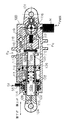
図1は本発明に係る航空機用脚昇降装置の第1実施例を示す図である。
図1において、20は金属等の高剛性素材で作られたボディである。ボディ20の一端には機体側への取付部21が形成され、ボディ20の略中央部付近から他端にかけて他端側に開口する第1室22と、第1室22の周囲の第2室23とが形成されている。
【0016】
第1室22には脚の取付部24を有するロッド25が挿入され、ロッド25の先端に設けられたピストン26によって第2室23が二つの室(以下、符号a、bを付して第2室23a、第2室23bと言う)に区画されていると共に、第1室22も二つの弁体27、28によって二つの室(以下、符号a、bを付して第1室22a、第1室22bと言う)に区画されている。弁体27、28はそれぞれスプリング29、30によって第1室22bの容積を減らす方向に付勢されており、また、第1室22aはロッド25に設けられた空気孔31によって外界に開放している。
【0017】
第1室22bは、孔32、通路33、リストリクタ34及び通路35を介してボディ20の他端側に設けられた第3室36に連通する。また、孔37及び通路38を介して第2室23bとリリースポートPaにも連通し、孔37、通路38及び第4室39を介してガスポートPbにも連通し、孔37、通路38、第4室39及び通路40を介して可変吐出量型ベーンポンプ(以下、単にポンプと言う)41の第1吐出ポート42にも連通し、孔32及び通路43を介してポンプ41の第2吐出ポート44にも連通し、通路45、フィルタ46及び通路47を介してポンプ室41のドレンポート48にも連通している。ポンプ41の第1吐出ポート42と第2吐出ポート44は、ポンプ41の回転方向に応じて一方が吐出側、他方が吸い込み側になる。ここでは説明の都合上、ポンプ41が反時計周りに回転する場合に、第1吐出ポート42が“吐出側”、第2吐出ポート44が“吸い込み側”になるものとする。なお、Mはポンプ41を駆動するためのモータ、VPWR はモータMの電源である。
【0018】
孔32及び孔37には第1シャトルバルブ49が装着されており、さらに、第4室39にも第2シャトルバルブ50が装着されている。第1シャトルバルブ49は、孔32及び孔37の間隔よりも若干長めのシャフトで二つの弁体を連結したもので、二つの弁体に加わる圧力の差に応じて往復動し、孔32及び孔37の一方を閉じ、他方を開くというものである。例えば、図示の状態(孔32が開き、孔37が閉じられている)は、通路38の圧力が高い場合である。第2シャトルバルブ50も形状が異なるものの第1シャトルバルブ49と類似の働きをする。すなわち、第2シャトルバルブ50は、スプリング51に規制されながら第4室39の内部を移動可能で、ガスポートPbと通路40(ポンプ41の第1吐出ポート42につながる通路)の圧力差に応じて一方を開き、他方を閉じるというものである。例えば、図示の状態(通路40が開き、ガスポートPbが閉じられている)は、通路40の圧力が高い場合である。
【0019】
ボディ20の他端側に設けられた第3室36には、メカニカルロック機構と称される機構が内蔵されている。この機構は、ボディ20を貫通してロッド25の外周面に当接する摩擦部材52の押し出し量(言い換えれば当接力)を弁体53の位置で調節するというものである。弁体53の位置は、通路35を介して導入される作動油の圧力とスプリング54の付勢力との釣り合いで決まる。作動油の圧力がゼロか又は相当に小さい時は図示位置にある。弁体53の摩擦部材52に当たる部分が斜めにカットされており、弁体53がスプリング54に付勢されて図面の右方向に位置するほど、摩擦部材52が大きく押し出され、ロッド25の外周面に強く圧接される。そして、ロッド25が最伸張位置になったとき、摩擦部材52がロッド25に形成された溝(図示略)に係合し、この位置でロッド25がロックされるようになっている。
【0020】
したがって、このメカニカルロック機構によれば、通路35を介して作動油を導入しない場合は、弁体53が図示の位置になって摩擦部材52がロッド25の溝に係合するから、ロッド25の伸縮を規制できる。一方、通路35を介して作動油を導入した場合は、スプリング54の付勢力に抗して弁体53が図面の左方向にスライドするから、摩擦部材52の係合を解除すると共に圧接力を軽減してロッド25の伸縮を許容できる。なお、ロッド25の伸縮を許容した場合は、通路35と第2室23aの間が連通すると共に、センサ55から信号Saが出力されるようになっている。
【0021】
このような構成において、第1室22b、第2室23a、第2室23b、第3室36及びポンプ41並びにこれらに連通する各通路を作動油で満たした状態で、モータMの電源VPWR を一極性にすると、モータMは一方向に回転し、ポンプ41も同方向に回転する。ここで、回転方向を時計周り方向とすると、前記想定より、ポンプ41の第1吐出ポート42が“吸い込み側”、第2吐出ポート44が“吐出側”になるため、第1シャトルバルブ49が図面の下方向に移動して孔37を開き、第1室22bの作動油が孔37、通路38、第4室39、通路40及び第1吐出ポート42を介してポンプ41に吸い込まれ、ポンプ41で加圧された後、第2吐出ポート44、通路43、通路33、リストラクタ34及び通路35を介して第3室36に吐出される。
【0022】
したがって、第3室36のメカニカルロック機構が作動し、ロッド25の移動が許容されると共に、第2室23aに高圧作動油が導入される結果、第2室23aの圧力が上昇し、ロッド25のピストン26が図面の右方向に移動して脚上げが行われる。脚上げの完了は、図2に示すアップロックシリンダ10の動きで検知される。なお、図2のアップロックシリンダ10は、ロック解除時に油圧を必要とするタイプのものである。
【0023】
一方、モータMの電源VPWR を他極性にすると、モータMは他方向に回転し、ポンプ41も同方向(反時計周り方向)に回転する。前記想定より、反時計周り方向に回転するポンプ41は第2吐出ポート44が“吸い込み側”、第1吐出ポート42が“吐出側”になる。このため、第1シャトルバルブ49が図示位置になって孔32が開かれ、第1室22bの作動油が孔32、通路43及び第2吐出ポート44を介してポンプ41に吸い込まれ、ポンプ41で加圧された後、第1吐出ポート42、通路40、第4室39及び通路38を介して第2室23bとリリースポートPaに吐出される。
【0024】
したがって、リリースポートPaに接続されたアップロックシリンダ10のロックが解除されると共に、第2室23bの圧力上昇に伴ってロッド25のピストン26が図面の左方向に移動する結果、脚下げが行われる。
油圧失陥、例えば、モータMやポンプ41が故障すると、もはや有効な油圧は得られない。かかる故障が飛行中に発生した場合、脚下げが不能になるが、本第1実施例の構成によれば、ガスポートPbに高圧ガスを印加するだけで、油圧失陥時の緊急脚下げを行うことができる。
【0025】
すなわち、ガスポートPbに高圧ガスを印加すれば、油圧失陥時にはガスポートPbの圧力が勝るから、第2シャトルバルブ50が図面の右方向に移動し、図外のガスボンベ(図2のガスボンベ13参照)からの高圧ガスを第4室39及び通路38を介してリリースポートPaと第2室23bに導入でき、この高圧ガスによってアップロックシリンダ10のロックを解除できると共に、第2室23bの(高圧ガスによる)圧力上昇に伴ってロッド25のピストン26を図面の左方向に移動させることができ、緊急脚下げを支障なく行うことができる。
【0026】
図2は本第1実施例の航空機用脚昇降装置を含む一例系統図である。10はアップロックシリンダ(但し、油圧導入によってロック状態を解除するタイプのもの)、13はガスボンベ、14は緊急脚下げ弁である。緊急脚下げ弁14は、緊急時以外は図示位置(ポートa−b間を遮断する位置)にあるが、電磁操作または手動操作により、ポートa−b間を連通する位置に切り換えることができるものである。
【0027】
図示のように、緊急脚下げ弁14のポートaをガスボンベ13に接続すると共に、同ポートbを脚ごとに設けられた本第1実施例の航空機用脚昇降装置(ハッチング部分)のガスポートPbに接続し、且つ、同装置のリリースポートPaをアップロックシリンダ10に接続しておけば、通常の脚上げ及び脚下げはもちろんのこと、緊急脚下げも支障なく行うことができる。
【0028】
しかも、本第1実施例の航空機用脚昇降装置は、油圧源としてのポンプ41やポンプ41を駆動するモータMなどの主要構成部品をボディ20に一体化したので、全体を一つのユニットとして取り扱うことができる。したがって、配管等を削減してレイアウト容易性を向上できるうえ、部品点数の減少に伴ってMTBFを改善できるという、特に小型航空機の分野にとって格別有益な効果が得られる。
【0029】
図3は本発明に係る航空機用脚昇降装置の第2実施例を示す図である。
図3において、60は金属等の高剛性素材で作られたボディである。ボディ60の一端には機体側への取付部61が形成され、ボディ60の略中央部付近から他端にかけて、他端側に開口する第1室62と、第1室62の周囲の第2室63とが形成されている。第1室62には脚の取付部64を有するロッド65が挿入され、ロッド65の先端に設けられたピストン66によって第2室63が二つの室(第2室63a、第2室63b)に区画されていると共に、第1室62もピストン67によって二つの室(第1室62a、第1室62b)に区画されている。ピストン67はスプリング68によって第1室62bの容積を減らす方向に付勢されており、また、第1室62aはロッド65に設けられた空気孔69によって外界に開放している。
【0030】
第1室62bは、ダンプバルブ70が図示位置にあるとき、通路71及び通路72を介して第3室73に連通する。第3室73は、孔74、アップロック電磁弁R、通路75、リストリクタ76及び通路77を介してボディ60の他端側に設けられた第4室78に連通する。第4室78には、第1実施例と同様なメカニカルロック機構が設けられており、さらに、第4室78は、スプリング79及びピストン80からなるアキュムレータ81(温度変化による圧力低下やわずかな外部もれによる圧力低下を補償して脚上げの際の不本意な脚下げ現象を防止するためのもの)を経てアップロックポートPcに連通している。また、第3室73は、孔82及び通路83を介して、第1実施例と同様な可変吐出量型ベーンポンプ(以下、単にポンプと言う)84の第1吐出ポート85にも連通しさらに、通路86及び通路87を介して第2室63bにも連通している。なお、通路86及び通路87は、ダンプバルブ70の位置にかかわらず連通しているが、ダンプバルブ70が矢印F方向に引かれると、通路71及び通路72とも連通するようになっている。
【0031】
また、第3室73は、ダンプバルブ70が矢印F方向に引かれると、通路88及び通路89を介して通路75に連通し、さらに、第3室73は、孔74及び通路90を介してポンプ84の第2吐出ポート91に連通している。
なお、ポンプ84の第1吐出ポート85と第2吐出ポート91は、ポンプ84の回転方向に応じて一方が吐出側、他方が吸い込み側になるものであり、第1実施例と同様に、ポンプ84が反時計周りに回転した場合に第1吐出ポート85が“吐出側”、第2吐出ポート91が“吸い込み側”になるものとする。
【0032】
第3室73には、シャトルバルブ92が装着されている。このシャトルバルブ92は、孔74及び孔82の間隔よりも若干長めのシャフトで二つの弁体を連結したもので、二つの弁体に加わる圧力の差に応じて往復動し、孔74及び孔82の一方を閉じ、他方を開くというものである。例えば、図示の状態(孔74が開き、孔82が閉じられている)は、通路83の圧力が高い場合である。
【0033】
このような構成において、第1室62b、第2室63b、第3室73及びポンプ84並びにこれらに連通する各通路を作動油で満たした状態で、モータMの電源VPWR を一極性にすると、モータMは一方向に回転し、ポンプ84も同方向に回転する。ここで、回転方向を時計周り方向とすると、前記想定より、ポンプ84の第1吐出ポート85が“吸い込み側”、第2吐出ポート91が“吐出側”になるため、シャトルバルブ92が図面の下方向に移動して孔82を開き、第1室62bの作動油が通路71、通路72、第3室73、孔82、通路83及び第1吐出ポート85を介してポンプ84に吸い込まれ、ポンプ84で加圧された後、第2吐出ポート91から通路90へと吐出されるが、アップロック電磁弁R(この電磁弁は脚上げ下げ時にオンとなって図示位置になる)が図示位置であれば、結局、通路75、リストラクタ76及び通路77を介して第4室78、アキュムレータ81及びアップロックポートPcに吐出される。
【0034】
したがって、第4室78のメカニカルロック機構が作動し、ロッド65の移動が許容されると共に、第2室63aに高圧作動油が導入される結果、第2室63aの圧力が上昇し、ロッド65のピストン66が図面の右方向に移動して脚上げが行われる。脚上げの完了は、図4に示すアップロックシリンダ10の動きで検知される。なお、図4のアップロックシリンダ10は、ロック状態の保持に油圧を必要とするタイプのものである。
【0035】
一方、モータMの電源VPWR を他極性にすると、モータMは他方向に回転し、ポンプ84も同方向(反時計周り方向)に回転する。前記想定より、反時計周り方向に回転するポンプ84は第2吐出ポート91が“吸い込み側”、第1吐出ポート85が“吐出側”になる。このため、シャトルバルブ92が図示位置になって孔74が開かれ、第1室62bの作動油が通路71、通路72、第3室73、孔74、通路90及び第2吐出ポート91を介してポンプ84に吸い込まれ、ポンプ84で加圧された後、第1吐出ポート85、通路83、通路86及び通路87を介して第2室63bに吐出される。
【0036】
したがって、アップロックポートPcの圧力が下がってアップロックシリンダ10のロックが解除されると共に、第2室63bの圧力上昇に伴ってロッド65のピストン66が図面の左方向に移動する結果、脚下げが行われる。
油圧失陥時にはダンプバルブ70を矢印F方向に引く。通路89と第4室73の間が連通すると共に、通路71、通路72、通路86及び通路87の間も連通し、結局、第2室62a、62bと第3室63bの間の作動油の移動がフリーになるから、脚部の自重を利用(脚部の自由落下)した緊急脚下げを行うことができる。
【0037】
図4は第2実施例の航空機用脚昇降装置を含む一例系統図であり、10はアップロックシリンダ(但し、ロック状態の保持を油圧力で行うタイプのもの)である。脚昇降装置(ハッチング部分)のアップロックポートPcをアップロックシリンダ10に接続するだけよく、きわめて構成を簡素化できる。
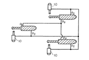
図5は本発明に係る航空機用脚昇降装置の第3実施例を示す図である。
【0038】
図5において、100は金属等の高剛性素材で作られたボディである。ボディ100の一端には機体側への取付部101が形成され、ボディ100の略中央部付近から他端にかけて、他端側に開口する第1室102と、第1室102の周囲の第2室103とが形成されている。第1室102には脚の取付部104を有するロッド105が挿入され、ロッド105の先端に設けられたピストン106によって第2室103が二つの室(第2室103a、第2室103b)に区画されていると共に、第1室102もピストン107によって二つの室(第1室102a、第1室102b)に区画されている。ピストン107はスプリング108によって第1室102bの容積を減らす方向に付勢されており、また、第1室102aはロッド105に設けられた空気孔109によって外界に開放している。
【0039】
第1室102bは、孔110を介して第1ポートPeに連通している。また、第1室102bは、孔110、通路111、リストリクタ112及び通路113を介してボディ100の他端側に設けられた第3室114(第1実施例と同様なメカニカルロック機構を有する)にも連通し、孔115を介して第2室103b、第2ポートPd及び可変吐出量型ベーンポンプ(以下、単にポンプと言う)116の第1吐出ポート117にも連通し、孔110及び通路118を介してポンプ116の第2吐出ポート119にも連通している。なお、ポンプ116の第1吐出ポート117と第2吐出ポート119は、ポンプ116の回転方向に応じて一方が吐出側、他方が吸い込み側になるものであり、第1、2実施例と同様に、ポンプ116が反時計周りに回転した場合に第1吐出ポート117が“吐出側”、第2吐出ポート119が“吸い込み側”になるものとする。
【0040】
孔110及び孔115にはシャトルバルブ120が装着されている。このシャトルバルブ120は、孔110及び孔115の間隔よりも若干長めのシャフトで二つの弁体を連結したもので、二つの弁体に加わる圧力の差に応じて往復動し、孔110及び孔115の一方を閉じ、他方を開くというものである。例えば、図示の状態(孔110が開き、孔115が閉じられている)は、第2ポートPdの圧力が高い場合である。
【0041】
このような構成において、第1室102b、第2室103a、第2室103b及びポンプ116並びにこれらに連通する各通路を作動油で満たした状態で、モータMの電源VPWR を一極性にすると、モータMは一方向に回転し、ポンプ116も同方向に回転する。ここで、回転方向を時計周り方向とすると、前記想定より、ポンプ116の第1吐出ポート117が“吸い込み側”、第2吐出ポート119が“吐出側”になるため、シャトルバルブ120が図面の下方向に移動して孔115を開き、第1室102bの作動油が孔115及び第1吐出ポート117を介してポンプ116に吸い込まれ、ポンプ116で加圧された後、第2吐出ポート119及び通路118を介して第1ポートPe(用途は後述)に吐出されると共に、通路111、リストラクタ112及び通路113を介して第3室114に吐出される。
【0042】
したがって、第3室114のメカニカルロック機構が作動し、ロッド105の移動が許容されると共に、第2室103aに高圧作動油が導入される結果、第2室103aの圧力が上昇し、ロッド105のピストン106が図面の右方向に移動して脚上げが行われる。脚上げの完了は、図6に示すアップロックシリンダ10の動きで検知される。なお、図6のアップロックシリンダ10は、ロック解除時に油圧を必要とするタイプ(第1実施例と同じタイプ)のものである。
【0043】
一方、モータMの電源VPWR を他極性にすると、モータMは他方向に回転し、ポンプ116も同方向(反時計周り方向)に回転する。前記想定より、反時計周り方向に回転するポンプ116は第2吐出ポート119が“吸い込み側”、第1吐出ポート117が“吐出側”になる。このため、シャトルバルブ120が図示位置になって孔110が開かれ、第1室102bの作動油が孔110、通路118及び第2吐出ポート119を介してポンプ116に吸い込まれ、ポンプ116で加圧された後、第1吐出ポート117から第2ポートPd(用途は後述)と第2室103bに吐出される。したがって、図6に示すように、第2ポートPdにアップロックシリンダ10を接続しておけば、第2ポートPdの圧力上昇に伴ってロックが解除されると共に、第2室103bの圧力上昇に伴ってロッド105のピストン106が図面の左方向に移動する結果、脚下げが行われる。
【0044】
油圧失陥対策は、図6に示すように、脚ごとに設けられた本第3実施例の航空機用脚昇降装置の第1ポートPe同士と第2ポートPd同士を接続する。こうすると、一つの脚昇降装置に油圧失陥(例えばポンプ116やモータMの故障)が生じても、他の脚昇降装置の第2ポートPdからの加圧作動油によって、第3室114のメカニカルロック機構のロックが支障なく解除される上、シャトルバルブ120が図面下方に移動して第1室102bと第2室103bとの間が連通し、脚部の自重による緊急脚下げを行うことができる。
【0045】
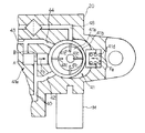
図7はポンプ(可変吐出量型ベーンポンプ)を含む要部の構成図である。なお、図7では第1実施例の構成を示しているが、これは代表例であり、他の実施例についても共通する。
図7において、ポンプ41は、モータMによって回転駆動されるロータ41aと、このロータ41aに対して所定の範囲で偏心するリング41bと、リング41bに取り付けられた多数のベーン41cとを有する公知の可変吐出量型ベーンポンプであり、ベーン41cとリング41bで作られる容積がロータ41aの回転(すなわちモータMの回転)と共に変化することにより、作動油の吸入・吐出を行うものである。可変吐出量型ベーンポンプの吸入・吐出量(以下、吐出量で代表)は、モータMの回転数に加え、リング41bの偏心量によっても変化する。図示のリング41bの偏心量は現在最大であり、モータMの回転数を無視すればこの状態のときに最大の吐出量が得られる。リング41bの偏心量は、図面の右側に設けられたスプリング41dの付勢力Faと、図面の左側に設けられた複合ピストン41eの押圧力Fbとの釣り合いで決まり、最大の偏心量はFa>Fbの場合である。
【0046】
ここで、スプリング41dと共に“圧力コンペンセータ(圧力補償機構)”を構成する図示の複合ピストン41eは、二つのピストンA、Bをシャフトで連結しているように見えるが、これは作図上の都合である。実際は二つのピストンA、Bはつながっておらず、それぞれが独立してFbを発生するようになっている。このことは、通路40に圧力が発生した場合を考えると容易に理解できる。もし、二つのピストンA、Bがシャフトでつながっていた場合、通路40に圧力が発生してもピストンA、Bの各受圧面に働く圧力が逆向きとなって打ち消されてしまい、複合ピストン41eは動かない。
【0047】
図示の複合ピストン41eの機能は要するに、押圧力Fbの大きさを、ポンプ41の第1吐出ポート44(通路43)の圧力に対応させると共に、ポンプ41の第2吐出ポート42(通路40)の圧力にも対応させる点にある。このような機能を満たすための構成は、例えば、▲1▼ピストンAは第1吐出ポート44の圧力が上がると図面の右方向に移動する、▲2▼ピストンBは第2吐出ポート42の圧力が上がると図面の右方向に移動する、▲3▼ピストンA、Bはそれぞれ個別にリング41bを押圧する、ようになっていればよい。
【0048】
かかる特徴的な構成を有する圧力コンペンセータを備えた上記各実施例のポンプ(可変吐出量型ベーンポンプ)は、第1吐出ポート44と第2吐出ポート42の各圧力に応じて偏心量を変化させるので、ピストンA、Bの受圧面積を調節することにより、第1吐出ポート44の圧力と第2吐出ポート42の圧力を個別に設定できる。このため、ピストン26の二つの受圧面(第2室23aに臨む面と第2室23bに臨む面)の面積差に伴う第2室23aと第2室23bの不本意な圧力差を吸収できるばかりか、外部負荷(脚の自重など)の大きさも考慮した最適な圧力設定を行うことができるという格別な効果が得られる。
【0049】
また、上記各実施例のモータMに“DCモータ”を用いると好ましい。DCモータは負荷が大きくなると回転数が低下する特性があり、一方、可変吐出量型ベーンポンプも回転数が低下すると吐出量が減る特性があり、両者の特性が相まって負荷に対する吐出量の制御応答性が向上するからである。このことは、モータMの小型化や圧力コンペンセータの簡素化が可能なことを意味し、したがって、脚昇降装置のユニット化に寄与する有益な効果が得られる。
【0050】
なお、上記第1実施例における第1室22内に設けられた弁体28は、通常は、スプリング30によって図面の右方向に付勢されており、弁体27に着座して一体化しているが、第1室22bの圧力がスプリング30の付勢力を越えて大きくなった場合に弁体27から離座して第1室22bと第1室22aの間を連通するようになっている。この作用は油圧失陥時に必要である。すなわち、第1実施例においては、油圧失陥時にガスポートPbから高圧ガスを導入し、第4室39及び通路38を介して第2室23bに加えるが、反対側の第2室23aは通路35〜孔32を介して第1室22bに連通しているため、この第1室22bの圧力の逃げ道を作っておかなければ、いくら第2室23bの圧力をガスの力で高めてもピストン26がスムーズに動かず、その結果、緊急脚下げに支障をきたすからである。
【0051】
また、上記第2実施例のアキュムレータ81と電磁弁Rは、同実施例における特徴的な構成要素の一つである。上記第2実施例の説明から理解されるように、アキュムレータ81は通路77、第4室78、第2室63a及びアップロックポートPcに接続されており、電磁弁Rが閉じられているときにこれら各部の圧力変動(温度変化による圧力低下やリークによる圧力低下など)を補償するものである。したがって、仮に、アップロックポートPcを閉鎖しておけば、通路77、第4室78及び第2室63aの圧力を高圧に保持できるから、アップロックシリンダ(図4符号10参照)を用いなくても、脚上げ状態を保持することができ、より一層構成を簡素化できるから好ましい。
【0052】
また、上記第3実施例の系統図(図6)によれば、油圧システムを多重化(三つの脚部の場合、三重化)でき、一つの脚昇降装置の油圧システムが故障した場合でも他の二つの脚昇降装置の油圧システムでバックアップできるから、特にスペースの関係で多重化が困難な小型機の安全性を格段に向上できる点で有益である。
【0053】
【発明の効果】
本発明によれば、緊急脚下げを含む脚昇降機構をユニット化でき、レイアウト容易性とMTBFの改善を図ることができる。
本発明によれば、ポンプ効率がよく、モータの小型化を図ることができる。
【0054】
本発明によれば、二つの吐出ポートの圧力に応じてポンプの吐出量を制御でき、ロッドが伸びるときと縮むときのそれぞれに適した圧力設定を行うことができる。
本発明によれば、アキュムレータによって一方の室の圧力を維持でき、脚上げ状態を保持できるため、敢えて外部にロックアップシリンダを設ける必要がなくなり、構成を一層簡素化できる。
【0055】
本発明によれば、油圧システムを多重化してシステムの安全性を高めることができる。
【図面の簡単な説明】
【図1】第1実施例の構成図である。
【図2】第1実施例の系統図である。
【図3】第2実施例の構成図である。
【図4】第2実施例の系統図である。
【図5】第3実施例の構成図である。
【図6】第3実施例の系統図である。
【図7】各実施例に共通の要部構成図である。
【図8】従来の構成図(ガス圧バックアップ方式)である。
【図9】従来の構成図(ダンプバルブバックアップ方式)である。
【符号の説明】
M:モータ
20:ボディ
25:ロッド
41:ポンプ[0001]
BACKGROUND OF THE INVENTION
The present invention relates to an aircraft leg lifting apparatus, and more particularly to a leg lifting apparatus suitable for use in a small aircraft.
In general, aircraft legs (referred to as legs including wheels, wheels, and arms) are often stored in wings and fuselage during flight. This is because they are used only during take-off and landing, and air resistance adversely affects flight performance (speed and cruising range).
[0002]
[Prior art]
8 and 9 are system diagrams of conventionally known aircraft leg lifting devices. These two conventional examples are common in that the hydraulic pressure is used for the power for raising and lowering the legs, and are different in an emergency leg lowering method when the hydraulic pressure is lost.
First, the common points will be described. In FIGS. 8 and 9, the hydraulic oil in the reservoir 1 is pressurized by an engine-driven pump 2 (two units are assumed to be a twin engine for convenience), and then filtered. 3, it is supplied to the
[0003]
The
[0004]
According to this, when the leg elevating electromagnetic valve 4 is switched from the illustrated position to the communication position between the ports ad and cb, pressurized hydraulic fluid is introduced into the ports a of the three
[0005]
By the way, in an aircraft leg lifting device, the function of emergency leg lowering at the time of hydraulic failure is indispensable. The
[0006]
On the other hand, the
[0007]
In general, the former (FIG. 8) emergency leg lowering mechanism is called a “gas pressure backup system”, and the latter (FIG. 9) emergency leg lowering mechanism is called a “dump valve backup system”.
[0008]
[Problems to be solved by the invention]
However, as can be understood from the drawings (FIGS. 8 and 9), the above two conventional techniques have a problem that many components are required and the complexity of the configuration cannot be denied. That is, a
[0009]
SUMMARY OF THE INVENTION Accordingly, an object of the present invention is to unitize a leg lifting mechanism including emergency leg lowering, thereby improving layout ease and MTBF.
[0010]
[Means for Solving the Problems]
Book The invention includes, in a common body, a pump as a hydraulic pressure source, a motor that drives the pump, a rod that expands and contracts by receiving the discharge pressure of the pump, and a mechanical lock mechanism that restricts the expansion and contraction of the rod. It is implemented.
According to this, since the leg raising / lowering mechanism including the emergency leg lowering is unitized, the layout can be easily improved and the MTBF can be improved.
[0011]
Book Invention ,Previous Pump itself Is a variable capacity type.
According to this, the pump efficiency is good and the motor can be miniaturized.
Book Invention ,Previous The pump is of a variable capacity type having two discharge ports, one of which serves as a discharge side and the other serves as a suction side according to the direction of rotation, and each of the two discharge ports communicates with two chambers. The rod is expanded and contracted by a pressure difference between the two chambers, and further includes a pressure compensator for controlling the discharge amount of the pump according to the respective pressures of the two discharge ports.
[0012]
According to this, since the discharge amount of the pump can be controlled according to the pressures of the two discharge ports, it is possible to perform pressure setting suitable for each of when the rod is extended and when the rod is contracted.
Book Invention ,Previous An accumulator is connected to one of the two chambers that has a high pressure when the legs are raised, and an electromagnetic valve that connects and disconnects between the accumulator and the one chamber and a hydraulic pressure source is provided. Features.
[0013]
According to this, since the pressure in one chamber can be maintained by the accumulator and the leg-raised state can be maintained, there is no need to dare to provide a lockup cylinder outside, and the configuration can be further simplified.
Book Invention ,Previous An output port for outputting the discharge pressure of the pump to another aircraft leg lifting device is provided.
[0014]
According to this, the safety of the system can be improved by multiplexing the hydraulic system.
[0015]
DETAILED DESCRIPTION OF THE INVENTION
Embodiments of the present invention will be described below with reference to the drawings.
FIG. 1 is a view showing a first embodiment of an aircraft leg lifting apparatus according to the present invention.
In FIG. 1, 20 is a body made of a highly rigid material such as metal. A
[0016]
A rod 25 having a
[0017]
The first chamber 22 b communicates with a third chamber 36 provided on the other end side of the
[0018]
A first shuttle valve 49 is attached to the holes 32 and 37, and a second shuttle valve 50 is also attached to the
[0019]
A mechanism called a mechanical lock mechanism is incorporated in the third chamber 36 provided on the other end side of the
[0020]
Therefore, according to this mechanical lock mechanism, when hydraulic oil is not introduced through the
[0021]
In such a configuration, the first chamber 22b, the second chamber 23a, the second chamber 23b, the third chamber 36, the
[0022]
Accordingly, the mechanical lock mechanism of the third chamber 36 is operated, the movement of the rod 25 is allowed, and the high pressure hydraulic oil is introduced into the second chamber 23a. As a result, the pressure in the second chamber 23a increases, and the rod 25 The
[0023]
On the other hand, when the power source VPWR of the motor M is set to another polarity, the motor M rotates in the other direction, and the
[0024]
Therefore, the lock of the
If a hydraulic pressure failure occurs, for example, if the motor M or the
[0025]
That is, if a high-pressure gas is applied to the gas port Pb, the pressure of the gas port Pb prevails when the hydraulic pressure is lost, so the second shuttle valve 50 moves to the right in the drawing, and the gas cylinder (not shown in FIG. 2) The high pressure gas from (see) can be introduced into the release port Pa and the second chamber 23b through the
[0026]
FIG. 2 is an example system diagram including the aircraft leg lifting apparatus of the first embodiment.
[0027]
As shown in the figure, the port a of the emergency
[0028]
In addition, the aircraft leg lifting apparatus of the first embodiment integrates the main components such as the
[0029]
FIG. 3 is a view showing a second embodiment of the aircraft leg lifting apparatus according to the present invention.
In FIG. 3, 60 is a body made of a highly rigid material such as metal. A
[0030]
The first chamber 62b communicates with the
[0031]
Further, when the
Note that one of the
[0032]
A
[0033]
In such a configuration, when the first chamber 62b, the second chamber 63b, the
[0034]
Accordingly, the mechanical lock mechanism of the
[0035]
On the other hand, when the power VPWR of the motor M is set to another polarity, the motor M rotates in the other direction, and the
[0036]
Accordingly, the pressure of the up-lock port Pc decreases, the lock of the up-
When the hydraulic pressure fails, the
[0037]
FIG. 4 is an example system diagram including the aircraft leg lifting apparatus according to the second embodiment, and
FIG. 5 is a view showing a third embodiment of the aircraft leg lifting apparatus according to the present invention.
[0038]
In FIG. 5,
[0039]
The
[0040]
A shuttle valve 120 is attached to the
[0041]
In such a configuration, when the
[0042]
Therefore, the mechanical lock mechanism of the third chamber 114 is operated, the
[0043]
On the other hand, when the power VPWR of the motor M is set to another polarity, the motor M rotates in the other direction, and the
[0044]
As shown in FIG. 6, the hydraulic failure failure countermeasure connects the first ports Pe and the second ports Pd of the aircraft leg lifting apparatus of the third embodiment provided for each leg. In this way, even if hydraulic failure (for example, failure of the
[0045]
FIG. 7 is a configuration diagram of a main part including a pump (variable discharge type vane pump). Although FIG. 7 shows the configuration of the first embodiment, this is a representative example and is common to other embodiments.
In FIG. 7, the
[0046]
Here, the
[0047]
The function of the
[0048]
The pumps (variable discharge amount type vane pumps) of the above-described embodiments each having the pressure compensator having such a characteristic configuration change the amount of eccentricity according to the pressures of the
[0049]
In addition, it is preferable to use a “DC motor” for the motor M of each of the above embodiments. The DC motor has the characteristic that the rotational speed decreases when the load increases. On the other hand, the variable discharge vane pump also has the characteristic that the discharge quantity decreases when the rotational speed decreases. This is because it improves. This means that the motor M can be reduced in size and the pressure compensator can be simplified. Therefore, a beneficial effect contributing to unitization of the leg lifting device can be obtained.
[0050]
The valve body 28 provided in the first chamber 22 in the first embodiment is normally urged to the right in the drawing by a
[0051]
Further, the accumulator 81 and the electromagnetic valve R of the second embodiment are one of characteristic components in the embodiment. As can be understood from the description of the second embodiment, the accumulator 81 is connected to the passage 77, the
[0052]
Further, according to the system diagram of the third embodiment (FIG. 6), the hydraulic system can be multiplexed (in the case of three legs, triple), even if the hydraulic system of one leg lifting device fails. This is advantageous in that the safety of a small machine that is difficult to be multiplexed due to space can be greatly improved.
[0053]
【The invention's effect】
Book According to the invention, the leg lifting mechanism including the emergency leg lowering can be unitized, and the layout can be easily improved and the MTBF can be improved.
Book According to the invention, the pump efficiency is good and the motor can be miniaturized.
[0054]
Book According to the invention, it is possible to control the discharge amount of the pump according to the pressures of the two discharge ports, and it is possible to perform pressure setting suitable for each of when the rod extends and contracts.
Book According to the invention, the pressure in one chamber can be maintained by the accumulator, and the leg-raised state can be maintained, so that it is not necessary to provide a lock-up cylinder outside, and the configuration can be further simplified.
[0055]
Book According to the invention, the safety of the system can be enhanced by multiplexing the hydraulic system.
[Brief description of the drawings]
FIG. 1 is a configuration diagram of a first embodiment.
FIG. 2 is a system diagram of the first embodiment.
FIG. 3 is a configuration diagram of a second embodiment.
FIG. 4 is a system diagram of a second embodiment.
FIG. 5 is a configuration diagram of a third embodiment.
FIG. 6 is a system diagram of a third embodiment.
FIG. 7 is a configuration diagram showing a main part common to the embodiments.
FIG. 8 is a conventional configuration diagram (gas pressure backup method).
FIG. 9 is a conventional configuration diagram (dump valve backup method).
[Explanation of symbols]
M: Motor
20: Body
25: Rod
41: Pump
Claims (2)
前記ポンプを、回転方向に応じて一方が吐出側他方が吸い込み側として働く二つの吐出ポートを有する可変容量型にし、且つ、該二つの吐出ポートのそれぞれを二つの室に連通すると共に、該二つの室の圧力差で前記ロッドを伸縮させるように構成し、さらに、該二つの吐出ポートのそれぞれの圧力に応じて前記ポンプの吐出量を制御する圧力コンペンセータを備え、
前記二つの室のうち脚上げ状態のときに高圧となる一方の室にアキュムレータを接続し、且つ、該アキュムレータ及び該一方の室と油圧発生源との間を断接する電磁弁を備えたことを特徴とする航空機用脚昇降装置。 In a common body, a pump as a hydraulic pressure source, a motor that drives the pump, a rod that expands and contracts by receiving the discharge pressure of the pump, and a mechanical lock mechanism that restricts the expansion and contraction of the rod are mounted ,
The pump is of a variable capacity type having two discharge ports, one of which serves as the discharge side and the other serves as the suction side according to the direction of rotation, and each of the two discharge ports communicates with the two chambers. The rod is expanded and contracted by a pressure difference between two chambers, and further includes a pressure compensator that controls the discharge amount of the pump according to the pressure of each of the two discharge ports,
An accumulator is connected to one of the two chambers that is at a high pressure when the legs are raised, and an electromagnetic valve is provided to connect and disconnect the accumulator and the one chamber to a hydraulic pressure generation source. An aircraft leg lifting device.
Priority Applications (4)
| Application Number | Priority Date | Filing Date | Title |
|---|---|---|---|
| JP21608297A JP3671198B2 (en) | 1997-06-13 | 1997-08-11 | Aircraft leg lifting device |
| US09/094,485 US6059228A (en) | 1997-06-13 | 1998-06-10 | Hydraulic system |
| DE69819600T DE69819600T2 (en) | 1997-06-13 | 1998-06-10 | Hydraulic system for an aircraft landing gear |
| EP98304589A EP0884239B1 (en) | 1997-06-13 | 1998-06-10 | Hydraulic system for an aircraft landing gear |
Applications Claiming Priority (3)
| Application Number | Priority Date | Filing Date | Title |
|---|---|---|---|
| JP9-156631 | 1997-06-13 | ||
| JP15663197 | 1997-06-13 | ||
| JP21608297A JP3671198B2 (en) | 1997-06-13 | 1997-08-11 | Aircraft leg lifting device |
Publications (2)
| Publication Number | Publication Date |
|---|---|
| JPH1159592A JPH1159592A (en) | 1999-03-02 |
| JP3671198B2 true JP3671198B2 (en) | 2005-07-13 |
Family
ID=26484324
Family Applications (1)
| Application Number | Title | Priority Date | Filing Date |
|---|---|---|---|
| JP21608297A Expired - Fee Related JP3671198B2 (en) | 1997-06-13 | 1997-08-11 | Aircraft leg lifting device |
Country Status (4)
| Country | Link |
|---|---|
| US (1) | US6059228A (en) |
| EP (1) | EP0884239B1 (en) |
| JP (1) | JP3671198B2 (en) |
| DE (1) | DE69819600T2 (en) |
Families Citing this family (32)
| Publication number | Priority date | Publication date | Assignee | Title |
|---|---|---|---|---|
| JP4426711B2 (en) * | 2000-09-01 | 2010-03-03 | 株式会社ショーワ | Tilt device for ship propulsion equipment |
| WO2004066326A2 (en) * | 2003-01-17 | 2004-08-05 | The Regents Of The University Of California | Electro-thermally actuated lateral contact microrelay and associated manufacturing process |
| US6832540B2 (en) * | 2003-03-17 | 2004-12-21 | Kenneth E. Hart | Locking hydraulic actuator |
| US6948685B2 (en) | 2003-10-27 | 2005-09-27 | Hr Textron, Inc. | Locking device with solenoid release pin |
| US7216581B2 (en) * | 2004-01-16 | 2007-05-15 | The Boeing Company | Piston locking actuator |
| JP4240514B2 (en) | 2004-02-24 | 2009-03-18 | 本田技研工業株式会社 | Direct acting actuator |
| CA2479454A1 (en) * | 2004-08-30 | 2006-02-28 | Gary Stephen Ataman | Internally locking actuator with direct acting integral lock sensor |
| US7195197B2 (en) * | 2005-02-11 | 2007-03-27 | Hr Textron, Inc. | Techniques for controlling a fin with unlimited adjustment and no backlash |
| US7350751B2 (en) * | 2005-04-08 | 2008-04-01 | Icon Aviation, Inc. | Anti-flip landing gear for aircraft |
| US7249458B2 (en) * | 2005-07-22 | 2007-07-31 | Ashradn Holdings Ltd. | Self-contained hydraulic actuator system |
| FR2907097B1 (en) * | 2006-10-17 | 2009-01-16 | Messier Bugatti Sa | HYDRAULIC SYSTEM ARCHITECTURE OF AIRCRAFT AIRBORNE MANEUVER |
| FR2907096B1 (en) * | 2006-10-17 | 2009-01-16 | Messier Bugatti Sa | HYDRAULIC SYSTEM ARCHITECTURE OF AIRCRAFT AIRBORNE MANEUVER |
| US8109465B1 (en) | 2007-08-02 | 2012-02-07 | Textron Innovations Inc. | Electro-magnetic up-lock for retractable landing gear |
| FR2922190B1 (en) | 2007-10-11 | 2010-04-09 | Eurocopter France | RETRACTION CYLINDER, GYRO AERIAL LIGHTER PROVIDED WITH SUCH A RETRACTION CYLINDER |
| JP2010127456A (en) | 2008-12-01 | 2010-06-10 | Nabtesco Corp | Electric actuator |
| JP5306838B2 (en) | 2008-12-26 | 2013-10-02 | ナブテスコ株式会社 | Electric actuator |
| GB2469484B (en) * | 2009-04-15 | 2013-09-18 | Ge Aviat Systems Ltd | Landing gear actuation control system |
| FR2982240B1 (en) * | 2011-11-09 | 2013-12-13 | Messier Bugatti Dowty | METHOD FOR DEPLOYING AIRCRAFT AIRCRAFT LIGHTERS IN EMERGENCY MODE. |
| CN102530244B (en) * | 2012-02-14 | 2014-04-09 | 南京航空航天大学 | All-electric retractable actuator cylinder suitable for laying landing gear down emergently and operating mode thereof |
| JP6170755B2 (en) * | 2013-06-18 | 2017-07-26 | 住友精密工業株式会社 | Electric hydraulic actuator |
| CN103466083B (en) * | 2013-08-30 | 2015-12-02 | 中航飞机起落架有限责任公司 | A kind of emergent pressurized strut |
| US10214283B2 (en) | 2013-09-12 | 2019-02-26 | E.B. Robinson Ltd. | Aircraft landing gear and method |
| US20160025199A1 (en) * | 2014-07-25 | 2016-01-28 | Triumph Actuation Systems - Connecticut, LLC, d/b/a Triumph Aerospace Systems - Seattle | Ball screw actuator with internal locking |
| CN104354854B (en) * | 2014-10-29 | 2016-06-29 | 中航飞机起落架有限责任公司 | A kind of multi-functional undercarriage brace apparatus |
| CN104454723B (en) * | 2014-11-05 | 2016-06-01 | 中航飞机起落架有限责任公司 | A kind of landing gear strut pressurized strut function control valve |
| CA2895679C (en) | 2015-06-26 | 2017-12-12 | V-Bond Lee | Dual locking hydraulic actuator for structural brace |
| EP3109487A1 (en) | 2015-06-26 | 2016-12-28 | SPP Canada Aircraft, Inc. | Dual locking hydraulic actuator for structural brace |
| EP3248869B1 (en) * | 2016-05-25 | 2018-09-12 | AIRBUS HELICOPTERS DEUTSCHLAND GmbH | Retraction / extension of a landing gear in an aircraft |
| EP3324055B1 (en) * | 2016-11-21 | 2019-07-03 | Airbus Operations GmbH | A hydraulic actuator |
| CN106314766B (en) * | 2016-11-25 | 2018-06-01 | 中航飞机起落架有限责任公司 | A kind of undercarriage actuating cylinder control lock |
| US10787247B2 (en) | 2018-01-16 | 2020-09-29 | Goodrich Corporation | Hybrid actuator |
| CN110345129B (en) * | 2019-07-19 | 2020-09-11 | 浙江雷宸智能科技有限公司 | Hydraulic cylinder |
Family Cites Families (10)
| Publication number | Priority date | Publication date | Assignee | Title |
|---|---|---|---|---|
| US2331108A (en) * | 1940-07-10 | 1943-10-05 | Reconstruction Finance Corp | Hydraulic mechanism |
| US2892626A (en) * | 1955-08-17 | 1959-06-30 | Cleveland Pneumatic Ind Inc | Landing gear construction |
| US2975595A (en) * | 1958-02-06 | 1961-03-21 | Chromalloy Corp | Pressure-operated systems with ignitable propellants |
| US3107886A (en) * | 1961-11-09 | 1963-10-22 | Kaman Aircraft Corp | Hydraulic system for aircraft landing gear and hydraulic actuator therefor |
| US4634082A (en) * | 1983-05-10 | 1987-01-06 | Menasco Inc. | Extendable shock strut |
| FR2554415B1 (en) * | 1983-11-09 | 1986-02-07 | Messier Hispano Sa | LANDERS FOR AIRCRAFT, ESPECIALLY FOR HELICOPTERS |
| JPH01141905U (en) * | 1988-03-23 | 1989-09-28 | ||
| US5144801A (en) * | 1989-04-28 | 1992-09-08 | Parker Hannifin Corporation | Electro-hydraulic actuator system |
| US5184465A (en) * | 1990-09-28 | 1993-02-09 | The Boeing Company | Landing gear drag strut actuator having self-contained pressure charge for emergency use |
| JP2964607B2 (en) * | 1990-10-11 | 1999-10-18 | 日産自動車株式会社 | Hydraulic supply device |
-
1997
- 1997-08-11 JP JP21608297A patent/JP3671198B2/en not_active Expired - Fee Related
-
1998
- 1998-06-10 DE DE69819600T patent/DE69819600T2/en not_active Expired - Lifetime
- 1998-06-10 US US09/094,485 patent/US6059228A/en not_active Expired - Lifetime
- 1998-06-10 EP EP98304589A patent/EP0884239B1/en not_active Expired - Lifetime
Also Published As
| Publication number | Publication date |
|---|---|
| JPH1159592A (en) | 1999-03-02 |
| US6059228A (en) | 2000-05-09 |
| EP0884239A2 (en) | 1998-12-16 |
| DE69819600T2 (en) | 2004-09-30 |
| EP0884239B1 (en) | 2003-11-12 |
| DE69819600D1 (en) | 2003-12-18 |
| EP0884239A3 (en) | 2001-03-21 |
Similar Documents
| Publication | Publication Date | Title |
|---|---|---|
| JP3671198B2 (en) | Aircraft leg lifting device | |
| EP2253847B1 (en) | Variable capacity lubricant vane pump | |
| KR101753419B1 (en) | Lubricant pump system | |
| US8256576B2 (en) | On-demand lubrication system for improved flow management and containment | |
| EP3112698B1 (en) | Electro hydrostatic actuators | |
| EP1319836A2 (en) | Digital controlled fluid translating device | |
| CA2507233C (en) | Augmenting flight control surface actuation system and method | |
| US4667472A (en) | Electric integrated actuator with variable gain hydraulic output | |
| WO2007087704A1 (en) | Variable displacement variable pressure vane pump system | |
| US20220033069A1 (en) | Aircraft assembly | |
| US6796526B2 (en) | Augmenting flight control surface actuation system and method | |
| US5575150A (en) | Stiffness enhanced electrohydrostatic actuator | |
| JP2001526335A (en) | Hydraulic control for mobile work machines, especially wheel loaders, for damping longitudinal vibrations | |
| EP2878816B1 (en) | Pump control device | |
| US4953639A (en) | Closed loop hydraulic drill feed system | |
| JP2018094969A (en) | Eha system of aircraft landing gear | |
| US10539131B2 (en) | Electro hydrostatic actuator | |
| JP4712701B2 (en) | Hydraulic pressure controller | |
| US5572918A (en) | Multi-functional valve | |
| JPS6327561B2 (en) | ||
| EP1694968A1 (en) | Apparatus and methods for actuation | |
| WO2018011975A1 (en) | Electro hydrostatic actuator system | |
| JPH0578685B2 (en) | ||
| JPH0261638B2 (en) | ||
| JP2669202B2 (en) | Industrial vehicle hydraulics |
Legal Events
| Date | Code | Title | Description |
|---|---|---|---|
| A131 | Notification of reasons for refusal |
Free format text: JAPANESE INTERMEDIATE CODE: A131 Effective date: 20040608 |
|
| A521 | Written amendment |
Free format text: JAPANESE INTERMEDIATE CODE: A523 Effective date: 20040623 |
|
| TRDD | Decision of grant or rejection written | ||
| A711 | Notification of change in applicant |
Free format text: JAPANESE INTERMEDIATE CODE: A712 Effective date: 20041015 |
|
| A01 | Written decision to grant a patent or to grant a registration (utility model) |
Free format text: JAPANESE INTERMEDIATE CODE: A01 Effective date: 20041019 |
|
| A61 | First payment of annual fees (during grant procedure) |
Free format text: JAPANESE INTERMEDIATE CODE: A61 Effective date: 20041021 |
|
| R150 | Certificate of patent or registration of utility model |
Free format text: JAPANESE INTERMEDIATE CODE: R150 |
|
| TRDD | Decision of grant or rejection written | ||
| A01 | Written decision to grant a patent or to grant a registration (utility model) |
Free format text: JAPANESE INTERMEDIATE CODE: A01 Effective date: 20050301 |
|
| A61 | First payment of annual fees (during grant procedure) |
Free format text: JAPANESE INTERMEDIATE CODE: A61 Effective date: 20050302 |
|
| R150 | Certificate of patent or registration of utility model |
Free format text: JAPANESE INTERMEDIATE CODE: R150 |
|
| FPAY | Renewal fee payment (event date is renewal date of database) |
Free format text: PAYMENT UNTIL: 20080428 Year of fee payment: 3 |
|
| FPAY | Renewal fee payment (event date is renewal date of database) |
Free format text: PAYMENT UNTIL: 20090428 Year of fee payment: 4 |
|
| FPAY | Renewal fee payment (event date is renewal date of database) |
Free format text: PAYMENT UNTIL: 20100428 Year of fee payment: 5 |
|
| FPAY | Renewal fee payment (event date is renewal date of database) |
Free format text: PAYMENT UNTIL: 20100428 Year of fee payment: 5 |
|
| FPAY | Renewal fee payment (event date is renewal date of database) |
Free format text: PAYMENT UNTIL: 20110428 Year of fee payment: 6 |
|
| FPAY | Renewal fee payment (event date is renewal date of database) |
Free format text: PAYMENT UNTIL: 20120428 Year of fee payment: 7 |
|
| FPAY | Renewal fee payment (event date is renewal date of database) |
Free format text: PAYMENT UNTIL: 20120428 Year of fee payment: 7 |
|
| FPAY | Renewal fee payment (event date is renewal date of database) |
Free format text: PAYMENT UNTIL: 20130428 Year of fee payment: 8 |
|
| FPAY | Renewal fee payment (event date is renewal date of database) |
Free format text: PAYMENT UNTIL: 20130428 Year of fee payment: 8 |
|
| S531 | Written request for registration of change of domicile |
Free format text: JAPANESE INTERMEDIATE CODE: R313531 |
|
| FPAY | Renewal fee payment (event date is renewal date of database) |
Free format text: PAYMENT UNTIL: 20130428 Year of fee payment: 8 |
|
| R350 | Written notification of registration of transfer |
Free format text: JAPANESE INTERMEDIATE CODE: R350 |
|
| FPAY | Renewal fee payment (event date is renewal date of database) |
Free format text: PAYMENT UNTIL: 20130428 Year of fee payment: 8 |
|
| FPAY | Renewal fee payment (event date is renewal date of database) |
Free format text: PAYMENT UNTIL: 20140428 Year of fee payment: 9 |
|
| R250 | Receipt of annual fees |
Free format text: JAPANESE INTERMEDIATE CODE: R250 |
|
| LAPS | Cancellation because of no payment of annual fees |