JP3671136B2 - Power steering device - Google Patents
Power steering device Download PDFInfo
- Publication number
- JP3671136B2 JP3671136B2 JP2000177353A JP2000177353A JP3671136B2 JP 3671136 B2 JP3671136 B2 JP 3671136B2 JP 2000177353 A JP2000177353 A JP 2000177353A JP 2000177353 A JP2000177353 A JP 2000177353A JP 3671136 B2 JP3671136 B2 JP 3671136B2
- Authority
- JP
- Japan
- Prior art keywords
- motor
- steering
- current
- electric motor
- value
- Prior art date
- Legal status (The legal status is an assumption and is not a legal conclusion. Google has not performed a legal analysis and makes no representation as to the accuracy of the status listed.)
- Expired - Fee Related
Links
Images


Description
【0001】
【発明の属する技術分野】
本発明は、電動モータにより駆動されるポンプの発生油圧によりステアリング機構に操舵補助力を与えるパワーステアリング装置に関する。
【0002】
【従来の技術】
ステアリング機構に結合されたパワーシリンダにオイルポンプからの作動油を供給することによって、ステアリングホイールの操作を補助するパワーステアリング装置が知られている。オイルポンプは、たとえば、直流モータからなる電動モータによって駆動され、その回転速度に応じた操舵補助力がパワーシリンダから発生される。
【0003】
電動モータの駆動制御は、たとえば、ステアリングホイールの舵角速度に基づいて行われる。すなわち、ステアリングホイールに関連して設けられた舵角センサの出力に基づいて舵角速度が求められ、この舵角速度に基づいて電動モータの目標回転速度が設定される。この目標回転速度が達成されるように、電動モータに電圧が供給される。さらに具体的には、舵角速度が極めて小さい場合には、ステアリングホイールの操作がわずかであるから、操舵補助が不要であるとみなされ、電動モータが停止される。一方、舵角速度が大きければ、ステアリングホイールが大きく操作されていると見なされ、そのときの舵角速度に応じて電動モータが駆動され、操舵補助力が発生される。
【0004】
車両が車幅方向に傾斜を有する直線道路を走行している場合には、車両を安定させるためには、ステアリングホイールにトルクを加えて一定の舵角で保持する必要がある。したがって、舵角速度のみに基づいて電動モータの停止制御を行うと、上記のような場合に操舵補助が行われないから、操舵フィーリングが悪くなるおそれがある。
そこで、従来では、舵角速度が所定の舵角速度しきい値以下であって、かつ、電動モータに流れるモータ電流が所定の電流しきい値以下である状態が一定時間にわたって継続することを条件に、電動モータを停止するようにしている(たとえば、WO99/08922参照)。
【0005】
ステアリングホイールにトルクが加えられていると、電動モータに負荷がかかるから、目標回転速度を達成するために、電動モータの負荷電流が増大する。すなわち、モータ電流は、ステアリングホイールに加えられるトルクに対応している。上述の従来技術は、この点に着目し、モータ電流が電流しきい値以下であることを、電動モータを停止する際の必要条件としている。
【0006】
【発明が解決しようとする課題】
電動モータは、車両に搭載されたバッテリからの給電を受けて作動する。この車載バッテリは、発生電圧(バッテリ電圧)が必ずしも安定していない。とくに、バッテリ電圧が低下すると、電動モータの停止制御に不具合が生じる。
すなわち、バッテリ電圧が低下すると、電動モータへの供給電力が減少し、電動モータの回転速度が低下する。そこで、電動モータを制御するコントローラは、目標回転速度を達成するために、バッテリ電圧の低下による電力不足分を、モータ電流を増加させて補おうとする。その結果、電動モータの負荷が小さいときにも、モータ電流が大きな値をとることになる。
【0007】
したがって、無負荷状態であっても、モータ電流が電流しきい値以下とならなくなり、電動モータを停止させることができなくなる。これにより、電力が無駄に消費されてしまう。
そこで、この発明の目的は、上述の技術的課題を解決し、電源電圧の変動によらずに電動モータの停止または減速制御を良好に行うことができるパワーステアリング装置を提供することである。
【0008】
【課題を解決するための手段および発明の効果】
上記の目的を達成するための請求項1記載の発明は、電動モータ(27)により駆動されるポンプ(26)の発生油圧によって操舵補助力を発生させるパワーステアリング装置において、上記電動モータに電力を供給する電源(40)の電圧(VB)を検出する電源電圧検出手段(30,S12)と、上記電動モータに流れるモータ電流の値を検出するための電流検出手段(12,S11)と、上記電源電圧検出手段によって検出された電源電圧に基づいて、上記電動モータを停止または所定のアイドル回転速度(Ri)に減速するときのモータ電流値に関するしきい値である電流しきい値(Istop)を可変設定する電流しきい値設定手段(30,S13)と、上記電流検出手段により検出されたモータ電流値が上記電流しきい値設定手段によって設定された電流しきい値以下である状態が所定時間にわたって継続したことを条件に、上記電動モータを停止させるか、または、上記電動モータを上記アイドル回転速度に減速するモータ制御手段(30,S14,S16,S17)とを含み、上記電流しきい値設定手段は、上記電源電圧検出手段によって検出された電源電圧が低いほど上記電流しきい値を大きく設定するものであることを特徴とするパワーステアリング装置である。括弧内の英数字は、後述の実施形態における対応構成要素等の符号を表す。以下、この項において同じ。
【0009】
この発明によれば、電源電圧の変動に応じて電流しきい値が可変設定される。具体的には、電源電圧が低いほど電流しきい値が大きく設定される。そして、モータ電流値がこの可変設定される電流しきい値以下となることが、電動モータを停止またはアイドル回転速度に減速させるための必要条件となっている。
したがって、電源電圧が変動しても、電動モータに対する負荷が小さい状態となると、モータ電流値が確実に電流しきい値以下となる。とくに、電源電圧が低下したときに、電動モータを目標回転速度で回転させるためにモータ電流値が大きくなった場合であっても、モータ電流値を電流しきい値以下の値とすることができる。これにより、確実に、電動モータを停止または減速させることができる。
【0010】
これにより、無駄な電力消費を省くことができ、パワーステアリング装置の省エネルギー性を向上することができる。
【0011】
電動モータのモータ電流値は、その負荷、すなわち操舵トルクに応じて変化する。したがって、モータ電流値が操舵補助が不要な操舵トルク範囲に相当する電流しきい値以下の値を有する状態が一定時間継続したことを条件に電動モータを停止または減速することとすれば、操舵トルクが小さいときに電動モータを停止または減速させることができる。
請求項2記載の発明は、舵角速度を検出するための舵角速度検出手段(11,30,S1)をさらに含み、上記モータ制御手段は、上記舵角速度検出手段により検出された舵角速度が所定の舵角速度しきい値(Vb)以下であって、かつ、上記電流検出手段により検出されたモータ電流値が上記電流しきい値設定手段によって設定された電流しきい値以下である状態が所定時間にわたって継続したことを条件に、上記電動モータを停止させるか、または、上記電動モータを上記アイドル回転速度に減速するものである(30,S10,S14,S16,S17)ことを特徴とする請求項1記載のパワーステアリング装置である。
【0012】
この発明では、舵角速度に関する条件が付加されているので、電動モータの停止または減速制御をより適切に行うことができる。
【0013】
【発明の実施の形態】
以下では、この発明の実施の形態を、添付図面を参照して詳細に説明する。
図1は、本発明の一実施形態に係るパワーステアリング装置の基本的な構成を示す概念図である。このパワーステアリング装置は、車両のステアリング機構1に関連して設けられ、このステアリング機構1に操舵補助力を与えるためのものである。
【0014】
ステアリング機構1は、ドライバによって操作されるステアリングホイール2と、このステアリングホイール2に連結されたステアリング軸3と、ステアリング軸3の先端に設けられたピニオンギア4と、ピニオンギア4に噛合するラックギア部5aを有し、車両の左右方向に延びたラック軸5とを備えている。ラック軸5の両端にはタイロッド6がそれぞれ結合されており、このタイロッド6は、それぞれ、操舵輪としての前左右輪FL、FRを支持するナックルアーム7に結合されている。ナックルアーム7は、キングピン8まわりに回動可能に設けられている。
【0015】
この構成により、ステアリングホイール2が操作されてステアリング軸3が回転されると、この回転がピニオンギア4およびラック軸5によって車両の左右方向に沿う直線運動に変換される。この直線運動は、ナックルアーム7のキングピン8まわりの回動に変換され、これによって、前左右輪FL、FRの転舵が達成される。
ステアリング軸3には、ステアリングホイール2に加えられた操舵トルクの方向および大きさに応じてねじれを生じるトーションバー9と、トーションバー9のねじれの方向および大きさに応じて開度が変化する油圧制御弁23とが組み込まれている。油圧制御弁23は、ステアリング機構1に操舵補助力を与えるパワーシリンダ20に接続されている。パワーシリンダ20は、ラック軸5に一体的に設けられたピストン21と、ピストン21によって区画された一対のシリンダ室20a、20bとを有しており、シリンダ室20a、20bは、それぞれ、オイル供給/帰還路22a、22bを介して、油圧制御弁23に接続されている。
【0016】
油圧制御弁23は、さらに、リザーバタンク25およびオイルポンプ26を通るオイル循環路24の途中部に介装されている。オイルポンプ26は、電動式のモータ27によって駆動され、リザーバタンク25に貯留されている作動油を汲み出して油圧制御弁23に供給する。余剰分の作動油は、油圧制御弁23からオイル循環路24を介してリザーバタンク25に帰還される。
油圧制御弁23は、トーションバー9に一方方向のねじれが加わった場合には、オイル供給/帰還路22a、22bのうちの一方を介してパワーシリンダ20のシリンダ室20a、20bのうちの一方に作動油を供給する。また、トーションバー9に他方方向のねじれが加えられた場合には、オイル供給/帰還路22a、22bのうちの他方を介してシリンダ室20a、20bのうちの他方に作動油を供給する。トーションバー9にねじれがほとんど加わっていない場合には、油圧制御弁23は、いわば平衡状態となり、作動油はパワーシリンダ20に供給されることなく、オイル循環路24を循環する。
【0017】
パワーシリンダ20のいずれかのシリンダ室に作動油が供給されると、ピストン21が車幅方向に沿って移動する。これにより、ラック軸5に操舵補助力が作用することになる。
油圧制御弁に関連する構成例は、たとえば、特開昭59−118577号公報に詳しく開示されている。
電動モータ27は、たとえば直流モータからなり、駆動回路28を介して、電子制御ユニット30によって制御される。駆動回路28は、たとえば、パワートランジスタのブリッジ回路からなり、電源としての車載バッテリ40からの電力を、電子制御ユニット30から与えられる制御信号に応じて電動モータ27に供給する。
【0018】
電子制御ユニット30は、車載バッテリ40からの電力供給を受けて動作するマイクロコンピュータを含み、このマイクロコンピュータは、CPU31と、CPU31のワークエリアなどを提供するRAM32と、CPU31の動作プログラムを記憶したROM33と、CPU31、RAM32およびROM33を相互接続するバス34とを備えている。CPU31は、制御周期毎に車載バッテリ40の発生電圧(以下「バッテリ電圧」という。)VBを検出する。
【0019】
電子制御ユニット30には、舵角センサ11から出力される舵角データが与えられるようになっている。舵角センサ11は、ステアリングホイール2に関連して設けられており、イグニッションキースイッチが導通されてエンジンが始動したときのステアリングホイール2の舵角を初期値「0」として、この初期値からの相対舵角に対応し、かつ操舵方向に応じた符号の舵角データを出力する。CPU31は、この舵角データに基づいて、車両が直進状態のときの舵角である舵角中点を求め、さらに、この舵角中点と舵角センサ11が出力する舵角データとに基づいて、車輪FR,FLの方向に対応した絶対舵角θを求める。舵角中点の検出は、たとえば、舵角センサ11から出力される舵角データをサンプリングし、舵角データの値のヒストグラムを作成し、所定のサンプリング数のデータが収集された後に最頻出舵角データを舵角中点の舵角データとして求めることにより達成される。
【0020】
電子制御ユニット30には、さらに、電動モータ27に流れる電流を検出する電流検出回路12からの電流データが与えられるようになっている。電流データは、電動モータ27の消費電流値(モータ電流)に比例した値を有する。
さらに、電子制御ユニット30には、車速センサ13から出力される車速データが与えられるようになっている。車速センサ13は、車両の速度Vfを直接的に検出するものでもよく、また、車輪に関連して設けられた車輪速センサの出力パルスに基づいて車両の速度Vfを計算により求めるものであってもよい。
【0021】
電子制御ユニット30は、舵角センサ11、電流検出回路12および車速センサ13からそれぞれ与えられる舵角データ、電流データおよび車速データに基づいて、電動モータ27の駆動を制御する。
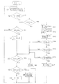
図2は、電動モータ27の駆動制御を説明するためのフローチャートであり、図3は、舵角速度とモータ回転速度との対応関係を示す特性図である。CPU31は、舵角センサ11から出力される舵角データに基づいて、ステアリングホイール2の舵角の時間変化率である舵角速度Vθおよび車両の速度Vfを求める(ステップS1)。その後、CPU31は、電動モータ27が停止しているか否かを判断する(ステップS2)。この判断は、たとえば、電動モータ27が起動されたときにセットされ、電動モータ27が停止されたときにリセットされるフラグを用いて行うことができる。
【0022】
電動モータ27が停止していれば(ステップS2のYES)、CPU31は、電動モータ27を起動すべきか否かを調べるために、上記求められた舵角速度Vθが所定の起動しきい値Va(たとえばVa=5(degree/sec))以上であるか否かを判断する(ステップS3)。舵角速度Vθが起動しきい値Va未満であれば(ステップS3のNO)、プログラムはステップS1に戻る。舵角速度Vθが起動しきい値Va以上であれば(ステップS3のYES)、CPU31は、電動モータ27を起動する(ステップS4)。この場合、CPU31は、上記求められた舵角速度Vθの値に基づいてモータ回転速度Rを決定する。
【0023】
CPU31は、モータ回転速度Rの決定に際し、舵角速度Vθが所定の第1しきい値VT1(たとえばVT1=10(degree/sec))以下であるか否かを判断する(ステップS5)。舵角速度Vθが第1しきい値VT1以下であれば(ステップS5のYES)、モータ回転速度Rが所定の第1回転速度R1(たとえばR1=1800(rpm) )になるように、電動モータ27を駆動する(ステップS6)。すなわち、舵角速度Vθが起動しきい値Va以上で、かつ第1しきい値VT1以下であれば、電動モータ27は、舵角速度Vθの値によらずに、一定の第1回転速度R1で駆動される。
【0024】
舵角速度Vθが第1しきい値VT1を超えている場合には(ステップS5のNO)、CPU31は、舵角速度Vθが第1しきい値VT1よりも大きな第2しきい値VT2(たとえばVT2=600(degree/sec) )未満であるか否かを判断する(ステップS7)。舵角速度Vθが第2しきい値VT2未満であれば(ステップS7のYES)、CPU31は、舵角速度Vθの値に応じたモータ回転速度Rで電動モータ27を駆動する(ステップS8)。すなわち、舵角速度Vθが第1しきい値VT1よりも大きく、かつ、第2しきい値VT2未満である領域では、CPU31は、舵角速度Vθに対してモータ回転速度Rが第1回転速度R1と第2回転速度R2(R2>R1)との間でほぼリニアに変化するように、モータ回転速度Rを決定する。
【0025】
舵角速度Vθが第2しきい値VT2以上であるならば(ステップS7のNO)、CPU31は、モータ回転速度Rが所定の第2回転速度R2(たとえばR2=6000(rpm) )になるように、電動モータ27を駆動する(ステップS9)。すなわち、舵角速度Vθが第2しきい値VT2以上であれば、電動モータ27は、舵角速度Vθの値によらずに、一定の第2回転速度R2で駆動される。
図3に示されているように、第2しきい値VT2は、車速域に応じて可変設定される。すなわち、車両の速度Vfが大きいほど、第2しきい値VT2は大きな値に設定される。これにより、車両の速度Vfが大きいほどモータ回転速度Rが小さく設定されることになり、操舵補助力が小さくなる。こうして、車両の速度Vfに応じた適切な操舵補助力を発生するための車速感応制御が行われる。
【0026】
ステップS2において、電動モータ27が駆動されていると判断されれば、CPU31は、舵角速度Vθが所定の停止しきい値(第2所定値)Vb(たとえばVb=8(degree/sec))以下であるか否かを判断する(ステップS10)。舵角速度Vθが停止しきい値Vbを超えていれば(ステップS10のNO)、プログラムはステップS5に移行し、CPU31は、求められた舵角速度Vθの値に基づいてモータ回転速度Rを決定し、この決定されたモータ回転速度Rで電動モータ27を駆動する。
【0027】
舵角速度Vθが停止しきい値Vb(舵角しきい値)以下であれば(ステップS10のYES)、CPU31は、電流検出回路12から出力される電流データに基づいてモータ電流値Imを求める(ステップS11)。さらに、CPU31は、最新のバッテリ電圧VBを検出し(ステップS12)、この検出されたバッテリ電圧VBおよび車速センサ13によって検出される車速Vfに基づいて、モータ停止判定電流値Istop(電流しきい値)を求める(ステップS13)。そして、CPU31は、この求められたモータ電流値Imがモータ停止判定電流値Istop以下か否かを判断する(ステップS14)。
【0028】
モータ停止判定電流値Istopは、操舵補助が不要な状態のときのモータ電流の上限値である。このモータ停止判定電流値Istopは、モータ停止電流初期値Istop(0)に対して、バッテリ電圧VBおよび車速Vfに基づく補正を加えることによって求められる。モータ停止電流初期値Istop(0)は、後述するモータ停止電流初期値演算処理によって定められる。
モータ電流値Imがモータ停止判定電流値Istop以下の値を有するならば(ステップS13のYES)、CPU31は、さらに、上述のようにして検出される絶対舵角θが、舵角中点付近の停止可能範囲Δθ内(たとえば、舵角中点を中心とした±3度程度の範囲)の値かどうかを調べる(ステップS15)。この判断が肯定されると、CPU31は、舵角速度Vθが停止しきい値Vb以下であって、モータ電流値Imがモータ停止判定電流値Istop以下であり、かつ、絶対舵角θが停止可能範囲Δθの範囲内の値である状態が一定時間(たとえば1〜3秒)継続したか否かを判断する(ステップS16)。この判断が肯定されれば(ステップS16のYES)、ステアリングホイール2はほとんど操舵されていないと考えることができるから、CPU31は、電動モータ27を停止させる(ステップS17)。一方、上記ステップS10,S14〜S16の判断のいずれかが否定されれば、CPU31は、ステップS5からの処理を行ってモータ回転速度Rを求め、その回転速度で電動モータ27を駆動する。
【0029】
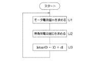
図4は、モータ停止電流初期値Istop(0)の演算処理を説明するためのフローチャートである。CPU31は、ステアリングホイール2に加えられる操舵トルクTに応じてモータ電流値Imが変化することを利用し、モータ電流値Imを常時モニタする(ステップU1)。このモータ電流値Imに基づいて、CPU31は、電動モータ27が無負荷状態である場合のモータ電流値である無負荷電流値I0を求める(ステップU2)。そして、この求められた無負荷電流値I0に、車両の仕様に応じて予め定められた所定値dIを加算した値I0+dIをモータ停止電流初期値Istop(0)として設定する。
【0030】
図5は、操舵トルクTとモータ電流値Imとの対応関係を示す特性図である。横軸に操舵トルクTがとられ、縦軸にモータ電流値Imがとられている。モータ電流値Imは、操舵トルクTが0の付近では、T=0の点を頂点とする曲線で表すことができる。操舵トルクTが0の場合には電動モータ27は無負荷状態であるから、モータ電流値Imの極小値が無負荷電流値I0に対応する。
一方、ステアリングホイール2に対して操舵補助力を与える必要のないトルクの範囲は、車両の仕様により定まる。このトルク範囲が、0を中心にトルクしきい値T1、−T1によって挟まれた範囲である場合、これらのトルクしきい値T1、−T1に対応するモータ電流値と無負荷電流値I0との差が予め求められて上記所定値dIとして設定される。そして、無負荷電流値I0に所定値dIを加算した値I0+dI(=Istop(0))以下の範囲を、ステアリングホイール2が操舵されていない範囲と判断することができる。上記所定値dIは、たとえば車種ごとに予め求められてROM33に格納されている。
【0031】
無負荷電流値I0は、主として作動油の温度によって変動する。すなわち、たとえば作動油の温度が低い場合には、作動油の粘性は高いから、作動油の温度が高い場合に比べて電動モータ27の負荷は大きくなる。したがって、モータ電流値Imは、作動油の温度が低い場合には大きな値をとる。つまり、図5のIm−T曲線は、上方にスライドし、無負荷電流値I0も大きくなる。
そこで、この実施形態では、無負荷電流値I0を演算により求め、求められた無負荷電流値I0にROM33に格納されている所定値dIを加算した値I0+dIが、モータ停止電流初期値Istop(0)として設定される。
【0032】
無負荷電流値I0の演算は、たとえば、サンプリングしたモータ電流値Imのうち最頻出電流値を求めることによって達成される。より具体的には、CPU31は、モータ回転速度Rが一定であることを条件として、電流検出回路12から出力される電流データを一定時間(たとえば10(min) 〜1(hour))にわたってサンプリングする。このサンプリングによって得られた電流データに基づいて求められるモータ電流値Imは、正規分布をなす。この場合、操舵トルクTが0の場合のモータ電流値Imが最頻出電流値となるから、この最頻出電流値を無負荷電流値I0として求める。
【0033】
このような演算以外に、たとえば、モータ回転速度Rが一定であることを条件として、一定時間または一定回数にわたってサンプリングされたモータ電流値Imの中から最小値を求め、この求められた最小値を無負荷電流値I0としてもよい。
図6は、図2のステップS13におけるモータ停止判定電流値Istopの演算処理を説明するための図である。図6(a)にはバッテリ電圧VBとモータ停止判定電流値Istopとの関係が示されており、図6(b)には車速Vfとモータ停止判定電流値Istopとの関係が示されている。より具体的には、モータ停止判定電流値Istopは、モータ停止電流初期値Istop(0)、バッテリ電圧VBおよび車速Vfの関数として定められる。
【0034】
図6(a)に示されているように、モータ停止判定電流値Istopは、バッテリ電圧VBが高いほど小さく設定され、バッテリ電圧VBが低いほど大きく設定される。電動モータ27は、その回転速度が設定回転速度Rに等しくなるようにフィードバック制御される。バッテリ電圧VBが低下すると、電動モータ27への供給電力が不足するから、電子制御ユニット30は、その不足分をモータ電流を増加させて補おうとする。その結果、ステアリングホイール2にトルクが加えられていない無負荷状態においても、モータ電流値Imが大きな値をとることになる。
【0035】
そこで、この実施形態では、バッテリ電圧VBが低下したときには、モータ停止判定電流値Istopを大きく設定することとしている。これにより、無負荷状態のときには、モータ電流値Imが大きな値をとる場合であっても、図2のステップS14において肯定的な判定がされることになり、電動モータ27の適切な停止制御を行える。これにより、無駄な電力消費を低減できるから、パワーステアリング装置の省エネルギー性を向上できる。
【0036】
一方、図6(b)に示されているように、車速Vfの増加に伴って、モータ停止判定電流値Istopは大きく設定される。高速走行時には、操舵補助はさほど必要にならない。そこで、この実施形態では、車速Vfが大きいときには、モータ停止判定電流値Istopを大きく設定することにより、電動モータ27を可能な限り停止状態とし、省エネルギー性の向上が図られている。
以上のようにこの第1実施形態によれば、バッテリ電圧VBの変動に応じてモータ停止判定電流値Istopが可変設定されるから、電動モータ27の停止制御を適切に行える。これにより、無駄なエネルギー消費を抑制できる。
【0037】
また、舵角速度Vθが第1しきい値VT1以下の領域では、舵角速度Vθとモータ回転速度Rとは、いわゆるヒステリシス特性を有している。すなわち、モータ起動のためのしきい値Vaは、モータ停止のためのしきい値Vbよりも小さくなっている。これにより、操舵が開始されたときには操舵補助力を速やかに発生させることができるとともに、操舵終了時には操舵補助を速やかに停止させることができる。これにより、操舵フィーリングの向上と省エネルギー性の向上とを併せて達成できる。
【0038】
図7は、この発明の第2の実施形態を説明するための図であり、舵角速度Vθとモータ回転速度Rとの関係が示されている。この図7の説明において、上述の図1および図2を再び参照する。
この実施形態では、無負荷状態においては、電動モータ27を停止させるのではなく、電動モータ27の回転速度Rをアイドル回転速度Ri(Ri<R1)に減速することとしている。すなわち、図2のステップS10,S14〜S16のすべての条件が成立したときに、電動モータ27を停止する代わりに、その回転速度をアイドル回転速度Riに減速する。
【0039】
この構成は、操舵補助が必要になったときに、電動モータ27の回転速度を速やかに立ち上げて必要な油圧を発生させることができるので、操舵補助の応答性に優れているという利点がある。この構成を採用することで、操舵補助が不要なときには、アイドル回転速度Riでの回転により省エネルギー化を図り、かつ、操舵補助が必要になったときには速やかな立ち上がりを実現できるので、操舵フィーリングを向上できる。
【0040】
そして、図2のステップS13の処理によって、バッテリ電圧VBの変動に応じて、モータ停止判定電流値Istopが適切に可変設定されるから、無負荷状態のときには、バッテリ電圧VBの変動によらずに、電動モータ27の回転をアイドル回転速度Riに減速することができる。
以上、本発明の実施の2つの形態について説明しているが、本発明は他の形態で実施することもできる。たとえば、上述の実施形態では、絶対舵角θが舵角中点付近の値であることを電動モータ27の停止またはアイドル回転速度Riへの減速のための必要条件としているが、この条件は省かれてもよい。その他、特許請求の範囲に記載された技術的事項の範囲で種々の設計変更を施すことが可能である。
【図面の簡単な説明】
【図1】本発明の第1実施形態に係るパワーステアリング装置の基本的な構成を示す概念図である。
【図2】モータの駆動制御を説明するためのフローチャートである。
【図3】舵角速度に対するモータ回転速度の設定例を示す特性図である。
【図4】モータ停止電流初期値設定処理を示すフローチャートである。
【図5】モータ停止電流初期値設定処理を説明するための図である。
【図6】モータ停止判定電流値の演算処理を説明するための図である。
【図7】本発明の第2実施形態における舵角速度とモータ回転速度との関係を示す特性図である。
【符号の説明】
1 ステアリング機構
2 ステアリングホイール
11 舵角センサ
12 電流検出回路
13 車速センサ
20 パワーシリンダ
23 油圧制御弁
26 オイルポンプ
27 電動モータ
28 駆動回路
30 電子制御ユニット
40 車載バッテリ[0001]
BACKGROUND OF THE INVENTION
The present invention relates to a power steering device that applies a steering assist force to a steering mechanism by hydraulic pressure generated by a pump driven by an electric motor.
[0002]
[Prior art]
There is known a power steering device that assists the operation of a steering wheel by supplying hydraulic oil from an oil pump to a power cylinder coupled to a steering mechanism. The oil pump is driven by, for example, an electric motor including a direct current motor, and a steering assist force corresponding to the rotation speed is generated from the power cylinder.
[0003]
The drive control of the electric motor is performed based on the steering angular speed of the steering wheel, for example. That is, the steering angular speed is obtained based on the output of the steering angle sensor provided in association with the steering wheel, and the target rotational speed of the electric motor is set based on the steering angular speed. A voltage is supplied to the electric motor so that this target rotational speed is achieved. More specifically, when the rudder angular velocity is extremely small, the steering wheel is operated slightly, so that it is considered that steering assistance is unnecessary, and the electric motor is stopped. On the other hand, if the rudder angular velocity is large, it is considered that the steering wheel is operated greatly, and the electric motor is driven according to the rudder angular velocity at that time, and a steering assist force is generated.
[0004]
When the vehicle is traveling on a straight road having an inclination in the vehicle width direction, in order to stabilize the vehicle, it is necessary to apply torque to the steering wheel and hold the steering wheel at a constant steering angle. Therefore, if the stop control of the electric motor is performed based only on the steering angular velocity, steering assistance is not performed in the above case, and the steering feeling may be deteriorated.
Therefore, conventionally, on the condition that the rudder angular speed is equal to or less than a predetermined rudder angular speed threshold value and the motor current flowing through the electric motor is equal to or smaller than the predetermined current threshold value, the condition continues for a certain period of time. The electric motor is stopped (for example, refer to WO99 / 08922).
[0005]
When torque is applied to the steering wheel, a load is applied to the electric motor, so that the load current of the electric motor increases in order to achieve the target rotational speed. That is, the motor current corresponds to the torque applied to the steering wheel. The above-described conventional technology pays attention to this point, and makes the motor current equal to or less than the current threshold value as a necessary condition for stopping the electric motor.
[0006]
[Problems to be solved by the invention]
The electric motor operates by receiving power from a battery mounted on the vehicle. In this vehicle battery, the generated voltage (battery voltage) is not always stable. In particular, when the battery voltage decreases, a malfunction occurs in the stop control of the electric motor.
That is, when the battery voltage decreases, the power supplied to the electric motor decreases and the rotation speed of the electric motor decreases. Therefore, the controller for controlling the electric motor, in order to achieve the target rotational speed, the power shortage due to a decrease in battery voltage, and attempt to compensate by increasing the motor current. As a result, even when the load of the electric motor is small, the motor current takes a large value.
[0007]
Therefore, even in the no-load state, the motor current does not become lower than the current threshold value, and the electric motor cannot be stopped. As a result, power is wasted.
SUMMARY OF THE INVENTION Accordingly, an object of the present invention is to solve the above technical problem and provide a power steering device capable of satisfactorily performing stop or deceleration control of an electric motor regardless of fluctuations in power supply voltage.
[0008]
[Means for Solving the Problems and Effects of the Invention]
In order to achieve the above object, the invention according to claim 1 is a power steering device for generating a steering assist force by the hydraulic pressure generated by the pump (26) driven by the electric motor (27), wherein electric power is supplied to the electric motor. Power supply voltage detection means (30, S12) for detecting the voltage (VB) of the power supply (40) to be supplied, current detection means (12, S11) for detecting the value of the motor current flowing through the electric motor, Based on the power supply voltage detected by the power supply voltage detection means, a current threshold value (Istop) that is a threshold value related to a motor current value when the electric motor is stopped or decelerated to a predetermined idle rotation speed (Ri) is set. The current threshold setting means (30, S13) for variably setting and the motor current value detected by the current detection means are obtained by the current threshold setting means. Motor control means (30) for stopping the electric motor or decelerating the electric motor to the idle rotation speed on condition that the state of being equal to or lower than the preset current threshold value has continued for a predetermined time. , S14, S16, S17) and only contains, the current threshold setting means, characterized in that the power supply voltage detected by the supply voltage detecting means is set large low as the current threshold This is a power steering device. Alphanumeric characters in parentheses indicate codes of corresponding components in the embodiments described later. The same applies hereinafter.
[0009]
According to the present invention, the current threshold value is variably set according to the fluctuation of the power supply voltage. Specifically, the current threshold is set larger as the power supply voltage is lower. The motor current value being equal to or less than the variably set current threshold is a necessary condition for stopping or decelerating the electric motor to the idle rotation speed.
Therefore, even if the power supply voltage fluctuates, if the load on the electric motor becomes small, the motor current value is reliably below the current threshold value . In particular, when the power supply voltage is lowered, even if the motor current value increases to rotate the electric motor at the target rotational speed, the motor current value can be set to a value equal to or less than the current threshold value. . Thereby , an electric motor can be stopped or decelerated reliably.
[0010]
Thereby, useless power consumption can be omitted and the energy saving performance of the power steering apparatus can be improved .
[0011]
The motor current value of the electric motor changes according to the load, that is, the steering torque. Therefore, if the electric motor is stopped or decelerated on the condition that the state in which the motor current value has a value equal to or less than the current threshold value corresponding to the steering torque range that does not require steering assistance continues for a certain period of time, the steering torque When the motor is small, the electric motor can be stopped or decelerated.
The invention according to claim 2 further includes a rudder angular velocity detecting means (11, 30, S1) for detecting a rudder angular speed, wherein the motor control means has a predetermined rudder angular speed detected by the rudder angular speed detecting means. A state in which the motor current value detected by the current detection means is equal to or less than the current threshold set by the current threshold setting means over a predetermined time. 2. The electric motor is stopped on the condition that the operation is continued, or the electric motor is decelerated to the idle rotation speed (30, S10, S14, S16, S17). It is a power steering device of description.
[0012]
In this invention, since the condition regarding the steering angular speed is added, the electric motor can be stopped or decelerated more appropriately.
[0013]
DETAILED DESCRIPTION OF THE INVENTION
Hereinafter, embodiments of the present invention will be described in detail with reference to the accompanying drawings.
FIG. 1 is a conceptual diagram showing a basic configuration of a power steering apparatus according to an embodiment of the present invention. This power steering device is provided in association with the steering mechanism 1 of the vehicle, and is for applying a steering assist force to the steering mechanism 1.
[0014]
The steering mechanism 1 includes a steering wheel 2 operated by a driver, a
[0015]
With this configuration, when the steering wheel 2 is operated and the
The steering
[0016]
The
When the
[0017]
When hydraulic oil is supplied to any cylinder chamber of the
A configuration example related to the hydraulic control valve is disclosed in detail in, for example, Japanese Patent Application Laid-Open No. 59-118577.
The
[0018]
The
[0019]
The
[0020]
The
Further, vehicle speed data output from the
[0021]
The
FIG. 2 is a flowchart for explaining drive control of the
[0022]
If the
[0023]
When determining the motor rotation speed R, the
[0024]
When the steering angular velocity Vθ exceeds the first threshold value VT1 (NO in step S5), the
[0025]
If the steering angular speed Vθ is equal to or higher than the second threshold value VT2 (NO in step S7), the
As shown in FIG. 3, the second threshold value VT2 is variably set according to the vehicle speed range. That is, the second threshold value VT2 is set to a larger value as the vehicle speed Vf increases. As a result, as the vehicle speed Vf increases, the motor rotation speed R is set smaller, and the steering assist force becomes smaller. Thus, vehicle speed sensitive control for generating an appropriate steering assist force according to the vehicle speed Vf is performed.
[0026]
If it is determined in step S2 that the
[0027]
If the steering angular velocity Vθ is equal to or less than the stop threshold value Vb (steering angle threshold value) (YES in step S10), the
[0028]
The motor stop determination current value Istop is an upper limit value of the motor current when steering assist is unnecessary. The motor stop determination current value Istop is obtained by adding a correction based on the battery voltage VB and the vehicle speed Vf to the motor stop current initial value Istop (0). The motor stop current initial value Istop (0) is determined by a motor stop current initial value calculation process described later.
If motor current value Im has a value equal to or smaller than motor stop determination current value Istop (YES in step S13),
[0029]
FIG. 4 is a flowchart for explaining a calculation process of the motor stop current initial value Istop (0). The
[0030]
FIG. 5 is a characteristic diagram showing a correspondence relationship between the steering torque T and the motor current value Im. The horizontal axis represents the steering torque T, and the vertical axis represents the motor current value Im. The motor current value Im can be expressed by a curve having a point at T = 0 as a vertex when the steering torque T is near zero. When the steering torque T is 0, the
On the other hand, the range of torque that does not require the steering assist force to be applied to the steering wheel 2 is determined by vehicle specifications. When this torque range is a range sandwiched between torque threshold values T1 and -T1 around 0, the motor current value corresponding to these torque threshold values T1 and -T1 and the no-load current value I0 The difference is obtained in advance and set as the predetermined value dI. A range that is equal to or less than a value I0 + dI (= Istop (0)) obtained by adding a predetermined value dI to the no-load current value I0 can be determined as a range in which the steering wheel 2 is not steered. The predetermined value dI is determined in advance for each vehicle type and stored in the
[0031]
The no-load current value I0 varies mainly depending on the temperature of the hydraulic oil. That is, for example, when the temperature of the hydraulic oil is low, the viscosity of the hydraulic oil is high, so that the load on the
Therefore, in this embodiment, a no-load current value I0 is obtained by calculation, and a value I0 + dI obtained by adding a predetermined value dI stored in the
[0032]
The calculation of the no-load current value I0 is achieved, for example, by obtaining the most frequent current value among the sampled motor current values Im. More specifically, the
[0033]
In addition to this calculation, for example, on the condition that the motor rotation speed R is constant, a minimum value is obtained from the motor current value Im sampled over a certain period of time or a certain number of times. The no-load current value I0 may be used.
FIG. 6 is a diagram for explaining the calculation process of the motor stop determination current value Istop in step S13 of FIG. FIG. 6 (a) shows the relationship between the battery voltage VB and the motor stop determination current value Istop, and FIG. 6 (b) shows the relationship between the vehicle speed Vf and the motor stop determination current value Istop. . More specifically, the motor stop determination current value Istop is determined as a function of the motor stop current initial value Istop (0), the battery voltage VB, and the vehicle speed Vf.
[0034]
As shown in FIG. 6A, the motor stop determination current value Istop is set to be smaller as the battery voltage VB is higher, and is set to be larger as the battery voltage VB is lower. The
[0035]
Therefore, in this embodiment, when the battery voltage VB decreases, the motor stop determination current value Istop is set to be large. As a result, in the no-load state, even if the motor current value Im takes a large value, an affirmative determination is made in step S14 of FIG. 2, and appropriate stop control of the
[0036]
On the other hand, as shown in FIG. 6B, the motor stop determination current value Istop is set larger as the vehicle speed Vf increases. When driving at high speed, little steering assistance is required. Therefore, in this embodiment, when the vehicle speed Vf is high, the motor stop determination current value Istop is set to be large so that the
As described above, according to the first embodiment, since the motor stop determination current value Istop is variably set according to the fluctuation of the battery voltage VB, the stop control of the
[0037]
In the region where the steering angular velocity Vθ is equal to or less than the first threshold value VT1, the steering angular velocity Vθ and the motor rotation speed R have a so-called hysteresis characteristic. That is, the threshold value Va for starting the motor is smaller than the threshold value Vb for stopping the motor. As a result, the steering assist force can be quickly generated when the steering is started, and the steering assist can be quickly stopped at the end of the steering. Thereby, the improvement of steering feeling and the improvement of energy saving can be achieved together.
[0038]
FIG. 7 is a view for explaining the second embodiment of the present invention, and shows the relationship between the steering angular speed Vθ and the motor rotational speed R. In the description of FIG. 7, reference is again made to FIGS. 1 and 2 described above.
In this embodiment, in the no-load state, the
[0039]
This configuration has an advantage that the steering assist is excellent in responsiveness because the required hydraulic pressure can be generated by quickly raising the rotational speed of the
[0040]
2, the motor stop determination current value Istop is appropriately variably set according to the fluctuation of the battery voltage VB. Accordingly, in the no-load state, the process is not dependent on the fluctuation of the battery voltage VB. The rotation of the
Although two embodiments of the present invention have been described above, the present invention can be implemented in other forms. For example, in the above-described embodiment, the absolute steering angle θ is a value near the steering angle midpoint as a necessary condition for stopping the
[Brief description of the drawings]
FIG. 1 is a conceptual diagram showing a basic configuration of a power steering apparatus according to a first embodiment of the present invention.
FIG. 2 is a flowchart for explaining motor drive control;
FIG. 3 is a characteristic diagram showing a setting example of a motor rotation speed with respect to a steering angular speed.
FIG. 4 is a flowchart showing a motor stop current initial value setting process.
FIG. 5 is a diagram for explaining motor stop current initial value setting processing;
FIG. 6 is a diagram for explaining a calculation process of a motor stop determination current value.
FIG. 7 is a characteristic diagram showing the relationship between the steering angular speed and the motor rotation speed in the second embodiment of the present invention.
[Explanation of symbols]
DESCRIPTION OF SYMBOLS 1 Steering mechanism 2 Steering wheel 11 Steering angle sensor 12
Claims (2)
上記電動モータに電力を供給する電源の電圧を検出する電源電圧検出手段と、
上記電動モータに流れるモータ電流の値を検出するための電流検出手段と、
上記電源電圧検出手段によって検出された電源電圧に基づいて、上記電動モータを停止または所定のアイドル回転速度に減速するときのモータ電流値に関するしきい値である電流しきい値を可変設定する電流しきい値設定手段と、
上記電流検出手段により検出されたモータ電流値が上記電流しきい値設定手段によって設定された電流しきい値以下である状態が所定時間にわたって継続したことを条件に、上記電動モータを停止させるか、または、上記電動モータを上記アイドル回転速度に減速するモータ制御手段とを含み、
上記電流しきい値設定手段は、上記電源電圧検出手段によって検出された電源電圧が低いほど上記電流しきい値を大きく設定するものであることを特徴とするパワーステアリング装置。In a power steering device that generates a steering assist force by generated hydraulic pressure of a pump driven by an electric motor,
Power supply voltage detection means for detecting a voltage of a power supply for supplying power to the electric motor;
Current detection means for detecting the value of the motor current flowing through the electric motor;
Based on the power supply voltage detected by the power supply voltage detecting means, a current that variably sets a current threshold value that is a threshold value related to a motor current value when the electric motor is stopped or decelerated to a predetermined idle rotation speed. Threshold setting means;
The electric motor is stopped on the condition that the state where the motor current value detected by the current detection means is equal to or less than the current threshold value set by the current threshold setting means continues for a predetermined time, or or, seen including a motor control means for decelerating the electric motor in the idle rotational speed,
The power steering device according to claim 1, wherein the current threshold value setting means sets the current threshold value larger as the power supply voltage detected by the power supply voltage detection means is lower .
上記モータ制御手段は、上記舵角速度検出手段により検出された舵角速度が所定の舵角速度しきい値以下であって、かつ、上記電流検出手段により検出されたモータ電流値が上記電流しきい値設定手段によって設定された電流しきい値以下である状態が所定時間にわたって継続したことを条件に、上記電動モータを停止させるか、または、上記電動モータを上記アイドル回転速度に減速するものであることを特徴とする請求項1記載のパワーステアリング装置。A steering angular velocity detecting means for detecting the steering angular velocity;
The motor control means is such that the steering angular speed detected by the steering angular speed detection means is less than or equal to a predetermined steering angular speed threshold, and the motor current value detected by the current detection means is the current threshold setting. The electric motor is stopped or the electric motor is decelerated to the idle rotation speed on condition that the state that is equal to or lower than the current threshold value set by the means is continued for a predetermined time. The power steering apparatus according to claim 1, wherein the power steering apparatus is a power steering apparatus.
Priority Applications (1)
| Application Number | Priority Date | Filing Date | Title |
|---|---|---|---|
| JP2000177353A JP3671136B2 (en) | 2000-06-13 | 2000-06-13 | Power steering device |
Applications Claiming Priority (1)
| Application Number | Priority Date | Filing Date | Title |
|---|---|---|---|
| JP2000177353A JP3671136B2 (en) | 2000-06-13 | 2000-06-13 | Power steering device |
Publications (2)
| Publication Number | Publication Date |
|---|---|
| JP2001354151A JP2001354151A (en) | 2001-12-25 |
| JP3671136B2 true JP3671136B2 (en) | 2005-07-13 |
Family
ID=18678963
Family Applications (1)
| Application Number | Title | Priority Date | Filing Date |
|---|---|---|---|
| JP2000177353A Expired - Fee Related JP3671136B2 (en) | 2000-06-13 | 2000-06-13 | Power steering device |
Country Status (1)
| Country | Link |
|---|---|
| JP (1) | JP3671136B2 (en) |
Families Citing this family (5)
| Publication number | Priority date | Publication date | Assignee | Title |
|---|---|---|---|---|
| KR100594253B1 (en) * | 2004-02-17 | 2006-06-30 | 삼성전자주식회사 | Method for controlling adaptive spindle motor drive and disk drive using the same |
| JP5104370B2 (en) * | 2008-02-13 | 2012-12-19 | 株式会社アドヴィックス | Parking brake control device |
| JP5052640B2 (en) * | 2010-04-16 | 2012-10-17 | 三菱電機株式会社 | Power steering device |
| JP2012136148A (en) * | 2010-12-27 | 2012-07-19 | Kawasaki Heavy Ind Ltd | Ship steering gear and ship steering method |
| JP6597180B2 (en) * | 2015-10-27 | 2019-10-30 | 株式会社デンソー | Motor control device and electric power steering device using the same |
-
2000
- 2000-06-13 JP JP2000177353A patent/JP3671136B2/en not_active Expired - Fee Related
Also Published As
| Publication number | Publication date |
|---|---|
| JP2001354151A (en) | 2001-12-25 |
Similar Documents
| Publication | Publication Date | Title |
|---|---|---|
| JP3582839B2 (en) | Power steering device | |
| JP3546062B2 (en) | Power steering device | |
| US6216814B1 (en) | Power steering apparatus | |
| JP4826868B2 (en) | Power steering device | |
| JP3648392B2 (en) | Power steering device | |
| US6064166A (en) | Power steering apparatus | |
| US6250418B1 (en) | Power steering apparatus | |
| JP3671136B2 (en) | Power steering device | |
| JP4060051B2 (en) | Power steering device | |
| JPH1191610A (en) | Power steering device | |
| US6311799B1 (en) | Power steering apparatus | |
| JP3641160B2 (en) | Power steering device | |
| JP4600713B2 (en) | Power steering device | |
| JP2002120740A (en) | Power steering device | |
| JP4678467B2 (en) | Power steering device | |
| JP4000993B2 (en) | Power steering device | |
| JP2002120741A (en) | Power steering device | |
| EP1900604B1 (en) | Power steering system | |
| JP2002262590A (en) | Motor control device | |
| JP2002193125A (en) | Power steering device | |
| JP2001163239A (en) | Power steering device | |
| JPH11334632A (en) | Power steering system |
Legal Events
| Date | Code | Title | Description |
|---|---|---|---|
| A977 | Report on retrieval |
Free format text: JAPANESE INTERMEDIATE CODE: A971007 Effective date: 20041018 |
|
| A131 | Notification of reasons for refusal |
Free format text: JAPANESE INTERMEDIATE CODE: A131 Effective date: 20041102 |
|
| A521 | Written amendment |
Free format text: JAPANESE INTERMEDIATE CODE: A523 Effective date: 20041222 |
|
| TRDD | Decision of grant or rejection written | ||
| A01 | Written decision to grant a patent or to grant a registration (utility model) |
Free format text: JAPANESE INTERMEDIATE CODE: A01 Effective date: 20050329 |
|
| A61 | First payment of annual fees (during grant procedure) |
Free format text: JAPANESE INTERMEDIATE CODE: A61 Effective date: 20050418 |
|
| R150 | Certificate of patent or registration of utility model |
Free format text: JAPANESE INTERMEDIATE CODE: R150 |
|
| S533 | Written request for registration of change of name |
Free format text: JAPANESE INTERMEDIATE CODE: R313533 |
|
| R350 | Written notification of registration of transfer |
Free format text: JAPANESE INTERMEDIATE CODE: R350 |
|
| FPAY | Renewal fee payment (event date is renewal date of database) |
Free format text: PAYMENT UNTIL: 20080422 Year of fee payment: 3 |
|
| FPAY | Renewal fee payment (event date is renewal date of database) |
Free format text: PAYMENT UNTIL: 20090422 Year of fee payment: 4 |
|
| FPAY | Renewal fee payment (event date is renewal date of database) |
Free format text: PAYMENT UNTIL: 20090422 Year of fee payment: 4 |
|
| FPAY | Renewal fee payment (event date is renewal date of database) |
Free format text: PAYMENT UNTIL: 20100422 Year of fee payment: 5 |
|
| LAPS | Cancellation because of no payment of annual fees |