JP3670826B2 - Rolling body connected body - Google Patents
Rolling body connected body Download PDFInfo
- Publication number
- JP3670826B2 JP3670826B2 JP34366097A JP34366097A JP3670826B2 JP 3670826 B2 JP3670826 B2 JP 3670826B2 JP 34366097 A JP34366097 A JP 34366097A JP 34366097 A JP34366097 A JP 34366097A JP 3670826 B2 JP3670826 B2 JP 3670826B2
- Authority
- JP
- Japan
- Prior art keywords
- ball
- spacer
- rolling
- slit
- rolling element
- Prior art date
- Legal status (The legal status is an assumption and is not a legal conclusion. Google has not performed a legal analysis and makes no representation as to the accuracy of the status listed.)
- Expired - Lifetime
Links
Images


Description
【0001】
【発明の属する技術分野】
本発明は、互いに相対移動自在に接触する2部材の摩擦を減じるために用いられる転動体、特に多数の転動体を列状に連結した転動体連結体に関する。
【0002】
【従来の技術】
従来のこの種の転動体連結体は、一般に複数の転動体と、この転動体間に介装された間座部と、長手状に形成されて可撓性を有し間座部各々を列をなして連結する連結部とからなり、連結部が間座部の列の両側に設けられていた。
【0003】
【発明が解決しようとする課題】
しかしながら上記したような従来技術の場合には、転動体左右の連結部が転動体循環路の湾曲部の内周と外周に位置するような転動体循環路を有する装置では、内周と外周の周長の差が大きくなるために湾曲部を通過できない場合が生じる。
【0004】
本発明は上記した従来技術の課題を解決するためになされたもので、その目的とするところは、転動体循環路の構造に拘らず転動体をスムースに案内し得る転動体連結体を提供することにある。
【0005】
【課題を解決するための手段】
上記目的を達成するために、本発明にあっては、複数の転動体と、該転動体間に介装された間座部と、長手状に形成されて可撓性を有し前記間座部各々を列をなして連結する連結部とからなり、該連結部は前記間座部の列の片側に設けられていることを特徴とする。
【0006】
このようにすれば、装置の転動体循環路の湾曲部の内周あるいは外周に連結部が位置するような場合でも、連結部が間座部の片側だけなので連結部の湾曲部にならって変形しスムーズに湾曲部を通過する。
【0007】
間座部各々はスリットが形成されて前後で2分割されていることを特徴とする。
【0008】
このようにすれば、循環路の湾曲部に位置したときに、湾曲部の内周側と外周側の周長の差はスリットの開閉によって吸収され、よりスムーズに湾曲部を通過させることができる。
【0009】
また、複数の転動体と、該転動体間に介装された間座部と、長手状に形成されて可撓性を有し前記間座部各々を列をなして連結する連結部とからなり、
前記各間座部各々の片側にスリットが形成されて前後で2分割され、この分割部が前記転動体に摺接して前記転動体を保持する保持ピースとされていることを特徴とする。
【0010】
このように間座部の片側にスリットを設けただけでも、湾曲部の内外周の周長の差がスリットによって吸収されるので、転動体連結体はスムーズに湾曲部を通過する。
【0011】
さらに、スリットで分割された分割部を保持ピースとすれば、転動体を確実に保持することができ、転動体の脱落を防止できる。これにより組み込みも簡単となる。
【0012】
【発明の実施の形態】
以下に本発明を図示の実施の形態に基づいて説明する。
【0013】
図1及び図2には本発明の実施の形態1に係る転動体連結体としてのボールチェインが組み込まれた装置の一例として、ボールスプラインユニットが示されている。
【0014】
まずボールスプラインユニットについて説明すると、このボールスプラインユニット1は、概略、円筒状の外筒3と、外筒3の両端に設けられる一対の側蓋5と、外筒3内周に転動体としての多数のボール9を介して相対的に摺動自在に嵌合されるスプライン軸8と、から構成されている。
【0015】
外筒3は、金属製の高剛性の円筒体で、その内周に複数の負荷転動体転動溝としての負荷ボール転動溝2が設けられている。負荷ボール転動溝2は、互いに隣合う一対の負荷ボール転動溝2,2を一組として円周方向に複数組の負荷ボール転動溝組2Aとして構成される。この実施例では、3組の負荷ボール転動溝組2Aが、円周方向に等配されている。
【0016】
一方、スプライン軸8は、この外筒4内に挿通され、外周に各負荷ボール転動溝2A組を構成する一対の負荷ボール転動溝2,2間に位置する3つの角部8aを有し、各角部8aの両側面に外筒4に設けられた一対の負荷ボール転動溝2,2に対応する一対の負荷転動体転動溝としての負荷ボール転動溝7,7が設けられている。そして、互いに対向する6組の負荷ボール転動溝2,7間に配列された6列のボール9が介装されており、各列のボール9には所定の予圧が加えられている。
【0017】
各負荷ボール9の負荷ボール転動溝2,7との接触点を結ぶ接触角線Lは、ボール間中心とスプライン軸8の中心とを結ぶ半径方向線に対して所定角度αだけ傾斜しており、この接触角αは、スプライン軸8の中心と角部8aの中心とを結ぶ線に対して互いに線対称に設定されている。
【0018】
各負荷ボール転動溝2,7間に配列された6列のボール9は、負荷ボール転動溝2の一端から、一方の側蓋5に設けられた湾曲部としての方向転換路19を通じて、負荷ボール転動溝2と平行に設けられる無負荷ボール通路4内に転動移行し、他方の側蓋5側に設けられた方向転換路19を通じて再び負荷ボール転動溝2,7間に循環移動する。この無負荷ボール通路4は負荷ボール転動溝2,7間の通路に対してボール9の接触角線Lと直交する方向に配置され、方向転換路19は負荷ボール転動溝2,7間のボール9の転動方向と直交する方向に案内される。ボール9は、負荷ボール転動溝2,7間の通路,方向転換路19および無負荷ボール通路4の循環路全周にわたって配列されるもので、各ボール9がボールチェイン60の形態で連結されている。
【0019】
ボールチェイン60は、複数の転動体としてのボール9と、各ボール9間に介装された間座部61と、間座部61各々を列をなして連結する連結部62とを備えている。連結部62は長手状に形成されて可撓性を有し、各間座部61の列の両側に設けられている。
【0020】
また、ボールチェイン60は両端を連結せずに一部がきれた状態で装着されている。もっとも両端を連結して無端状としてもよい。
【0021】
間座部61各々はスリット65が形成されて前後で2分割され、この分割部が各ボール9に摺接してボール9を保持する保持ピース64とされている。すなわち、間座部61は一側にスリット65が形成された略U字形状の屈曲自在の間座板63と、隣接するボール9がそれぞれ着座する一対の保持ピース64とを備えている。保持ピース64はU字状の間座板63の左右脚部に設けられ、各保持ピース64には球冠状の凹部64aを備え、ボール9を保持することが可能な構成となっている。
【0022】
一方、連結部62は各間座部61の両側を連結する帯状部材によって構成されている。もっとも、各間座部61の一側のみを連結する構成としてもよい。
【0023】
ボールチェイン60は、間座部61のスリット65の部位で屈曲する。循環路の湾曲部としての方向転換路19におけるボールチェイン60の屈曲方向は、U字状の間座板63の底部側を内側にしてスリット65が開く方向に曲がって循環する構造となっている。スリット65の幅は、図1(b),(d)に示すように、方向転換路19の曲率半径等に応じて適宜選択され得る。
【0024】
この実施の形態では、各間座部61にスリット65を設けて開きやすい構成としたので、ボールチェイン60の各連結部62,62が方向転換路19の内,外周側に位置しても、スリット65が開いて内,外周の周長の差が吸収されスムーズに移動する。
【0025】
また、方向転換路19の曲率半径が小さくても、ボール9をボールチェイン60を通じてスムーズに移動させることができる。
【0026】
外筒3の各負荷ボール転動溝組2Aの負荷ボール転動溝2,2は、図3(a)に示すように、断面U字状の第1U字溝10の両端部に設けられている。もっとも、U字溝に限定されず、一対の円弧溝によって構成してもよい。
【0027】
また、外筒3の内周の上記第1U字溝10の間には、無負荷ボール通路4が形成される第2U字溝11が設けられている。この第2U字溝11には、外筒3の長さ方向全長にわたって延びる第1樹脂部12が一体的に嵌合される。この第1樹脂部12は、厚肉の略断面円弧形状で、厚さ方向に外径端部から半分程度が第2U字溝11に一体的に嵌合し、内径端部が外筒3の内周よりも内側に突出している。
【0028】
そして、この第1樹脂部12に無負荷ボール通路4が形成されている。この無負荷ボール通路4は、ボール9よりも若干大径の円形の貫通穴によって構成され、その中心位置がほぼ外筒3の内径と一致するように構成される。
【0029】
また、第1樹脂部12の内径端部の円周方向側縁6aは、隣接する第1U字溝10側に突出している。
【0030】
外筒3の外周には、その中央部において、全周にわたって延びる潤滑剤を供給するための潤滑剤案内溝13が設けられ、この潤滑剤案内溝13と前記内周側の第2U字溝11とが、第1連通孔14を介して連通しており、さらに、第1樹脂部12に、前記第1連通孔14と、各無負荷ボール通路4間を連通する第2連通孔15が設けられている。また、外筒3の外周には、軸方向に延びるキー溝3aが形成されている。
【0031】
前記第1U字溝10には、ボール9を保持する第2樹脂部16が設けられている。この第2樹脂部16の円周方向側縁と上記第1樹脂部12の円周方向側縁とは、ボール9の直径よりも小さい距離でもって互いに対向しており、ボール9の脱落を防止するリテーナ部6a,6bを構成している。
【0032】
第1樹脂部12と第2樹脂部16とは、図3(b)に示すように、外筒3の両端面に接合される環状の第3樹脂部18において一体的に接続されている。
【0033】
第3樹脂部18の端面には、直線状に延びる負荷ボール転動溝2の端部および無負荷ボール通路4の端部が開口しており、負荷ボール転動溝2と無負荷ボール通路4間には、円弧状の方向転換路内周部19aが設けられている。
【0034】
一方、図4に示すように、外筒3の端面に取り付けられる側蓋5は環状部材で、前記第3樹脂部18の環状の端面に突き合わされる環状の端面を有し、この端面に方向転換路外周部19bを構成する円弧溝が、第3樹脂部18端面に形成された6箇所の方向転換路内周部19aに対応して凹設されている。
【0035】
また、この側蓋5の外径端部には、前記外筒3側の第3樹脂部18の外周面に嵌合する環状壁22が設けられ、環状壁22の内周に、前記第3樹脂部18外周に設けられた係止溝21に係止する係止突起23が設けられている。環状壁22の端面は外筒3の端面に当接する。
【0036】
上記した無負荷ボール通路4、リテーナ部6a,6bおよびボール方向転換路19の内周部19aおよび外周部19bには、ボールチェイン60を案内するための案内部としての案内溝66が設けられている。この案内溝66はボールチェイン60の連結部62および保持板63の一側縁が収容されるように全周的に形成されており、ボール転動中のボールチェイン60の振れ止めを図っている。
【0037】
すなわち、第1樹脂部12の無負荷ボール通路4の内周面と、リテーナ部を構成する第1樹脂部12および第2樹脂部16の互いに対向する円周方向側縁部12a,16aに、案内溝66が直線的に形成され、さらに、方向転換路内周部19aと、側蓋5に形成される方向転換路外周部19bには、円弧状の案内溝66が形成されている。
【0038】
なお、スプライン軸8から外筒3を抜いてもボールはボールチェイン60によって保持されるので、上記リテーナ部6a,6bは必ずしも必要ではない。ただ、リテーナ部6a,6bを設けておけば、図3(c)に示すように、ボールチェイン60を使用しないでボール9のみを装着する場合にも対応することができ、一つの外筒3を、ボールチェインタイプとボールのみのタイプの両仕様に兼用でき有利である。特にボールのみを装着した場合には、上記ボールチェイン60用の案内溝66をグリース等の潤滑材供給用等に用いることもできる。
【0039】
また、リテーナ部6a,6bを省略する場合でも、ボールチェイン60の振れ止めを図る目的でボールチェインの案内部を設けることが好ましい。この場合には、たとえば図3(d)に示すように、ボールチェイン60の連結部62および間座板63の一側面を案内する案内壁66aによって構成することができる。また、図3(e)に示すように、案内壁66bを段付き形状としてもよい。
【0040】
上記した無負荷ボール通路を構成する第1樹脂部12、リテーナ部6を構成する第1樹脂部12および第2樹脂部17、さらに転動体方向転換路内周部19aを構成する第3樹脂部18が、すべて、外筒3を金型内に配置したインサート成形によって、外筒3と一体成形されている。
【0041】
図5には、本発明の他の実施の形態に係る転動体リテーナとしてのボールチェインが示されている。
【0042】
図5(a),(b)は、間座部61の片側のみに連結部62を設けた例である。すなわち、ボールチェイン60は、複数の転動体としてのボール9と、各ボール9間に介装された間座部61と、間座部61各々を列をなして連結する連結部62とを備えている。連結部62は長手状に形成されて可撓性を有し、各間座部61の列の片側にのみ設けられている。すなわち、間座部61の列の他側は連結されておらず、隣接する間座部61との間がスリット67によって切断されている。
【0043】
間座部61各々はスリット65が形成されて前後で2分割され、この分割部が各ボール9に摺接してボール9を保持する保持ピース64とされている。すなわち、間座部61は一側にスリット65が形成された略U字形状の屈曲自在の間座板63と、隣接するボール9がそれぞれ着座する一対の保持ピース64とを備えている。保持ピース64はU字状の間座板63の左右脚部に設けられ、各保持ピース64には球冠状の凹部64aを備え、ボール9を保持することが可能な構成となっている。
【0044】
このスリット65の幅は、方向転換路19の曲率半径等に応じて適宜選択され得る。
【0045】
このボールチェイン60は、図5(c)に示すように、方向転換路(湾曲部)において、連結部62およびスリット65の底部が内周側に位置するように循環路に介装され、方向転換路通過時において、内周側の連結部62が屈曲すると共に、間座部61のスリット65および間座部61間のスリット67間が開き、ボールチェイン60が方向転換路に沿って変形しながらスムースに通過する。この実施の形態では、各間座部61にスリット65を設けて開きやすい構成としたので、ボールチェイン60の連結部62が方向転換路19の内,外周側に位置しても、スリット65が開いて内,外周の周長の差が吸収されスムーズに移動する。
【0046】
もちろん、図5(d)に示すように、連結部62の位置を湾曲部の外側に位置させ、間座部61のスリット65を方向転換路の内側にくるように配置することも可能である。
【0047】
図5(e)は、間座部61の片側のみに連結部62を設けると共に、間座部61にスリット65を設け、さらに間座部61のスリット65と反対側の側縁に切欠き68を設けて、さらに変形しやすくした例である。
【0048】
図5(f)は、間座部61の片側にのみ連結部62を設け、図5(a)〜(e)に示すようなスリット65を間座部61に設けていない例である。間座部61の列の他側は連結されておらず、隣接する間座部61との間がスリット69によって切断されている。
【0049】
このように、間座部61を連結する連結部62が片側のみに設けられているので、循環路の方向転換路(湾曲部)の外周側に位置しても、スリット69を介して連結されていない各間座部61の外周側が開いて、方向転換路内外周間の周長の差が吸収される。
【0050】
なお、上記実施の形態では本発明の転動体連結体としてのボールチェインをボールスプラインユニットに装着する場合を例示したが、方向転換路等の湾曲部を有する転動循環路を備えた直線運動、円弧運動、螺旋運動等を案内する各種転がり運動案内装置に広く適用できることはもちろんである。
【0051】
【発明の効果】
以上説明したように、本発明によれば、転動体間に介装された間座部の列の片側を連結する連結部を設けたので、装置の転動体循環路の湾曲部の内周あるいは外周に連結部が位置するような場合でも、湾曲部の内外周間の周長の差に関係なく連結部が湾曲部にならって変形しスムーズに湾曲部を通過する。
【0052】
間座部各々をスリットで2分割構成とすれば、循環路の湾曲部に位置したときに、湾曲部の内周側と外周側の周長の差はスリットの開閉によって吸収され、連結部を間座部の片側のみに設けたことと相挨って、よりスムーズに湾曲部を通過させることができる。
【0053】
また、連結部とは無関係に間座部の片側にスリットを設けただけでも、湾曲部の内外周の周長の差がスリットによって吸収されるので、スムーズに湾曲部を通過する。
【0054】
また、スリットによって分割された間座部の各分割部を転動体を保持する保持ピースとすれば、転動体を確実に保持することができ、転動体の脱落を防止できる。
【図面の簡単な説明】
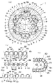
【図1】図1(a)は本発明の一実施の形態に係る転動体連結体としてのボールチェインが適用されるボールスプラインユニットの縦断面図、同図(b)〜(e)はボールチェインを示す図である。
【図2】図2(a)は図1のボールスプラインユニットの一部破断正面図、同図(b)は同図(a)の半断面側面図である。
【図3】図3(a)は図1のボールスプラインユニットの外筒の断面図、同図(b)は外筒の端面図、同図(c)はボールチェインを用いない場合のボール転動溝部の部分断面図、同図(d),(e)はボールチェインの触れ止めのみ案内部を設けたボール転動溝部の部分断面図である。
【図4】図4(a)は側蓋の縦断面図、同図(b),(c)は外筒と側蓋の係合状態を示す図である。
【図5】図5(a)〜(f)は図1のボールチェインの変形例を示す図である。
【符号の説明】
1 ボールスプラインユニット
2 負荷ボール転動溝(外筒側)
3 外筒
4 無負荷ボール通路
5 側蓋
6a 第1樹脂部端縁(リテーナ部)
6b 第2樹脂部端縁(リテーナ部)
7 ボール転動溝(スプライン軸側)
8 スプライン軸
8a 角部
9 ボール(転動体)
10 第1U字溝
11 第2U字溝
12 第2樹脂部
18 第3樹脂部
19a 方向転換路内周部
19b 方向転換路外周部
60 ボールチェイン(転動体連結体)
61 ボール保持部
62 連結部
63 保持板
63a 保持穴
64 保持ピース
65 スリット[0001]
BACKGROUND OF THE INVENTION
The present invention relates to a rolling element used to reduce friction between two members that are in contact with each other so as to be relatively movable, and more particularly to a rolling element coupling body in which a large number of rolling elements are connected in a row.
[0002]
[Prior art]
Conventionally, this kind of rolling element coupling body generally has a plurality of rolling elements, a spacer part interposed between the rolling elements, and is formed in a longitudinal shape so as to be flexible. And the connecting portions are provided on both sides of the row of the spacer portions.
[0003]
[Problems to be solved by the invention]
However, in the case of the prior art as described above, in an apparatus having rolling element circulation paths in which the connecting parts on the left and right of the rolling elements are located on the inner circumference and the outer circumference of the curved part of the rolling element circulation path, Since the difference in circumference becomes large, a case where the curved portion cannot be passed occurs.
[0004]
The present invention has been made to solve the above-described problems of the prior art, and an object of the present invention is to provide a rolling element coupling body that can smoothly guide the rolling elements regardless of the structure of the rolling element circulation path. There is.
[0005]
[Means for Solving the Problems]
In order to achieve the above object, according to the present invention, a plurality of rolling elements, a spacer part interposed between the rolling elements, and a longitudinally formed and flexible said spacer. Each of the parts includes a connecting part that connects in a row, and the connecting part is provided on one side of the row of the spacers.
[0006]
In this way, even when the connecting portion is located on the inner periphery or the outer periphery of the bending portion of the rolling element circulation path of the apparatus, the connecting portion is only on one side of the spacer portion, so that the deformation follows the bending portion of the connecting portion. And smoothly passes through the curved portion.
[0007]
Each spacer is formed with a slit and is divided into two parts in the front and rear.
[0008]
In this way, when located at the curved portion of the circulation path, the difference between the circumferential lengths of the inner peripheral side and the outer peripheral side of the curved portion is absorbed by opening and closing the slit, and the curved portion can be passed more smoothly. .
[0009]
A plurality of rolling elements; a spacer part interposed between the rolling elements; and a connecting part formed in a longitudinal shape and having flexibility so as to connect the spacer parts in a row. Become
A slit is formed on one side of each of the spacers and is divided into two parts in the front and rear. The divided part is a holding piece that slides against the rolling element and holds the rolling element.
[0010]
Thus, even if the slit is provided only on one side of the spacer portion, the difference in circumferential length between the inner and outer circumferences of the bending portion is absorbed by the slit, so that the rolling element coupling body passes smoothly through the bending portion.
[0011]
Furthermore, if the division part divided | segmented by the slit is made into a holding | maintenance piece, a rolling element can be hold | maintained reliably and falling-off of a rolling element can be prevented. This simplifies installation.
[0012]
DETAILED DESCRIPTION OF THE INVENTION
The present invention will be described below based on the illustrated embodiments.
[0013]
1 and 2 show a ball spline unit as an example of an apparatus incorporating a ball chain as a rolling element coupling body according to
[0014]
First, the ball spline unit will be described. The
[0015]
The
[0016]
On the other hand, the
[0017]
The contact angle line L connecting the contact points of the
[0018]
Six rows of
[0019]
The
[0020]
Further, the
[0021]
Each
[0022]
On the other hand, the connecting
[0023]
The
[0024]
In this embodiment, since each
[0025]
Even if the radius of curvature of the direction change path 19 is small, the
[0026]
As shown in FIG. 3A, the load
[0027]
Further, a second
[0028]
An unloaded
[0029]
Further, the
[0030]
On the outer periphery of the
[0031]
The first
[0032]
As shown in FIG. 3B, the
[0033]
At the end surface of the
[0034]
On the other hand, as shown in FIG. 4, the
[0035]
In addition, an
[0036]
[0037]
That is, on the inner peripheral surface of the no-
[0038]
Even if the
[0039]
Even when the
[0040]
The
[0041]
FIG. 5 shows a ball chain as a rolling element retainer according to another embodiment of the present invention.
[0042]
FIGS. 5A and 5B are examples in which the connecting
[0043]
Each
[0044]
The width of the
[0045]
As shown in FIG. 5C, the
[0046]
Of course, as shown in FIG. 5 (d), the position of the connecting
[0047]
In FIG. 5 (e), a connecting
[0048]
FIG. 5F shows an example in which the connecting
[0049]
As described above, since the connecting
[0050]
In the above embodiment, the case where the ball chain as the rolling element coupling body of the present invention is attached to the ball spline unit is exemplified, but the linear motion including the rolling circuit having a curved portion such as a direction changing path, Of course, the present invention can be widely applied to various rolling motion guide devices that guide arc motion, spiral motion, and the like.
[0051]
【The invention's effect】
As described above, according to the present invention, since the connecting portion that connects one side of the row of spacer portions interposed between the rolling elements is provided, the inner circumference of the bending portion of the rolling element circulation path of the apparatus or Even when the connecting portion is located on the outer periphery, the connecting portion is deformed following the bending portion and smoothly passes through the bending portion regardless of the difference in circumferential length between the inner and outer periphery of the bending portion.
[0052]
If each spacer is divided into two parts with slits, the difference in circumference between the inner and outer circumferences of the curved part is absorbed by the opening and closing of the slit when positioned at the curved part of the circulation path. In combination with the provision on only one side of the spacer portion, the curved portion can be passed more smoothly.
[0053]
Further, even if a slit is provided only on one side of the spacer portion regardless of the connecting portion, the difference in circumferential length between the inner and outer circumferences of the bending portion is absorbed by the slit, so that the bending portion passes smoothly.
[0054]
Moreover, if each division part of the spacer part divided | segmented by the slit is made into the holding piece which hold | maintains a rolling element, a rolling element can be hold | maintained reliably and drop-off | omission of a rolling element can be prevented.
[Brief description of the drawings]
FIG. 1 (a) is a longitudinal sectional view of a ball spline unit to which a ball chain as a rolling element coupling body according to an embodiment of the present invention is applied, and FIGS. It is a figure which shows a chain.
2 (a) is a partially broken front view of the ball spline unit of FIG. 1, and FIG. 2 (b) is a half sectional side view of FIG. 2 (a).
3 (a) is a cross-sectional view of the outer cylinder of the ball spline unit of FIG. 1, FIG. 3 (b) is an end view of the outer cylinder, and FIG. 3 (c) is a ball roll without a ball chain. The partial cross-sectional views of the moving groove portion are shown in FIGS. 4D and 4E, which are partial cross-sectional views of the ball rolling groove portion provided with a guide portion only for touching the ball chain.
4 (a) is a longitudinal sectional view of a side cover, and FIGS. 4 (b) and (c) are views showing an engagement state between an outer cylinder and a side cover. FIG.
FIGS. 5A to 5F are views showing a modification of the ball chain of FIG.
[Explanation of symbols]
1
3
6b 2nd resin part edge (retainer part)
7 Ball rolling groove (spline shaft side)
8
10 1st
61
Claims (1)
前記間座部各々はスリットが形成されて前後で2分割され、
前記間座部の分割部が前記転動体に摺接して前記転動体を保持する保持ピースとされている
ことを特徴とする転動体連結体。It comprises a plurality of rolling elements, a spacer part interposed between the rolling elements, and a connecting part that is formed in a longitudinal shape and has flexibility and connects the spacer parts in a row, the connecting portion is provided with and a belt-shaped member on only one side of the column of the respective spacer portions, the other side of the column of the respective spacer portions are not connected,
Each of the spacers is divided into two parts at the front and rear with a slit formed,
A rolling element coupling body, wherein the split portion of the spacer is a holding piece that holds the rolling element in sliding contact with the rolling element.
Priority Applications (1)
| Application Number | Priority Date | Filing Date | Title |
|---|---|---|---|
| JP34366097A JP3670826B2 (en) | 1997-12-01 | 1997-12-01 | Rolling body connected body |
Applications Claiming Priority (1)
| Application Number | Priority Date | Filing Date | Title |
|---|---|---|---|
| JP34366097A JP3670826B2 (en) | 1997-12-01 | 1997-12-01 | Rolling body connected body |
Related Parent Applications (1)
| Application Number | Title | Priority Date | Filing Date |
|---|---|---|---|
| JP06169896A Division JP3533031B2 (en) | 1996-02-23 | 1996-02-23 | Ball spline unit and method of forming outer cylinder of ball spline unit |
Publications (2)
| Publication Number | Publication Date |
|---|---|
| JPH10196652A JPH10196652A (en) | 1998-07-31 |
| JP3670826B2 true JP3670826B2 (en) | 2005-07-13 |
Family
ID=18363260
Family Applications (1)
| Application Number | Title | Priority Date | Filing Date |
|---|---|---|---|
| JP34366097A Expired - Lifetime JP3670826B2 (en) | 1997-12-01 | 1997-12-01 | Rolling body connected body |
Country Status (1)
| Country | Link |
|---|---|
| JP (1) | JP3670826B2 (en) |
Families Citing this family (2)
| Publication number | Priority date | Publication date | Assignee | Title |
|---|---|---|---|---|
| JP4562390B2 (en) | 2003-12-26 | 2010-10-13 | Thk株式会社 | Ball spline |
| JP4675326B2 (en) * | 2004-09-08 | 2011-04-20 | Thk株式会社 | Ball spline device |
-
1997
- 1997-12-01 JP JP34366097A patent/JP3670826B2/en not_active Expired - Lifetime
Also Published As
| Publication number | Publication date |
|---|---|
| JPH10196652A (en) | 1998-07-31 |
Similar Documents
| Publication | Publication Date | Title |
|---|---|---|
| JP4568453B2 (en) | Exercise guidance device | |
| JP3702012B2 (en) | Linear motion rolling guide unit | |
| KR100381276B1 (en) | Ball connecting body and ball screw apparatus using the same | |
| JPH1122727A (en) | Rolling element coupling body, linear guide device using the body, and rolling body screw device | |
| US7465094B2 (en) | Linear guide apparatus | |
| JPH11270650A (en) | Ball screw device | |
| WO2008065878A1 (en) | Ball spline device | |
| JP2007092898A (en) | Rolling element-storing belt for linear guide device and linear guide device | |
| JP3343195B2 (en) | Roller chain | |
| US5092685A (en) | Sealing structure for linear motion bearing | |
| JP3670826B2 (en) | Rolling body connected body | |
| EP0989314B1 (en) | Roller connector and linear guide unit using the same | |
| JP4025563B2 (en) | Linear motion guide unit with separator between rollers | |
| JP4285286B2 (en) | Linear motion guide bearing device | |
| JP2007092899A (en) | Rolling element-storing belt for linear guide device and linear guide device | |
| JP4098381B2 (en) | SPACER MEMBER FOR ROLLING GUIDE DEVICE AND ROLLING GUIDE DEVICE USING THE SAME | |
| US7465093B2 (en) | Linear guide apparatus | |
| JP3256363B2 (en) | Linear guide device | |
| JP2008175324A (en) | Ball connection body | |
| JP3523973B2 (en) | Linear guide device using ball chain | |
| WO2011048892A1 (en) | Motion guiding device | |
| US20080317391A1 (en) | Parallel Spacer for a Linear Guideway | |
| JP3646243B2 (en) | Roller coupling body and linear guide device incorporating the roller coupling body | |
| JP4093172B2 (en) | Linear motion guide bearing device | |
| JP2001140879A (en) | Roller connector and roller guide device |
Legal Events
| Date | Code | Title | Description |
|---|---|---|---|
| A02 | Decision of refusal |
Free format text: JAPANESE INTERMEDIATE CODE: A02 Effective date: 20020827 |
|
| A61 | First payment of annual fees (during grant procedure) |
Free format text: JAPANESE INTERMEDIATE CODE: A61 Effective date: 20050415 |
|
| R150 | Certificate of patent or registration of utility model |
Free format text: JAPANESE INTERMEDIATE CODE: R150 |
|
| FPAY | Renewal fee payment (event date is renewal date of database) |
Free format text: PAYMENT UNTIL: 20090422 Year of fee payment: 4 |
|
| FPAY | Renewal fee payment (event date is renewal date of database) |
Free format text: PAYMENT UNTIL: 20090422 Year of fee payment: 4 |
|
| FPAY | Renewal fee payment (event date is renewal date of database) |
Free format text: PAYMENT UNTIL: 20100422 Year of fee payment: 5 |
|
| FPAY | Renewal fee payment (event date is renewal date of database) |
Free format text: PAYMENT UNTIL: 20110422 Year of fee payment: 6 |
|
| FPAY | Renewal fee payment (event date is renewal date of database) |
Free format text: PAYMENT UNTIL: 20120422 Year of fee payment: 7 |
|
| FPAY | Renewal fee payment (event date is renewal date of database) |
Free format text: PAYMENT UNTIL: 20130422 Year of fee payment: 8 |
|
| FPAY | Renewal fee payment (event date is renewal date of database) |
Free format text: PAYMENT UNTIL: 20130422 Year of fee payment: 8 |
|
| FPAY | Renewal fee payment (event date is renewal date of database) |
Free format text: PAYMENT UNTIL: 20140422 Year of fee payment: 9 |
|
| R250 | Receipt of annual fees |
Free format text: JAPANESE INTERMEDIATE CODE: R250 |
|
| R250 | Receipt of annual fees |
Free format text: JAPANESE INTERMEDIATE CODE: R250 |
|
| EXPY | Cancellation because of completion of term |