JP3670582B2 - Automatic manufacturing method and printing method of astigmatism contact lens and apparatus therefor - Google Patents
Automatic manufacturing method and printing method of astigmatism contact lens and apparatus therefor Download PDFInfo
- Publication number
- JP3670582B2 JP3670582B2 JP2000512680A JP2000512680A JP3670582B2 JP 3670582 B2 JP3670582 B2 JP 3670582B2 JP 2000512680 A JP2000512680 A JP 2000512680A JP 2000512680 A JP2000512680 A JP 2000512680A JP 3670582 B2 JP3670582 B2 JP 3670582B2
- Authority
- JP
- Japan
- Prior art keywords
- toric
- casting cup
- pallet
- lens
- cup
- Prior art date
- Legal status (The legal status is an assumption and is not a legal conclusion. Google has not performed a legal analysis and makes no representation as to the accuracy of the status listed.)
- Expired - Fee Related
Links
Images


Classifications
-
- B—PERFORMING OPERATIONS; TRANSPORTING
- B29—WORKING OF PLASTICS; WORKING OF SUBSTANCES IN A PLASTIC STATE IN GENERAL
- B29D—PRODUCING PARTICULAR ARTICLES FROM PLASTICS OR FROM SUBSTANCES IN A PLASTIC STATE
- B29D11/00—Producing optical elements, e.g. lenses or prisms
-
- B—PERFORMING OPERATIONS; TRANSPORTING
- B29—WORKING OF PLASTICS; WORKING OF SUBSTANCES IN A PLASTIC STATE IN GENERAL
- B29D—PRODUCING PARTICULAR ARTICLES FROM PLASTICS OR FROM SUBSTANCES IN A PLASTIC STATE
- B29D11/00—Producing optical elements, e.g. lenses or prisms
- B29D11/00009—Production of simple or compound lenses
- B29D11/00038—Production of contact lenses
- B29D11/00125—Auxiliary operations, e.g. removing oxygen from the mould, conveying moulds from a storage to the production line in an inert atmosphere
- B29D11/00173—Conveying moulds
- B29D11/00182—Conveying moulds using carrier plates
-
- B—PERFORMING OPERATIONS; TRANSPORTING
- B29—WORKING OF PLASTICS; WORKING OF SUBSTANCES IN A PLASTIC STATE IN GENERAL
- B29C—SHAPING OR JOINING OF PLASTICS; SHAPING OF MATERIAL IN A PLASTIC STATE, NOT OTHERWISE PROVIDED FOR; AFTER-TREATMENT OF THE SHAPED PRODUCTS, e.g. REPAIRING
- B29C31/00—Handling, e.g. feeding of the material to be shaped, storage of plastics material before moulding; Automation, i.e. automated handling lines in plastics processing plants, e.g. using manipulators or robots
- B29C31/006—Handling moulds, e.g. between a mould store and a moulding machine
-
- B—PERFORMING OPERATIONS; TRANSPORTING
- B29—WORKING OF PLASTICS; WORKING OF SUBSTANCES IN A PLASTIC STATE IN GENERAL
- B29D—PRODUCING PARTICULAR ARTICLES FROM PLASTICS OR FROM SUBSTANCES IN A PLASTIC STATE
- B29D11/00—Producing optical elements, e.g. lenses or prisms
- B29D11/00009—Production of simple or compound lenses
- B29D11/00019—Production of simple or compound lenses with non-spherical faces, e.g. toric faces
-
- B—PERFORMING OPERATIONS; TRANSPORTING
- B29—WORKING OF PLASTICS; WORKING OF SUBSTANCES IN A PLASTIC STATE IN GENERAL
- B29D—PRODUCING PARTICULAR ARTICLES FROM PLASTICS OR FROM SUBSTANCES IN A PLASTIC STATE
- B29D11/00—Producing optical elements, e.g. lenses or prisms
- B29D11/00009—Production of simple or compound lenses
- B29D11/00317—Production of lenses with markings or patterns
-
- B—PERFORMING OPERATIONS; TRANSPORTING
- B29—WORKING OF PLASTICS; WORKING OF SUBSTANCES IN A PLASTIC STATE IN GENERAL
- B29D—PRODUCING PARTICULAR ARTICLES FROM PLASTICS OR FROM SUBSTANCES IN A PLASTIC STATE
- B29D11/00—Producing optical elements, e.g. lenses or prisms
- B29D11/00009—Production of simple or compound lenses
- B29D11/00423—Plants for the production of simple or compound lenses
-
- B—PERFORMING OPERATIONS; TRANSPORTING
- B29—WORKING OF PLASTICS; WORKING OF SUBSTANCES IN A PLASTIC STATE IN GENERAL
- B29D—PRODUCING PARTICULAR ARTICLES FROM PLASTICS OR FROM SUBSTANCES IN A PLASTIC STATE
- B29D11/00—Producing optical elements, e.g. lenses or prisms
- B29D11/00865—Applying coatings; tinting; colouring
- B29D11/00894—Applying coatings; tinting; colouring colouring or tinting
- B29D11/00903—Applying coatings; tinting; colouring colouring or tinting on the surface
-
- Y—GENERAL TAGGING OF NEW TECHNOLOGICAL DEVELOPMENTS; GENERAL TAGGING OF CROSS-SECTIONAL TECHNOLOGIES SPANNING OVER SEVERAL SECTIONS OF THE IPC; TECHNICAL SUBJECTS COVERED BY FORMER USPC CROSS-REFERENCE ART COLLECTIONS [XRACs] AND DIGESTS
- Y10—TECHNICAL SUBJECTS COVERED BY FORMER USPC
- Y10S—TECHNICAL SUBJECTS COVERED BY FORMER USPC CROSS-REFERENCE ART COLLECTIONS [XRACs] AND DIGESTS
- Y10S425/00—Plastic article or earthenware shaping or treating: apparatus
- Y10S425/808—Lens mold
Landscapes
- Engineering & Computer Science (AREA)
- Mechanical Engineering (AREA)
- Health & Medical Sciences (AREA)
- Manufacturing & Machinery (AREA)
- Ophthalmology & Optometry (AREA)
- Robotics (AREA)
- Eyeglasses (AREA)
Description
【0001】
この出願は、1997年9月24日に出願された米国仮特許出願第60/059,932号の継続出願である。
【0002】
発明の背景
乱視は、非球面処方のレンズにより矯正される目の障害である。患者の処方注文上で通常は円柱として表されるこの処方は、レンズ表面の少なくとも一部に、円環体切片の形状をもたせる。従って、このようなレンズは円環体レンズと呼ばれる。
【0003】
コンタクトレンズの背面は一般に形状が球面であるが、該レンズを使用して乱視を矯正する場合、それは円環体の形状を有するであろう。即ち、レンズ背面の曲面部分は主軸および副軸を有し、該レンズ背面の曲率半径は、副軸方向よりも主軸方向の方が長い。その結果、該レンズの背面は球形状ではなく、主軸が副軸に対して直交する円環体形状を有する。この円環体曲面の主直径は、一般にはレンズ全体よりも直径が小さく、球形状を有する出発ベース曲面にカットされる。
【0004】
当該矯正レンズは、着用者の目に対して適性に方向を合わせなければならない。即ち、レンズの意図した頂部が着用者の目の頂部になければならない。通常の眼鏡の場合は、レンズが正しい回転の向きでフレームに永久的に固定されるから、これには何の問題もない。フレームの目ピースおよび鼻ピースは、該フレームおよびレンズが、着用者の目に対して回転しないことを保証する。コンタクトレンズの向きは、一定の変更を受ける。その機能が乱視の矯正であるコンタクトレンズの場合、これは容認できない。
【0005】
乱視の矯正に使用するために設計されたソフトコンタクトレンズは、当該技術において周知である。一般にこれらのレンズは、レンズを目の適正な位置に配置するために、幾つかの安定させる方法に依存する。乱視矯正用の理想的なレンズは、良好な回転の向きを有している。即ち、レンズの意図した頂部は、レンズを着用したときに、着用者の目の頂部に位置しなければならない。レンズの取り付け者が変位を測定し、また変位をレンズの処方に考慮するとすれば、正しい向きからの僅かな変位は許容され得る。
【0006】
また、理想的なレンズは良好な回転安定性を提供する。即ち、レンズは全着用期間に亘って、目の中に固定された回転の向きで存在していなければならない。更に、このレンズは、それが着用される毎に同じ向きを取らなければならない。また、当然ながら、レンズが薄く且つレンズ表面が平滑であるほど、レンズは着用者に対してより快適な感じを与えるであろう。
【0007】
本発明によるレンズは、好ましくはソフトコンタクトレンズであり、これは当業者に公知のように、ヒドロキシエチルメタクリレート、有機金属物質、シリコーンゴムおよび他の種々の材料を含む多くの材料で形成することができる。好ましいソフトコンタクトレンズは親水性である。即ち、それらは水を吸収し、事実、この水はコンタクトレンズ表面に一体化してその一部になる。親水性のコンタクトレンズは、当業者に公知のように、本発明を実施するために特に好ましいものである。
【0008】
乱視を矯正するために使用されるコンタクトレンズは以前から普及しているが、これらのレンズを製造するためのコストはこれまで低下していない。一部は、多くの異なった数のレンズが必要とされることに起因して、少量生産のためにコストは高いままである。例えば、円環体レンズが10°の安定変動量のために回転的に構成されるとすれば、夫々の処方について可能なレンズの全数を考慮すると、36の異なったレンズを製造しなければならないであろう。これは、非円環体レンズのために必要とされる1個の形状とは対照的である。更に、乱視処方の数は正規の非円環体処方よりも少ないから、円環体レンズの数は上記で論じた36対1の比よりも更に少ない。
【0009】
発明の概要
本明細書で説明する本願発明は、付随するコストを大幅に低減する円環体コンタクトレンズを自動的に製造する方法を提供する。キャスティングカップ同士の間で、正確でプログラム可能な回転配置を提供することによって、円環体レンズは非円環体レンズと同じ速度で製造することができ、それにより、円環体処方を変えることは製造プロセスの休止時間を生じない。自動充填および閉鎖機械は、キャスティングカップ同士を含むパレットから製造すべき円環体レンズに関する情報を得る。この情報が自動充填および閉鎖機械に伝えられた後、プログラム可能なコントローラが充填および閉鎖機械を駆動し、次いで、該機械は正確な円環体の回転配置を有する特定の円環体レンズを製造するように作動する。特定の数のレンズが製造されたら、前記プログラム可能なコントローラは、次のパレットタグから新たな情報を得て、キャスティングカップアセンブリーを新たな回転配置へと回転させるように作動し、これによって異なった円環体回転配置をもった円環体レンズを製造する。このプロセスは、同じ円環体回転配置をもった同じ数のコンタクトレンズを作製するために要する時間と同一か、または同様の時間で、異なる回転配置を持った複数の円環体レンズの製造を可能にする。より小さいバッチの円環体レンズを、より大きなバッチの同じ円環体レンズを製造するのに要するのと同じ時間で製造することができる。
【0010】
本発明の目的は、モールドキャスティングカップに液状モノマーを正確に充填し、このキャスティングカップの半型(即ち、前方曲面およびベース曲面)を、キャスティング半型同士の間で、正確でプログラム可能な回転配置を維持しながら、正確に制御された動作の下で再組立てできる装置を提供することである。
【0011】
本発明のもう一つの目的は、モールドコンタクトレンズのキャスティングカップの一方の半型に液状モノマーを充填し、また、キャスティングカップアセンブリーの他方の半型が別の半型に近接して回転可能に配置され、これにより円環体コンタクトレンズを製造するようにプログラムされたプログラム可能で且つ正確な充填および閉鎖装置を使用することにより、乱視用又は円環体コンタクトレンズを製造する方法を提供することである。
【0012】
本発明のもう一つの目的は、キャスティングキャップアセンブリーの回転配置を自動的に変更し、これにより、新たな処方の円環体レンズを、休止時間または切替え時間をゼロにして製造できる方法を提供することである。
【0013】
本発明のもう一つの目的は、コンタクトレンズの前面に、軸方向フィーチャーを正確に印刷することにより、円環体コンタクトレンズの着用者の目への適正な装着および安定性を補助するための、完全に自動化された印刷システムを提供することである。
【0014】
本発明のもう一つの目的は、円環体コンタクトレンズを含むパレットを、コンベアを介して印刷ゾーンに挿入することにより、円環体レンズに正確な軸方向フィーチャーを自動的に印刷する方法を提供することである。次いで、コード化された情報を用いることにより、コード化された情報により決定されたマーク位置で、自動印刷装置が軸方向マークをシリコーン印刷パッドに塗布する。次いで、軸方向フィーチャーまたは虹彩印刷を塗布できるように、コンタクトレンズを正しい位置に保持する。最後に、キャスティングカップをビデオ検査のために位置決めすることにより、キャスティングカップ上での軸方向フィーチャーの位置を確認する。
【0015】
本発明のこれら特徴および他の重要な特徴、並びに利点は、添付の図面を参照し、本発明の下記の詳細な実施例の説明を読むことによって明らかになるであろう。
【0016】
本発明の実施態様の詳細な説明
図1は、乱視用または円環体レンズを自動的に製造し、レンズの上に印刷するための本発明による装置の平面図を示している。自動的充填および閉鎖機械10は、パレット送り込みコンベアアセンブリー14、円環体充填および閉鎖ベースユニットアセンブリー16、パレットアンロードアセンブリー18、およびプログラム可能なコントローラ20でできている。パレットコンベア22が、ダミー送り込みコンベアおよびパレット送り込みコンベア14、円環体充填および閉鎖ベースユニットアセンブリー16、並びにパレットアンロードアセンブリー18を横切っている。該パレットコンベアは、各パレット24を、処理のためにパレット送り込みコンベア14から円環体充填および閉鎖ベースユニットアセンブリー16へと移動させ、次いで、充填されたキャスティングカップアセンブリー26を含む硬化パレット25を、更なる処理のためにパレットアンロードアセンブリー18へ送る。各パレット24は、複数の、好ましくは8個の、円環体レンズの製造に使用されるキャスティングカップアセンブリー26を含んでいる。
【0017】
プログラム可能なコントローラ20は、機械10から離間して位置することにより、オペレータ30による製造ゾーンへの最大のアクセス可能性を与える。プログラム可能なコントローラ20は、多くの商業的に入手可能なコントローラのうちの一つであればよく、好ましくは、Rockwell Software RSLogix 500ソフトウエアを用いたAllen-Bradley社のプログラム可能なコントローラSLC500である。充填および閉鎖機械10を制御するために使用されるソフトウエアは、梯子型ソフトウエアプロトコールである。プログラム可能なコントローラ20は、データの入力および出力のために、タッチ画面ディスプレー28を使用する。このタッチ画面ディスプレー28はまた、図2に示したように、充填および閉鎖機械10のマニュアル操作にも用いられる。以下で述べるように、自動充填および閉鎖モードにおいて、適切な円環体の回転設定は、パレット24に取りつけられた情報タグ27(図7参照)からコントローラにより受信された情報に基づいて、プログラム可能なコントローラ20によって制御される。好ましいタイプの情報タグ27は、Pepperi-Fuchsリーダーと共にPepperi-Fuchsによって製造された誘電体タグである。バーコードシステム、読取り可能な他の媒体およびタッチメモリーにような、他の種類の情報タグを使用してもよい。パレットアンロードアセンブリー18は、図1および図3に示すように、第一の脱スタッカ32および第二の脱スタッカ34、およびパレットアンロードコンベア36からなっている。パレットアンロードアセンブリー18はまた、四本のショットピン38および二つの空気圧リフト40を利用する。充填および閉鎖のプロセスが完了した後、処理されたパレットは、コンベア22を介して、硬化させるためにパレットアンロードコンベア36へと送給される。
【0018】
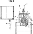
図4は、充填および閉鎖ベースユニットアセンブリー16の正面図を示している。ベースユニットアセンブリー16は、就中、ピックおよび位置閉鎖モータ42、親ネジ44、およびグリップ顎部47を含む上部閉鎖ヘッド46を含んでいる。この親ネジ44と共に使用されるモータ42は、上部閉鎖ヘッドまたはピックおよび配置ヘッド46を上昇および下降させ、またグリップ顎部47を開放および閉鎖する。また、充填および閉鎖ベースユニットアセンブリー16には、割り出しコンベアサーボ48およびロータリー駆動ステップモータおよびコントローラ50が配置されている。充填および閉鎖ベースユニットアセンブリー16はまた、ロットトラッキング読取りゾーン52およびロットトラッキング書込みゾーン54を利用する。
【0019】
自動充填および閉鎖機械10は、図1、図3および図4を参照して以下で説明するように、本発明に従って乱視用コンタクトレンズを製造するために使用される。
【0020】
充填および閉鎖機械10の目的は、モールドされたキャスティングカップ26、好ましくは前方凹面キャスティングカップに液状モノマーを正確に充填し、キャスティングカップの半型同士、即ち、前方凹面半型およびベース凸面半型を、キャスティングカップ半型同士間で正確でプログラム可能な回転配置を維持しながら、正確に制御された動作の下で再組立てすることである。
【0021】
このプロセスを達成するために、パレットまたは複数のパレット24が、充填および閉鎖機械10にロードされる。パレット24が、パレット送り込みコンベア14上の正しい位置にあることをコントローラ20が検知すると、パレット24はコンベア22上の位置へと往復する。同時に、硬化パレット25が脱スタッカ32,34の一方の上にスタックされる。線形アクチュエータ、好ましくはBarrington自動化線形アクチュエータがその完全な頂部ストロークに行くと、これは全てのパレットがスタックされ且つショットピン38でロックされたことを意味する。空気圧リフト40を用いることにより、全体のスタックが好ましくは1000分の30インチだけ持ち上げられて、ピン38が解除される。中間ストロークのシリンダが始動され、全行程を往復作動して、線形アクチュエータは後退するであろう。底部シリンダは線形アクチュエータよりも強いから、該アクチュエータは中間ストロークで重ねられるであろう。全体のスタックが、好ましくは3/4インチ、またはパレットの厚さだけ下降する。今度は、ショットピン38が始動して全体のスタックをロックするが、一つの硬化パレット25をこのスタックから外す。中間ストロークのシリンダおよび線形アクチュエータが完全に後退し、当該プロセスで利用できるようにパレットをトラックに降ろす。
【0022】
今や、パレット24および硬化パレット25は使用できる状態にあり、閉鎖ステーションをアドレスすることができる。パレット24がコンベア22に沿って移動するので、それは充填機、好ましくはOyster Bayポンプユニットに到着する。信号がポンプユニットに送られ、該ポンプユニットは前方曲面カップにモノマーを充填するように作動する。次いで、パレット24は、ピックおよび配置ヘッドの下でコンベア22に沿って配置される。コントローラ20がサーボ42を駆動し、閉鎖ヘッド46および閉鎖顎部47を下降させる。該顎部47は、パレット24から前方曲面キャスティングカップを把持する。顎部47により把持するために、顎部47はその中にV字形ピン56を含んでいる。前方曲面キャスティングカップフランジ60は、その中に雌型のV字形ノッチ58を有している。V字形ピン56は、傾斜または隙間なしに、フランジ60を正確に把持することを意図している。
【0023】
縦方向の運動により、顎部47は、前方曲面キャスティングカップをパレット24の穴から取り出す。パレット24は特別のC字形クリップ62を有しており、該クリップはカップを正しい位置に保持して、把持ピンの組47で最小限の回転のみを可能にする一方、処理を通して角度方向を維持する。次いで、グリップ顎部47は、予め充填された前方曲面キャスティングカップを下部閉鎖ヘッド64の中に配置する(前方曲面キャスティングカップは、必ずしも予め充填される必要はない)。下部閉鎖ヘッドは整列ピンを有しており、該整列ピンは、キャスティングカップフランジのV字形ノッチ58を下部閉鎖ヘッド64の中に正確に配置する。カップはV字形ノッチの場所に保持される一方、V字形ノッチを下部閉鎖ヘッドの位置決めピンの上に配置する。顎部47は、この要件に従うように構成される。
【0024】
パレット24には、プログラム可能なコントローラ20に情報を伝えるための誘電体タグ27が固定されている。Petteri-Fuchsリーダーを介してコントローラ20に伝えられる情報は、特定の円環体レンズが製造されるように、コントローラ20が充填および閉鎖機械10を配置することを可能にする。伝えられた情報に応じて、下部閉鎖ヘッド64は適正な円環体回転軸セッティングを回転させる。機械10は、下部ヘッド64を保持して上部ヘッド46を回転させてもよいが、下部ヘッド64を回転させる方が好ましい。この回転は、正の位置フィードバックのための積分エンコーダ(integral encoder)を有するステップモータ50によって達成される。
【0025】
ベース曲面カップは、ピックおよび配置ヘッド46の下を往復移動され、雄V字形ノッチグリップ顎部47によって把持されて、パレット24から取り出される。前方曲面カップが既に適正な軸セッティングになっているから、このベース曲面カップは回転されない。パレットのC字形クリップ62は二つの機能を行う。それらは、整列のためのグリップ顎部47に追従するようにカップの最小回転のみを可能にし、またパレット24におけるカップの緊密な適合性を与えて、迅速な移動処理行程により揺すりながら、それらを平坦かつ同一平面に維持する。
【0026】
次に、顎部47は、サーボ駆動のプログラム可能な下方移動により、カップセットを閉鎖する。この下方移動は、閉鎖力を調節するカンチレバー式の錘を上昇させる。次いで、過剰のモノマーがカップキャビティーから排出され、閉鎖プロセスを完了する。ピックおよび配置ヘッド46が上昇し、カップアセンブリーを引き上げる。下部ヘッド64はゼロ位置にまで逆に回転して、次のサイクルまで待機する。
【0027】
入れ子式コンベア(nested conveyor)22は、硬化パレット25をピックおよび配置ヘッド46の下で往復させ、カップアセンブリーを硬化パレット25の中に配置する。硬化パレット25はまた、パレットにおけるカップ位置を制御するためのC字形クリップ62を有している。次いで、硬化パレットは、更なる処理のためにコンベア22上に配置され、パレット24はパレット24の処理位置に戻る。
【0028】
円環体レンズが硬化され、キャスティングカップ半型同士が分離されたら、印刷の準備が完了する。この印刷プロセスを、図5および図6を参照して以下で説明する。
【0029】
印刷プロセスは、完全に自動化された印刷機66を利用する。この機械の目的は、軸方向フィーチャーをコンタクトレンズ前面に正確に印刷することである。これは、医者が、患者の目に対するレンズの適正な装着性および安定性を判断するための補助となる。
【0030】
印刷機66は、プレス嵌合法を使用することにより、キャスティングカップ半型(硬化されたコンタクトレンズを含む)を保持するパレット設計と共に働く。キャスティングカップはパレット上のベース曲面構造上にプレス嵌合され、該ベース曲面構造は、ベース局面キャスティングカップの内径よりも略0.0005〜0.001インチだけ大きい外径を有する。僅かに大きい直径を含むパレット上にキャスティングカップが配置されると、ベース曲面キャスティングカップは殆ど動かず、以下で説明するようにして、レンズに印刷を施すことができる。
【0031】
印刷機66はまた、充填および閉鎖機械10で説明したのと同様の、C字形クリップ62を有するパレット設計を利用することができる。C字形クリップ62の目的は、パレット上のベース曲面キャスティングカップを固定し、最小限の回転のみを許容することである。ベース曲線カップが印刷パレット上に挿入される際に、この印刷パレットのC字形クリップ62は、ショットピンとのその回転角の中点に整列されるであろう。この整列は、該カップが、印刷の際にキャスティングカップ26を正確に位置決めするV字形ノッチグリップ顎部47に追従できることを保証するために必要である。
【0032】
印刷機送り込みコンベア68は、予備印刷乾燥オーブンから来る製品パレット25を受け取り、処理のためにパレットを積み重ねる。送り込み積み重ねコンベア68と並行して、パレットおよびレンズの無い空のキャスティングカップに印刷する第二のコンベアまたはダミー送り込みコンベア70が設けられている。この第二のコンベア70を使用して、製品を浪費することなく、方向フィーチャーの位置精度を試験する。パレット25のこれら列の両方が、ロット情報および軸セッティングを印刷コントローラ20に転送するための、誘電体タグまたは情報タグ27を有している。
【0033】
キャスティングカップを印刷ゾーン78の中に持ち込むために、パレット25の何れか一方の列(何れが使用されるとしても)が、サーボ駆動の入れ子式割り出しコンベア72上に押出される。割り出しコンベアシステム72は、ロット一掃(lot cleanout)のためにシステムからの最後のパレットをスピードアップするような、種々の好ましい製造シナリオに異なって適合させるために、システムを通してパレット25を移動させるようにプログラムすることができる。
【0034】
軸方向マークをレンズに配置する前に、該マークは、シリコーン印刷パッド74に塗布されなければならない。これは、モータ駆動のX,Yおよびシータ位置決めシステム76の頂部に装着された、インク供給システムで正確に達成される。この三つの軸は、予備ロードおよび坑逆傾斜(anti-backslash)親ネジキャプスタン設計に接続された積分エンコーダを備えたステップモータにより駆動される。スライドおよび回転ベアリングは、最大の精度および信頼性を保証して製品の標準偏差を最小にするための、坑摩擦性の予備ロード設計である。
【0035】
回転クラッチ版ステーションもまた、放射状ベアリングの頂部に、マニュアルで調節されるX&Yあり継ぎステージを有している。このステージは、エッチングされた軸方向マークを放射状ベアリング上に適正に整列させる。また、軸方向フィーチャーから正確な位置には、クラッチ版にエッチングされた十字線が存在し、クラッチ版の予備的整列を可能にする。マニュアルX&Yあり継ぎスライドを調節して射程の短い望遠鏡または光ファイバカメラおよびモニタ機構を備えたクラッチ板上に十字線を整列させることにより、クラッチ版を予備整列させることができる。適正に調節されたら、クラッチ版ステーションは、X&Yを調節することなく、夫々のロットについて新たな軸方向セッティングへと回転することができる。これは、効率および印刷精度を高めて、歩留りを最大にするであろう。
【0036】
二つのカップ位置探査装置ステーションが存在する。第一のステーションは、キャスティングカップを、軸方向フィーチャーまたは適用される虹彩印刷を有するように、配置し保持する。前方曲面キャスティングカップ半型は、取り付けおよび閉鎖ステージの際に回転可能に整列されるから、軸方向は、印刷時に回転され、取り付けおよび閉鎖回転配置をマッチさせる。第二のステーションは、ビデオ検査ステーションで使用するために、キャスティングカップを配置する。この検査ステーションは、キャスティングカップ上における軸方向フィーチャーの位置を確認する。このシステムはまた、必要であれば該情報を使用して、モータ駆動される回転クラッチ版ステーション上のX,Yおよびシータ位置をダイナミックに調節する。このシステムは、自己修正を可能にし、オペレータの定常的な注意を必要とせずに信頼性のある製造を可能にする。
【0037】
両方の配置ステーションは、キャスティングカップをフランジ60の雌型V字形ノッチ58上に把持する雄型V字形ノッチを有する。次いで、パレット25が、入れ子式の割り出しコンベア72から、どんな追加の処理をも可能にするアンロードコンベア80上に押出される。
【0038】
好ましい実施態様に関連して本発明を説明してきたが、これは、本発明を列記した実施態様に限定することを意図するものではない。逆に、特許請求の範囲に定義した本発明の精神および範囲内に含まれ得る代替物、変形、および均等物をカバーするものである。
【図面の簡単な説明】
【図1】図1は、本発明による充填および閉鎖機械の頂面図を示している。
【図2】図2は、本発明によるプログラム可能なコントローラのディスプレー部分を示している。
【図3】図3は、充填および閉鎖機械の側面図を示している。
【図4】本発明による充填および閉鎖機械の正面図を示している。
【図5】図5は、本発明による印刷機械の頂面図を示している。
【図6】図6は、本発明による印刷機械の側面図を示している。
【図7】図7は、本発明に従って使用されるパレットの頂面図を示している。
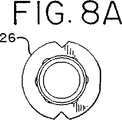
【図8】図8は、本発明に従って使用されるキャスティングカップの頂面図を示している。
【図9】図9は、本発明に従って使用されるグリップ顎部およびキャスティングカップフランジを示している。[0001]
This application is a continuation of US Provisional Patent Application No. 60 / 059,932, filed September 24, 1997.
[0002]
BACKGROUND OF THE INVENTION Astigmatism is an eye disorder that is corrected by an aspheric prescription lens. This prescription, usually represented as a cylinder on the patient's prescription order, causes at least a portion of the lens surface to have the shape of a toric slice. Therefore, such a lens is called a toric lens.
[0003]
The back of a contact lens is generally spherical in shape, but if it is used to correct astigmatism, it will have a toric shape. That is, the curved surface portion of the lens back surface has a main axis and a sub axis, and the radius of curvature of the lens back surface is longer in the main axis direction than in the sub axis direction. As a result, the rear surface of the lens is not spherical, but has a torus shape in which the main axis is orthogonal to the auxiliary axis. The main diameter of the toric curved surface is generally smaller than the entire lens, and is cut into a starting base curved surface having a spherical shape.
[0004]
The corrective lens must be properly oriented with respect to the wearer's eyes. That is, the intended top of the lens must be at the top of the wearer's eye. In the case of normal glasses, this is not a problem because the lens is permanently fixed to the frame in the correct rotational orientation. The eye piece and nose piece of the frame ensure that the frame and lens do not rotate with respect to the wearer's eyes. Contact lens orientation is subject to certain changes. For contact lenses whose function is correction of astigmatism, this is unacceptable.
[0005]
Soft contact lenses designed for use in correcting astigmatism are well known in the art. In general, these lenses rely on several stabilization methods to place the lens in the proper position of the eye. An ideal lens for correcting astigmatism has a good rotational orientation. That is, the intended top of the lens must be located on the top of the wearer's eyes when the lens is worn. If the lens installer measures the displacement and considers the displacement in the lens prescription, a slight displacement from the correct orientation can be tolerated.
[0006]
An ideal lens also provides good rotational stability. That is, the lens must be in a fixed rotational orientation in the eye for the entire wear period. Furthermore, this lens must take the same orientation each time it is worn. Also, of course, the thinner the lens and the smoother the lens surface, the more comfortable the lens will feel to the wearer.
[0007]
The lens according to the present invention is preferably a soft contact lens, which can be formed of a number of materials including hydroxyethyl methacrylate, organometallic materials, silicone rubber and various other materials, as is known to those skilled in the art. it can. Preferred soft contact lenses are hydrophilic. That is, they absorb water, and in fact this water is integrated into the contact lens surface and becomes part of it. Hydrophilic contact lenses are particularly preferred for practicing the present invention, as is known to those skilled in the art.
[0008]
Although contact lenses used to correct astigmatism have been popular for some time, the cost of manufacturing these lenses has not been reduced so far. In part, the cost remains high for low volume production due to the need for many different numbers of lenses. For example, if the toric lens is rotationally configured for a 10 ° stable variation, 36 different lenses must be manufactured considering the total number of lenses possible for each prescription. Will. This is in contrast to the single shape required for non-toric lenses. Furthermore, since the number of astigmatism prescriptions is less than regular non-annular prescriptions, the number of toric lenses is even less than the 36 to 1 ratio discussed above.
[0009]
SUMMARY OF THE INVENTION The present invention described herein provides a method for automatically manufacturing toric contact lenses that significantly reduces the associated costs. By providing an accurate and programmable rotational arrangement between casting cups, toric lenses can be manufactured at the same speed as non-toric lenses, thereby changing the toric formula. Does not cause downtime of the manufacturing process. The automatic filling and closing machine obtains information about the toric lens to be manufactured from the pallet containing the casting cups. After this information is communicated to the automatic filling and closing machine, a programmable controller drives the filling and closing machine, which then produces a specific toric lens with an accurate torus rotational arrangement. Operates to Once a certain number of lenses have been manufactured, the programmable controller will act to obtain new information from the next pallet tag and rotate the casting cup assembly into a new rotational arrangement, depending on which A toric lens having a toric rotating arrangement is manufactured. This process is the same or similar to the time required to make the same number of contact lenses with the same rotational arrangement of the torus, producing multiple toric lenses with different rotational arrangements. to enable. A smaller batch of toric lenses can be produced in the same time required to produce a larger batch of the same toric lens.
[0010]
It is an object of the present invention to accurately fill a mold casting cup with a liquid monomer, and to accurately and programmable rotationally arrange the casting cup halves (ie, the front curved surface and the base curved surface) between the casting halves. Is to provide a device that can be reassembled under precisely controlled operation.
[0011]
Another object of the present invention is to fill one half of the casting cup of the mold contact lens with a liquid monomer and to allow the other half of the casting cup assembly to rotate close to the other half. Providing a method of manufacturing astigmatic or toric contact lenses by using a programmable and accurate filling and closing device arranged and programmed to manufacture toric contact lenses It is.
[0012]
Another object of the present invention is to provide a method by which the rotational arrangement of the casting cap assembly can be automatically changed, thereby producing a new prescription toric lens with zero downtime or switching time. It is to be.
[0013]
Another object of the present invention is to accurately print the axial features on the front surface of the contact lens to assist in proper wearing and stability of the toric contact lens to the wearer's eyes. It is to provide a fully automated printing system.
[0014]
Another object of the present invention is to provide a method for automatically printing precise axial features on toric lenses by inserting a pallet containing toric contact lenses into a print zone via a conveyor. It is to be. Then, using the coded information, the automatic printing device applies an axial mark to the silicone printing pad at the mark position determined by the coded information. The contact lens is then held in place so that an axial feature or iris print can be applied. Finally, the position of the axial feature on the casting cup is ascertained by positioning the casting cup for video inspection.
[0015]
These and other important features and advantages of the present invention will become apparent upon reading the following detailed description of the embodiments of the present invention with reference to the accompanying drawings.
[0016]
DETAILED DESCRIPTION OF EMBODIMENTS OF THE INVENTION FIG. 1 shows a plan view of an apparatus according to the invention for automatically manufacturing astigmatic or toric lenses and printing on the lenses. The automatic filling and closing machine 10 is comprised of a pallet infeed conveyor assembly 14, a torus filling and closing
[0017]
The
[0018]
FIG. 4 shows a front view of the filling and closing
[0019]
The automatic filling and closing machine 10 is used to manufacture astigmatic contact lenses according to the present invention, as will be described below with reference to FIGS.
[0020]
The purpose of the filling and closing machine 10 is to accurately fill the molded
[0021]
To accomplish this process, a pallet or
[0022]
The
[0023]
By the vertical movement, the
[0024]
A
[0025]
The base curved cup is reciprocated under the pick and
[0026]
The
[0027]
A nested
[0028]
When the toric lens is cured and the casting cup halves are separated from each other, the preparation for printing is completed. This printing process is described below with reference to FIGS.
[0029]
The printing process utilizes a fully automated printing machine 66. The purpose of this machine is to accurately print axial features on the front surface of contact lenses. This assists the physician in determining the proper fit and stability of the lens to the patient's eyes.
[0030]
The printing press 66 works with a pallet design that holds the casting cup half (including the cured contact lens) by using a press-fit method. The casting cup is press fitted onto a base curved surface structure on the pallet, the base curved surface structure having an outer diameter that is approximately 0.0005 to 0.001 inches larger than the inner diameter of the base phase casting cup. When the casting cup is placed on a pallet that includes a slightly larger diameter, the base curved casting cup moves little and the lens can be printed as described below.
[0031]
The printing machine 66 can also utilize a pallet design with a C-shaped
[0032]
The
[0033]
To bring the casting cup into the
[0034]
Prior to placing the axial mark on the lens, the mark must be applied to the
[0035]
The rotary clutch plate station also has a manually adjusted X & Y splice stage at the top of the radial bearing. This stage properly aligns the etched axial marks on the radial bearing. Also, there is a crosshair etched in the clutch plate at a precise location from the axial feature, allowing pre-alignment of the clutch plate. The clutch plate can be pre-aligned by adjusting the manual X & Y joint slide to align the crosshairs on a short range telescope or fiber optic camera and a clutch plate with a monitor mechanism. When properly adjusted, the clutch station can be rotated to a new axial setting for each lot without adjusting X & Y. This will increase efficiency and printing accuracy and maximize yield.
[0036]
There are two cup positioner stations. The first station positions and holds the casting cup with axial features or applied iris prints. Since the front curved casting cup halves are rotatably aligned during the mounting and closing stages, the axial direction is rotated during printing to match the mounting and closing rotational arrangements. The second station places a casting cup for use at the video inspection station. This inspection station confirms the position of the axial feature on the casting cup. The system also uses the information if necessary to dynamically adjust the X, Y and theta positions on the motorized rotating clutch plate station. This system allows self-correction and enables reliable manufacturing without the need for constant operator attention.
[0037]
Both placement stations have a male V-shaped notch that grips the casting cup on the female V-shaped
[0038]
Although the invention has been described with reference to preferred embodiments, it is not intended to limit the invention to the listed embodiments. On the contrary, the intention is to cover alternatives, modifications and equivalents that may be included within the spirit and scope of the invention as defined by the claims.
[Brief description of the drawings]
FIG. 1 shows a top view of a filling and closing machine according to the invention.
FIG. 2 shows the display portion of a programmable controller according to the present invention.
FIG. 3 shows a side view of the filling and closing machine.
FIG. 4 shows a front view of a filling and closing machine according to the invention.
FIG. 5 shows a top view of a printing machine according to the present invention.
FIG. 6 shows a side view of a printing machine according to the present invention.
FIG. 7 shows a top view of a pallet used in accordance with the present invention.
FIG. 8 shows a top view of a casting cup used in accordance with the present invention.
FIG. 9 shows a grip jaw and a casting cup flange used in accordance with the present invention.
Claims (9)
a)第一の円環体レンズキャスティングカップ半型及び第二の円環体レンズキャスティングカップ半型、並びに情報タグを含むパレットを、コンベア上に配置する工程と;
b)前記パレットを充填アセンブリーの下に配置する工程と;
c)前記第一の円環体レンズキャスティングカップ半型に、液状モノマーを充填する工程と;
d)前記パレットを閉鎖アセンブリーの中に配置する工程と;
e)前記情報タグからプログラム可能なコントローラに情報を伝える工程と;
f)前記第一及び第二の円環体レンズキャスティングカップ半型を、前記プログラム可能なコントローラに伝えられた情報に基づいて互いに対して回転させる工程と;
g)前記第二の円環体レンズキャスティングカップ半型を、前記第一の円環体レンズキャスティングカップ半型の中に移動させ、これによりカップアセンブリーを形成する工程と;
h)前記パレットを前記閉鎖アセンブリーから取り出す工程と;
i)前記液状モノマーを硬化させる工程と、
を含む方法。A method of manufacturing a toric contact lens, comprising:
a) placing a first toric lens casting cup half and a second toric lens casting cup half and a pallet containing an information tag on a conveyor;
b) placing the pallet under the filling assembly;
c) filling the first toric lens casting cup half mold with a liquid monomer;
d) placing the pallet in a closure assembly;
e) communicating information from the information tag to a programmable controller;
f) rotating the first and second toric lens casting cup halves relative to each other based on information communicated to the programmable controller;
g) moving the second toric lens casting cup half mold into the first toric lens casting cup half mold, thereby forming a cup assembly;
h) removing the pallet from the closure assembly;
i) curing the liquid monomer;
Including methods.
b)前記更なるパレットを印刷ゾーンの中に配置する工程と;
c)シリコーン印刷パッド上に、コンタクトレンズの主軸及び/又は副軸の方向を指示する軸方向マークを塗布する工程と;
d)前記塗布された軸方向マークを得るために、前記第二の円環体レンズキャスティングカップ半型を配置する工程と;
e)前記情報タグからの情報を、プログラム可能なコントローラに伝える工程と;
f)前記プログラム可能なコントローラに伝えられた情報に基づいて、前記軸方向マークを、コンタクトレンズを含む前記第二の円環体レンズキャスティングカップ半型に対して回転する向きで、前記シリコーン印刷パッドに塗布する工程と;
g)前記軸方向マークを、前記シリコーン印刷パッドにより前記円環体コンタクトレンズに印刷する工程と;
h)前記印刷ゾーンから前記パレットを取り出す工程と、
を含む請求項1〜5のいずれか1項に記載の方法。a) placing a further pallet including a second toric lens casting cup half with an information tag and a toric contact lens on a conveyor;
b) placing the further pallet in a printing zone;
c) applying an axial mark on the silicone printing pad to indicate the direction of the main and / or minor axis of the contact lens;
d) placing the second toric lens casting cup half to obtain the applied axial mark;
e) communicating information from the information tag to a programmable controller;
f) Based on the information communicated to the programmable controller, the silicone printing pad in an orientation in which the axial mark is rotated relative to the second toric lens casting cup half including the contact lens. Applying to the surface;
g) printing the axial mark on the toroidal contact lens with the silicone printing pad;
h) removing the pallet from the printing zone;
The method according to claim 1, comprising:
各々前方曲面キャスティングカップ及びベース曲面キャスティングカップを有する複数個のコンタクトレンズモールドと、
前記複数個のモールドの前方曲面及びベース曲面キャスティングカップのためのキャリアと、
前記キャリアに担持された機械読取りコードであって、前記コードは、対応する乱視を矯正する光学特性を有する円環体コンタクトレンズを形成するために必要とされる前記キャリアカップの回転の向きを定めるコードと、
前記コードを読取りかつキャリアのキャスティングカップを対応する回転の向きへ自動的に回転させる手段と、
前記定められた回転の向きに保持されたカップを有する前記モールド内で円環体コンタクトレンズを形成し、かつレンズの乱視を矯正する光学特性を設ける手段と、
を含むことを特徴とするシステム。A system for automatically manufacturing toric contact lenses,
A plurality of contact lens molds each having a front curved casting cup and a base curved casting cup;
A carrier for the front curved surface and base curved surface casting cup of the plurality of molds;
A machine readable code carried on the carrier, the code defining the direction of rotation of the carrier cup required to form a toric contact lens having optical properties to correct the corresponding astigmatism Code,
Means for reading the code and automatically rotating the casting cup of the carrier in a corresponding direction of rotation;
Means for forming an toric contact lens within the mold having a cup held in the defined rotational orientation and providing optical properties to correct astigmatism of the lens;
A system characterized by including.
Applications Claiming Priority (3)
| Application Number | Priority Date | Filing Date | Title |
|---|---|---|---|
| US5993297P | 1997-09-24 | 1997-09-24 | |
| US60/059,932 | 1997-09-24 | ||
| PCT/US1998/020211 WO1999015327A1 (en) | 1997-09-24 | 1998-09-24 | Method for automatic manufacture of and printing on astigmatic contact lenses and apparatus therefor |
Publications (2)
| Publication Number | Publication Date |
|---|---|
| JP2001517563A JP2001517563A (en) | 2001-10-09 |
| JP3670582B2 true JP3670582B2 (en) | 2005-07-13 |
Family
ID=22026227
Family Applications (1)
| Application Number | Title | Priority Date | Filing Date |
|---|---|---|---|
| JP2000512680A Expired - Fee Related JP3670582B2 (en) | 1997-09-24 | 1998-09-24 | Automatic manufacturing method and printing method of astigmatism contact lens and apparatus therefor |
Country Status (13)
| Country | Link |
|---|---|
| US (2) | US6471891B1 (en) |
| EP (1) | EP1017558B1 (en) |
| JP (1) | JP3670582B2 (en) |
| KR (1) | KR20010024267A (en) |
| CN (1) | CN1087218C (en) |
| AR (1) | AR013512A1 (en) |
| AT (1) | ATE399634T1 (en) |
| AU (1) | AU746437B2 (en) |
| BR (1) | BR9812544A (en) |
| CA (1) | CA2304853C (en) |
| DE (1) | DE69839673D1 (en) |
| TW (1) | TW380212B (en) |
| WO (1) | WO1999015327A1 (en) |
Families Citing this family (24)
| Publication number | Priority date | Publication date | Assignee | Title |
|---|---|---|---|---|
| NL1012002C2 (en) * | 1999-05-07 | 2000-11-09 | O T B Engineering B V | Device for manufacturing disposable lenses. |
| GB0002091D0 (en) * | 2000-01-28 | 2000-03-22 | Aspect Vision Care Ltd | Toric lens manufacture |
| KR100424054B1 (en) * | 2001-07-24 | 2004-03-22 | 김재완 | Mold transfiguration apparatus of plastic lens manufacturing |
| US20080131593A1 (en) * | 2004-01-29 | 2008-06-05 | Powell P Mark | Contact lens mold printing systems and processes |
| MY144506A (en) | 2005-05-04 | 2011-09-30 | Novartis Ag | Automated inspection of colored contact lenses |
| US7758332B2 (en) * | 2006-02-01 | 2010-07-20 | Johnson & Johnson Vision Care, Inc. | Axis control in toric contact lens production |
| US7905594B2 (en) | 2007-08-21 | 2011-03-15 | Johnson & Johnson Vision Care, Inc. | Free form ophthalmic lens |
| US8313828B2 (en) | 2008-08-20 | 2012-11-20 | Johnson & Johnson Vision Care, Inc. | Ophthalmic lens precursor and lens |
| US8318055B2 (en) | 2007-08-21 | 2012-11-27 | Johnson & Johnson Vision Care, Inc. | Methods for formation of an ophthalmic lens precursor and lens |
| US8317505B2 (en) | 2007-08-21 | 2012-11-27 | Johnson & Johnson Vision Care, Inc. | Apparatus for formation of an ophthalmic lens precursor and lens |
| EP2240314B1 (en) | 2007-12-31 | 2012-11-21 | Bausch & Lomb Incorporated | Casting mold for forming a biomedical device including an ophthalmic device |
| US9417464B2 (en) | 2008-08-20 | 2016-08-16 | Johnson & Johnson Vision Care, Inc. | Method and apparatus of forming a translating multifocal contact lens having a lower-lid contact surface |
| US8240849B2 (en) * | 2009-03-31 | 2012-08-14 | Johnson & Johnson Vision Care, Inc. | Free form lens with refractive index variations |
| MY155640A (en) * | 2009-04-09 | 2015-11-13 | Novartis Ag | Process and apparatus for the automatic manufacturing of different toric optical lenses |
| CN102667575B (en) | 2009-12-17 | 2014-03-19 | 诺华股份有限公司 | Pad transfer printing method for making colored contact lenses |
| US8807076B2 (en) * | 2010-03-12 | 2014-08-19 | Johnson & Johnson Vision Care, Inc. | Apparatus for vapor phase processing ophthalmic devices |
| SG11201509871WA (en) | 2013-06-26 | 2016-02-26 | Coopervision Int Holding Co Lp | Methods of manufacturing and apparatus useful in manufacturing toric contact lenses |
| US9645412B2 (en) | 2014-11-05 | 2017-05-09 | Johnson & Johnson Vision Care Inc. | Customized lens device and method |
| KR101666358B1 (en) * | 2015-06-23 | 2016-10-17 | 김완태 | Manufacturing apparatus for toric lens and manufacturing method for toric lens using the same |
| US10359643B2 (en) | 2015-12-18 | 2019-07-23 | Johnson & Johnson Vision Care, Inc. | Methods for incorporating lens features and lenses having such features |
| KR101664458B1 (en) * | 2016-03-22 | 2016-10-10 | (주)드림콘 | Astigmatism correction contact lens manufacturing method and apparatus |
| WO2019038697A1 (en) * | 2017-08-24 | 2019-02-28 | Novartis Ag | Manufacturing module for the manufacture of ophthalmic lenses |
| KR102228148B1 (en) * | 2020-06-17 | 2021-03-17 | 주식회사 아이코디 | Pad Printing System for Color Contact Lens |
| US11364696B2 (en) | 2020-09-18 | 2022-06-21 | Johnson & Johnson Vision Care, Inc | Apparatus for forming an ophthalmic lens |
Family Cites Families (47)
| Publication number | Priority date | Publication date | Assignee | Title |
|---|---|---|---|---|
| US4118730A (en) | 1963-03-11 | 1978-10-03 | Lemelson Jerome H | Scanning apparatus and method |
| US5119190A (en) | 1963-03-11 | 1992-06-02 | Lemelson Jerome H | Controlling systems and methods for scanning and inspecting images |
| US4511918A (en) | 1979-02-16 | 1985-04-16 | Lemelson Jerome H | Scanning apparatus and method |
| US5128753A (en) | 1954-12-24 | 1992-07-07 | Lemelson Jerome H | Method and apparatus for scaning objects and generating image information |
| US4969038A (en) | 1963-03-11 | 1990-11-06 | Lemelson Jerome H | Method for scanning image information |
| US4338626A (en) | 1963-03-11 | 1982-07-06 | Lemelson Jerome H | Scanning apparatus and method |
| US4148061A (en) | 1972-05-18 | 1979-04-03 | Lemelson Jerome H | Scanning apparatus and method |
| US5144421A (en) | 1954-12-24 | 1992-09-01 | Lemelson Jerome H | Methods and apparatus for scanning objects and generating image information |
| US5283641A (en) | 1954-12-24 | 1994-02-01 | Lemelson Jerome H | Apparatus and methods for automated analysis |
| US5249045A (en) | 1954-12-24 | 1993-09-28 | Lemelson Jerome H | Apparatus and methods for automated observation of three-dimensional objects |
| US4984073A (en) | 1954-12-24 | 1991-01-08 | Lemelson Jerome H | Methods and systems for scanning and inspecting images |
| US4979029A (en) | 1963-03-11 | 1990-12-18 | Lemelson Jerome H | Method and systems for scanning and inspecting images |
| US5023714A (en) | 1963-03-11 | 1991-06-11 | Lemelson Jerome H | Methods and systems for scanning and inspecting images |
| US5067012A (en) | 1963-03-11 | 1991-11-19 | Lemelson Jerome H | Methods and systems for scanning and inspecting images |
| US5119205A (en) | 1963-03-11 | 1992-06-02 | Lemelson Jerome H | Methods and apparatus for scanning and analyzing selected images areas |
| US3632696A (en) | 1969-03-28 | 1972-01-04 | American Optical Corp | Method for making integral ophthalmic lens |
| FR2281584A1 (en) | 1974-08-08 | 1976-03-05 | Frith John | Soft contact lens for astigmatism correction - has toroidal surfaces, and is stabilised by single or double truncation |
| US3946982A (en) | 1974-09-03 | 1976-03-30 | Textron, Inc. | Adjustable mold for direct casting of plastic multifocal lenses |
| US4190621A (en) | 1977-03-10 | 1980-02-26 | Martin Greshes | Method for molding optical plastic lenses of the standard and bifocal type |
| US4208365A (en) | 1978-12-20 | 1980-06-17 | National Patent Development Corporation | Method and apparatus for molding toric contact lenses |
| US4522768A (en) | 1979-05-11 | 1985-06-11 | Sola Products Limited | Casting gasket assembly and method for casting lenses therefrom |
| IE820195L (en) | 1981-03-23 | 1982-09-23 | Bausch And Lomb Incorp | Contact lenses |
| DE3112751A1 (en) | 1981-03-31 | 1982-10-07 | Fa. Carl Zeiss, 7920 Heidenheim | MOLDING TOOL FOR PRODUCING PARTS FROM THERMOPLASTIC MATERIAL |
| US4407766A (en) | 1981-05-26 | 1983-10-04 | National Patent Development Corporation | Molds and procedure for producing truncated contact lenses |
| US4582402A (en) * | 1984-04-16 | 1986-04-15 | Schering Corporation | Color-imparting contact lenses |
| CS246212B1 (en) | 1984-06-18 | 1986-10-16 | Otto Wichterle | Toric contact lens with centre of gravity shifted towards its border,mould for its production and method of moulds production |
| US4680998A (en) | 1984-08-28 | 1987-07-21 | Bausch & Lomb Incorporated | Toric lenses, method and apparatus for making same |
| US4668240A (en) * | 1985-05-03 | 1987-05-26 | Schering Corporation | Pigment colored contact lenses and method for making same |
| US4693446A (en) | 1985-09-20 | 1987-09-15 | Techna Vision, Inc. | Gasket for molding plastic lenses |
| IL80039A0 (en) * | 1986-09-16 | 1986-12-31 | Saul Sterman | Method and system for tinting contact lenses |
| US4749530A (en) | 1986-11-12 | 1988-06-07 | Kunzler Wilhelm F | Mold for and method of making contact and intraocular lenses |
| EP0318164A3 (en) * | 1987-10-29 | 1990-11-22 | Techna Vision, Inc. | Lens forming system |
| US5147585A (en) | 1987-10-30 | 1992-09-15 | Blum Ronald D | Method for forming plastic optical quality spectacle lenses |
| US4976533A (en) * | 1988-06-07 | 1990-12-11 | Schering Corporation | Method for measuring the rotation of an assymetric contact lens and lenses for practicing the method |
| ES2096846T3 (en) * | 1988-11-02 | 1997-03-16 | British Tech Group | MOLDING AND CONTAINER CONTACT LENSES. |
| US5252056A (en) | 1990-03-16 | 1993-10-12 | Ciba-Geigy Corporation | Contact lens casting mould |
| EP0458734B1 (en) | 1990-04-24 | 1993-12-01 | Ciba-Geigy Ag | Process for the production of contact lenses |
| US5160463A (en) * | 1990-10-30 | 1992-11-03 | Pilkington Visioncare, Inc. | Method of manufacturing a contact lens |
| US5110278A (en) | 1990-11-30 | 1992-05-05 | Pilkington Visioncare, Inc. | Injection molding apparatus for producing a toric lens casting mold arbor |
| AU669332B2 (en) * | 1991-05-09 | 1996-06-06 | Hydron Limited | Pad printing coating composition and printing process |
| US5271875A (en) | 1991-09-12 | 1993-12-21 | Bausch & Lomb Incorporated | Method for molding lenses |
| US5894002A (en) * | 1993-12-13 | 1999-04-13 | Ciba Vision Corporation | Process and apparatus for the manufacture of a contact lens |
| MX9602992A (en) * | 1994-01-31 | 1997-05-31 | Bausch & Lomb | Method of cast molding toric contact lenses. |
| CA2147399A1 (en) | 1994-06-01 | 1995-12-02 | Noach Amitay | Feed structure for use in a wireless communication system |
| US5555504A (en) * | 1994-06-10 | 1996-09-10 | Johnson & Johnson Vision Products, Inc. | Production line tracking and quality control system |
| US5916494A (en) * | 1995-12-29 | 1999-06-29 | Johnson & Johnson Vision Products, Inc. | Rotational indexing base curve deposition array |
| CA2274763C (en) * | 1996-12-20 | 2003-07-08 | Bausch & Lomb Incorporated | Toric contact lens markings |
-
1998
- 1998-09-22 AR ARP980104743A patent/AR013512A1/en unknown
- 1998-09-24 CA CA002304853A patent/CA2304853C/en not_active Expired - Fee Related
- 1998-09-24 CN CN98811215A patent/CN1087218C/en not_active Expired - Fee Related
- 1998-09-24 TW TW087115918A patent/TW380212B/en not_active IP Right Cessation
- 1998-09-24 JP JP2000512680A patent/JP3670582B2/en not_active Expired - Fee Related
- 1998-09-24 WO PCT/US1998/020211 patent/WO1999015327A1/en not_active Application Discontinuation
- 1998-09-24 DE DE69839673T patent/DE69839673D1/en not_active Expired - Lifetime
- 1998-09-24 US US09/160,464 patent/US6471891B1/en not_active Expired - Lifetime
- 1998-09-24 EP EP98949548A patent/EP1017558B1/en not_active Expired - Lifetime
- 1998-09-24 AU AU95847/98A patent/AU746437B2/en not_active Ceased
- 1998-09-24 KR KR1020007003154A patent/KR20010024267A/en not_active Application Discontinuation
- 1998-09-24 AT AT98949548T patent/ATE399634T1/en not_active IP Right Cessation
- 1998-09-24 BR BR9812544-3A patent/BR9812544A/en not_active IP Right Cessation
-
2002
- 2002-08-21 US US10/225,062 patent/US6878314B2/en not_active Expired - Lifetime
Also Published As
| Publication number | Publication date |
|---|---|
| US20020190405A1 (en) | 2002-12-19 |
| EP1017558B1 (en) | 2008-07-02 |
| AU746437B2 (en) | 2002-05-02 |
| CA2304853A1 (en) | 1999-04-01 |
| DE69839673D1 (en) | 2008-08-14 |
| US6471891B1 (en) | 2002-10-29 |
| US6878314B2 (en) | 2005-04-12 |
| KR20010024267A (en) | 2001-03-26 |
| EP1017558A4 (en) | 2004-08-11 |
| CN1087218C (en) | 2002-07-10 |
| TW380212B (en) | 2000-01-21 |
| JP2001517563A (en) | 2001-10-09 |
| CA2304853C (en) | 2006-03-28 |
| ATE399634T1 (en) | 2008-07-15 |
| WO1999015327A1 (en) | 1999-04-01 |
| AU9584798A (en) | 1999-04-12 |
| BR9812544A (en) | 2000-07-25 |
| AR013512A1 (en) | 2000-12-27 |
| CN1278758A (en) | 2001-01-03 |
| EP1017558A1 (en) | 2000-07-12 |
Similar Documents
| Publication | Publication Date | Title |
|---|---|---|
| JP3670582B2 (en) | Automatic manufacturing method and printing method of astigmatism contact lens and apparatus therefor | |
| AU701148B2 (en) | Rotational indexing base curve deposition array | |
| US6197227B1 (en) | Toric axis alignment machine and method | |
| US10549400B2 (en) | Device and method for processing an optical lens | |
| KR100728172B1 (en) | Process for the automated manufacture of spectacle lenses | |
| EP0839603A1 (en) | Lens transport apparatus, a cup for securing an eyeglass lens during transport, and a method of transporting lenses | |
| US20040262795A1 (en) | Method and apparatus for casting lenses | |
| CN102583972B (en) | Glass prefabricated member through precision impact molding manufacture method and Optical element manufacturing method | |
| US20080073803A1 (en) | Device and method for assembling mold for forming plastic lens | |
| MXPA00002947A (en) | Method for automatic manufacture of and printing on astigmatic contact lenses and apparatus therefor | |
| CN109477976A (en) | Toric contact lenses with the ballast label for indicating lens identification code | |
| CN1321079C (en) | The optics element moulding device and its manufacture method | |
| EP2563575B1 (en) | Method and system of measuring toric lens axis angle | |
| KR101666358B1 (en) | Manufacturing apparatus for toric lens and manufacturing method for toric lens using the same | |
| CN115657420A (en) | Automatic imprinting equipment for micro-lens array | |
| US20040104494A1 (en) | Toric lens manufacture | |
| JP2002286578A (en) | Device and method for correcting balance of rotor |
Legal Events
| Date | Code | Title | Description |
|---|---|---|---|
| A131 | Notification of reasons for refusal |
Free format text: JAPANESE INTERMEDIATE CODE: A131 Effective date: 20040413 |
|
| A524 | Written submission of copy of amendment under article 19 pct |
Free format text: JAPANESE INTERMEDIATE CODE: A524 Effective date: 20040712 |
|
| TRDD | Decision of grant or rejection written | ||
| A01 | Written decision to grant a patent or to grant a registration (utility model) |
Free format text: JAPANESE INTERMEDIATE CODE: A01 Effective date: 20050412 |
|
| A61 | First payment of annual fees (during grant procedure) |
Free format text: JAPANESE INTERMEDIATE CODE: A61 Effective date: 20050414 |
|
| R150 | Certificate of patent or registration of utility model |
Free format text: JAPANESE INTERMEDIATE CODE: R150 |
|
| FPAY | Renewal fee payment (event date is renewal date of database) |
Free format text: PAYMENT UNTIL: 20090422 Year of fee payment: 4 |
|
| FPAY | Renewal fee payment (event date is renewal date of database) |
Free format text: PAYMENT UNTIL: 20090422 Year of fee payment: 4 |
|
| FPAY | Renewal fee payment (event date is renewal date of database) |
Free format text: PAYMENT UNTIL: 20100422 Year of fee payment: 5 |
|
| FPAY | Renewal fee payment (event date is renewal date of database) |
Free format text: PAYMENT UNTIL: 20110422 Year of fee payment: 6 |
|
| FPAY | Renewal fee payment (event date is renewal date of database) |
Free format text: PAYMENT UNTIL: 20120422 Year of fee payment: 7 |
|
| LAPS | Cancellation because of no payment of annual fees |