JP3668319B2 - Control system and control method for switched reluctance machine - Google Patents
Control system and control method for switched reluctance machine Download PDFInfo
- Publication number
- JP3668319B2 JP3668319B2 JP08292696A JP8292696A JP3668319B2 JP 3668319 B2 JP3668319 B2 JP 3668319B2 JP 08292696 A JP08292696 A JP 08292696A JP 8292696 A JP8292696 A JP 8292696A JP 3668319 B2 JP3668319 B2 JP 3668319B2
- Authority
- JP
- Japan
- Prior art keywords
- signal
- duration
- speed
- switched reluctance
- pulse
- Prior art date
- Legal status (The legal status is an assumption and is not a legal conclusion. Google has not performed a legal analysis and makes no representation as to the accuracy of the status listed.)
- Expired - Fee Related
Links
Images


Classifications
-
- H—ELECTRICITY
- H02—GENERATION; CONVERSION OR DISTRIBUTION OF ELECTRIC POWER
- H02P—CONTROL OR REGULATION OF ELECTRIC MOTORS, ELECTRIC GENERATORS OR DYNAMO-ELECTRIC CONVERTERS; CONTROLLING TRANSFORMERS, REACTORS OR CHOKE COILS
- H02P1/00—Arrangements for starting electric motors or dynamo-electric converters
- H02P1/16—Arrangements for starting electric motors or dynamo-electric converters for starting dynamo-electric motors or dynamo-electric converters
-
- H—ELECTRICITY
- H02—GENERATION; CONVERSION OR DISTRIBUTION OF ELECTRIC POWER
- H02P—CONTROL OR REGULATION OF ELECTRIC MOTORS, ELECTRIC GENERATORS OR DYNAMO-ELECTRIC CONVERTERS; CONTROLLING TRANSFORMERS, REACTORS OR CHOKE COILS
- H02P25/00—Arrangements or methods for the control of AC motors characterised by the kind of AC motor or by structural details
- H02P25/02—Arrangements or methods for the control of AC motors characterised by the kind of AC motor or by structural details characterised by the kind of motor
- H02P25/08—Reluctance motors
-
- H—ELECTRICITY
- H02—GENERATION; CONVERSION OR DISTRIBUTION OF ELECTRIC POWER
- H02P—CONTROL OR REGULATION OF ELECTRIC MOTORS, ELECTRIC GENERATORS OR DYNAMO-ELECTRIC CONVERTERS; CONTROLLING TRANSFORMERS, REACTORS OR CHOKE COILS
- H02P23/00—Arrangements or methods for the control of AC motors characterised by a control method other than vector control
- H02P23/06—Controlling the motor in four quadrants
-
- H—ELECTRICITY
- H02—GENERATION; CONVERSION OR DISTRIBUTION OF ELECTRIC POWER
- H02P—CONTROL OR REGULATION OF ELECTRIC MOTORS, ELECTRIC GENERATORS OR DYNAMO-ELECTRIC CONVERTERS; CONTROLLING TRANSFORMERS, REACTORS OR CHOKE COILS
- H02P25/00—Arrangements or methods for the control of AC motors characterised by the kind of AC motor or by structural details
- H02P25/02—Arrangements or methods for the control of AC motors characterised by the kind of AC motor or by structural details characterised by the kind of motor
- H02P25/08—Reluctance motors
- H02P25/092—Converters specially adapted for controlling reluctance motors
- H02P25/0925—Converters specially adapted for controlling reluctance motors wherein the converter comprises only one switch per phase
Landscapes
- Engineering & Computer Science (AREA)
- Power Engineering (AREA)
- Control Of Electric Motors In General (AREA)
- Control Of Motors That Do Not Use Commutators (AREA)
Description
【0001】
【発明の属する技術分野】
本発明は、切り換えリラクタンス機械用の制御システムに関する。特に、本発明は、制御法則表を必要としない切り換えリラクタンス機械制御用回路および制御方法に関する。本発明の回路と方法は、作動のトルク/速度平面の4象限全てに応用できる。
【0002】
【従来の技術】
電動機は、電気エネルギーを機械エネルギーに変換し、仕事を行う。電動機は、1個以上の巻線に電圧を印加して、巻線を付勢し、リラクタンス磁場を発生して作動する。磁場によって起こる引き寄せ機械力が、電動機の回転子を動かす。電動機の効率は部分的に、電動機に電圧を印加するタイミングと程度によって決まる。電圧が印加されるタイミングは、特に切り換えリラクタンス電動機の場合重要である。
【0003】
歴史的には、切り換えリラクタンス電動機は、他のタイプの電動機と有効に競合できないと考えられていた。しかし、最近、電動機の設計と電子制御スイッチングの利用方法が充分理解され、広範囲なサイズ、電力、速度にわたって高レベルの性能が可能な頑丈な切り換えリラクタンス駆動機が製造されている。ここで「電動機」と言う用語が使用されているが、当業者が理解するように、この用語は、特に区別されない限り、発電モードにある同一の機械をも含んでいる。
【0004】
切り換えリラクタンス電動機は、一般に、回転部分(回転子と呼ばれる)に導電性の巻線または永久磁石がなく組立てられ、固定部分(固定子と呼ばれる)に通電される巻線を含む構造である。普通、直径上で対向する固定子極の複数の対を直列または並列接続して、可能な多相切り換えリラクタンス電動機の1つの相を形成できる。回転子の角度位置と同期した予め設定されたシーケンスで相巻線各々に電圧を印加すれば、電動トルクが発生し、回転子と固定子が相互に接近するとき、両方の極間に引き寄せ磁力が発生する。同様に、極が相互に離れるサイクルの部分に電圧パルスをかければ、発電作用が発生する。
【0005】
切り換えリラクタンス電動機の設計と作動に関する一般理論はよく知られており、たとえば、ステフェンソンとブレーク著「切り換えリラクタンス電動機および駆動機の特性、設計および応用」(1993年6月21〜23日ドイツ・ニュールンベルグのPCIM’93年会議・展示会)で議論されている。
【0006】
総合可変速駆動システムの一部として切り換えリラクタンス電動機を制御する種々の戦略が過去に提案されている。一般には、このような戦略は2つのおおまかなグループに分類される。すなわち、回転子の固定回転角にわたって電流を制御するシステムと回転子の変動回転角にわたって電圧を制御するシステムである。本発明は、電圧制御を使用するシステムに関する。
【0007】
一般には、ここで用いる「相周期」は、第1の回転子極が焦点の固定子極と完全に並ぶときの回転子の位置と、隣接する回転子極が該固定子極と並ぶときの回転子の位置間の期間を意味する。回転子および固定子極の数に応じて、回転子の各一回転に関して多数の相周期がある。
【0008】
典型的には、電流を制御するシステムは、各相周期中の相巻線の電流の大きさを制御して切り換えリラクタンス電動機のトルクを制御している。公知の切り換えリラクタンス電動機システムでは、電動機ファイアリング(自動始動)制御装置が、回転子極が焦点の固定子極と完全に並ぶ点またはその点の近くで、相巻線の電流がゼロに低下するように配置されている。この理由は、回転子極が焦点の固定子極と並んだ点後の相巻線の電流が電動機作動において一般に望ましくない制動トルクを発生するからである。
【0009】
停止時と低速では、望ましいトルクの極性を発生する相周期の部分でこの相の電流を変化して、トルクを制御できる。これは、相電流フィードバックを含む電流基準を使用して電流をチョッピングするか、パルス幅変調(Pulse Width modulation,PWM)電圧制御によって達成できる。このような制御戦略は、一般的に理解されているが、本発明の後の説明を助けるために、以下で簡単に説明する。
【0010】
図1は、チョッピングを使用するときの低速範囲内にある典型的な電動相巻線電流波形を一般的に示す。図1に示すように、電流がチョッピングされる電流基準に達するまで、電流は増加する、つまり、制御器によってこれ以上の増加が防止される。それから、電流は低制御レベルに減少し、そこで、電圧が再度印加され、電流が再度増加する。このプロセスは、相周期の終了まで繰り返される。
【0011】
電動機の角速度が増加するにつれて、各相周期中に、電流の2回以上の「チョッピング」を発生させるための時間が不足する点に達する。したがって、このような速度では、チョッピング戦略とパルス幅変調の両方が有効でなくなる。このような速度では、電動機のトルクは、通常、相周期中の巻線に印加される電圧パルスの位置と継続時間を制御して、制御される。各相周期中、電圧の単一のパルスが印加されるので、この形の制御方法は「単一パルス制御」と称されている。
【0012】
図2は、単一パルス制御に従った電動機作動状態の相電流の電流波形例を示す。単一パルス制御では、トルクレベルが電圧パルスの大きさと形状によって決まり、これらは一般に次の要因によって決まる。すなわち回転子の角速度、電圧が相巻線に印加される、回転子の回転中の時点(「ターンオン角」と呼ばれる)、巻線への電圧の印加が停止される、回転子の回転中の時点(「ターンオフ角」と呼ばれる)、および相巻線に印加される電圧の大きさである。ターンオンおよびターンオフ角が「伝導角」を決める。伝導角はターンオン角とターンオフ角間の角距離である。図2は、波形例のターンオンおよびターンオフ角の近似位置と伝導角の継続時間を一般的に示す。
【0013】
一定DCリンク電圧を仮定して、電動機の各速度に関してトルクの要求値と適切なターンオンおよびターンオフ角間の関係は、簡単な数式では定義できない。公知の切り換えリラクタンス電動機システムでは、この複雑な関係は、電動機のターンオンおよびターンオフ角間、さらに速度、およびトルク要求値間の関係を表す信号を記憶する回路を使用して、典型的な形で実施されている。このタイプの回路は、通常、「制御法則表」と呼ばれている。
【0014】
切り換えリラクタンス電動機用の多くの公知の制御器では、制御法則表は、回転子速度とトルク要求値の種々の組み合わせに関するターンオンおよびターンオフ角情報を含む回路からなる。大部分のシステムでは、制御法則表に記憶される情報は、多数の異なった回転子速度に対してトルク要求値を発生するのに要求される適切なターンオンおよびターンオフ角を決定する「特性化」として通常知られるプロセスによって、経験的に得られる。経験で得られた情報は、時々、経験で得られた情報から補間推計された試験されていない速度とトルク要求値に関する情報とともに、制御法則表に記憶される。
【0015】
図3は、制御法則表を使用したタイプの単一パルス制御用の可変速制御器例の簡単なブロック図である。図示通りに、制御器30は、電動機の望ましい速度を表す信号を受け取り、エラー検知器31でこの信号を電動機の実際の速度を表す信号と比較する。エラー検知器31の出力は、望ましい速度と実際の速度間の差に従って線形に変化し、電動機を望ましい信号にするのに必要なトルク要求値に対応するアナログ信号である。
【0016】
トルク要求値信号と回転子の角速度を表すフィードバック信号は、制御法則表32を含む回路に与えられ、この回路は適切なターンオンおよびターンオフ角を表す信号を発生する。対応する伝導角に関する情報は、回転子の角度位置を表す値も受け取る電力コンバータ34に与えられる。電力コンバータ34は、回転子の角度位置を表す信号を対応するターンオンおよびターンオフ角を表す信号と比較し、回転子の角度位置が望ましいターンオン角に等しいとき、電圧が対応する相に加え、回転子の角度位置がターンオフ角に等しいとき、電圧が相巻線から外されるように、電力スイッチングデバイスを制御する。制御法則表を使用する制御器の構造と作動は、一般的に理解されており、たとえば、D.M.サグデン,P.D.ウェブスター,J.M.ステフェンソン「SR駆動機の制御:総説と現状」第3回ヨーロッパ電力電子機器応用大会会議録(EPE’89)(1989年10月アーヘン,ドイツ,pp.35〜40)に記載されている。
【0017】
【発明が解決しようとする課題】
制御法則表を使用する制御器の欠点の一つは、制御法則回路を装備する必要があることである。特に、制御法則情報を記憶するのに通常使用するデジタルメモリーは比較的高価で、制御システム全体のコストを高める。さらに、制御法則表を使用すれば、新しい電動機と制御器毎に電動機を特性化するプロセスが必要になり、新しい制御システムを開発するのに必要なコストと時間が増加する。さらに、制御法則表の他の欠点は、離散化(discretisation)が発生することである。換言すれば、制御法則表は、速度/トルク要求値の組み合わせの特定の数に関してのみ伝導角情報を記憶できる。実際の速度/トルク要求値の組み合わせが制御法則表に含まれているものと違えば、制御システムは、普通、実際の速度/トルク要求値点に最も近い速度/トルク要求値に関する伝導角情報を提供する。この結果、各速度/トルク要求値点に必ずしも最適でない伝導角情報を使用することになる。
【0018】
過去において、コスト高の制御法表に依存しない切り換リラクタンス電動機用の制御装置を提供するため、幾つかのアプローチが試みられている。以下に論じられるように、制御法則表に代わる公知の方法のほとんどに重大な欠点がある。
【0019】
たとえば、A.ウェラーおよびP.トラビンスキーは、「低電力切り換えリラクタンス電動機(<1kw)」第4回ヨーロッパ電力電子機器応用大会会議録(EPE’91)(1991年9月フローレンス,イタリア,pp1〜7)で簡単な角度制御器を提案している。ここで提案された制御器では、ターンオンおよびターンオフ角は、トルクではなく、速度とともに変動するように制御器にプログラムされている。このシステムにおいてトルク情報を伝導角信号の発生で考慮しないので、上記の制御システムは広い作動範囲で連続して滑らかに作動しないだろう。さらに、開示されたシステムでは、速度ループが不安定になる可能性がある。
【0020】
大型で、コスト高の制御法則表を使用する方法に代わる他の方法は、ボスら「切り換えリラクタンス電動機のマイクロ制御器」IA−22、1986年7/8月,p.708〜715に開示されている。ボスによって開示された制御器では、比較的小型の、概略的な制御法則表が装備され、実際の伝導角情報が補間推計によってリアルタイムで計算される。この方法案では大型の、コスト高の制御法則表が必要ないが、制御システムで大きく増加する計算能力と複雑性に対応できない。さらに、補間推計と関連する追加時間が必要なため、このような方法は負荷トルクと速度の急激な変化に充分対処できない。
【0021】
【課題を解決するための手段】
本発明は、大型で、コスト高の制御法則表と複雑な計算戦略を使用せずに、単一のパルス範囲内で切り換えリラクタンス機械を制御するシステムと制御方法を提供する。
本発明の制御システムと制御方法は、ファイアリングパルスをトリガする遅れを使用して、回転子位置情報からファイアリングパルスを得る簡単なシステムを提供する。
【0022】
本発明は、回転子と、固定子と、少なくとも1つの相巻線とを含む切り換えリラクタンス機械用制御システムにおいて、
回転子位置を示す位置信号を得るための位置確定手段と、
機械トルク要求値信号を発生するための手段と、
前記トルク要求値信号からファイアリングパルスの第1の継続時間の値を発生する手段と、
ターンオフ時間の値を発生するための手段と、
相周期とファイアリングパルスの第1の継続時間およびターンオフ時間の組合せとの間の差である遅延の第2の継続時間の値を発生する手段と、
ターンオフ時間後、前記第2の継続時間を有する遅延パルスを発生するために位置信号によってトリガできる遅延手段と、
前記第1の継続時間を有する前記ファイアリングパルスを発生するために遅延パルスの終了でトリガできるファイアリングパルス手段と、
前記ファイアリングパルスに従って少なくとも1つの相巻線を付勢する手段とを含むことを特徴とする切り換えリラクタンス機械用制御システムである。
また本発明は、回転子の速度を示す速度信号を得るための速度測定手段と、
速度信号と速度要求値信号との比較に比例する、前記トルク要求値信号を発生する要求手段とを含み、
前記第1の継続時間の値を発生する手段は、相周期の継続時間を示す相周期信号を発生する手段を含み、第1の継続時間はトルク要求値信号の大きさに比例する相周期の部分であることを特徴とする。
また本発明は、前記速度測定手段は、速度信号を得るために、位置信号に応答するように配置されていることを特徴とする。
また本発明は、要求手段は、速度信号と速度要求値信号とを受け取り、その比較からエラー信号出力を発生するように配置されたコンパレータを含むことを特徴とする。
また本発明は、エラー信号を受け取り、これに応答してトルク要求値信号を発生するように配置されたエラー補償器を含むことを特徴とする。
また本発明は、エラー補償器は、比例・積分制御器を含むことを特徴とする。
また本発明は、第1のコンパレータが、相周期と第1の継続時間との間の差を示す第1の差信号を発生するように配置され、
第2の継続時間の値を発生する手段が、相周期の開始からの予め定める継続時間における第1の差信号とターンオフ信号との間の差を示す第2の差信号を発生するように配置される第2のコンパレータを含み、
遅延手段が、位置信号に応答し、第2の差信号によって決まる第2の継続時間を有する遅延パルスを発生し、
ファイアリングパルス手段が、遅延パルスの終了に応答し、第1の継続時間を有するファイアリングパルスを発生することを特徴とする。
また本発明は、第1の継続時間の値を発生する手段は、相周期信号とトルク要求値信号とからファイアリングパルス継続時間を計算する計算手段を含むことを特徴とする。
また本発明は、計算手段は、相周期信号とトルク要求値信号とを受け取り、2つの信号の大きさの積としてファイアリングパルスを発生するように配置されたマルチプライヤーを含むことを特徴とする。
また本発明は、ファイアリングパルス手段は、相周期信号によって示される相周期の半分の最大継続時間を有するファイアリングパルスを発生するように作動可能であることを特徴とする。
また本発明は、ファイアリングパルスと位置信号とを受け取り、回転子位置に従ってファイアリングパルスのタイミングを取るように配置されたマルチプレクサーを含むことを特徴とする。
また本発明は、基準電流入力と相電流フィードバック入力とを有し、チョッピングモードで制御信号を発生するように作動可能な制御手段と、
さらに、制御手段の出力とファイアリングパルスとを受け取るように配置されたANDゲートとを含み、
基準電流入力は、過電流保護レベルに設定し、機械を制御するためにファイアリングパルスを使用でき、
低レベルに設定し、チョッピングモードで機械を制御するために制御信号を使用することができることを特徴とする。
また本発明は、回転子と、固定子と、少なくとも1つの相巻線とを含む切り換えリラクタンス機械の制御方法において、
回転子の位置を決定して、位置信号を発生するステップと、
機械トルク要求値信号を発生するステップと、
該トルク要求値信号からファイアリングパルスの第1の継続時間の値を発生するステップと、
ターンオフ時間の値を発生するステップと、
相周期とファイアリングパルスの第1の継続時間およびターンオフ時間の組合せとの間の差である遅延の第2の継続時間の値を発生するステップと、
ターンオフ時間後、第2の継続時間を有し、位置信号によってトリガされる遅延パルスを発生するステップと、
第1の継続時間を有し、遅延パルスの終了でトリガされるファイアリングパルスを発生するステップと、
ファイアリングパルスに従って少なくとも1つの相巻線を付勢するステップとを含むことを特徴とする切り換えリラクタンス機械の制御方法である。
また本発明は、回転子の速度を決定するステップと、
回転子の速度と要求速度とを比較して、トルク要求値信号を得るステップと、
前記速度に関して相周期を決定して、相周期信号を発生するステップと、
トルク要求値信号の大きさに比例する相周期の部分としてファイアリングパルスの継続時間を発生するステップとを含むことを特徴とする。
また本発明は、回転子の速度は、回転子の位置の決定から得られることを特徴とする。
また本発明は、回転子の速度と要求速度とを比較、補償して、速度と要求速度との間の差を減少させるためにトルク要求値信号を発生することを特徴とする。
また本発明は、ファイアリングパルスは、相周期信号とファイアリングパルスとを比較して第1の差信号を発生させ、第1の差信号を相周期の開始からの予め定める継続時間のターンオフ信号とを比較することによって発生させ、第2の継続時間は第2の差信号によって決定され、ファイアリングパルスは、ファイアリング信号によって決定される継続時間を有する遅延パルスの後エッジで開始されることを特徴とする。
また本発明は、相周期信号にトルク要求値信号を乗じて、ファイアリング信号を発生することを特徴とする。
また本発明は、ファイアリングパルスは相周期の半分の最大継続時間を有することを特徴とする。
また本発明は、制御器への基準電流入力をチョッピングレベルに設定して、チョッピングモードで機械を制御するかまたは、基準電流レベルをより高いレベルに設定して、制御器の出力をファイアリングパルスでANDゲートして、単一パルスモードで機械を制御することを特徴とする。
【0023】
本発明に従えば、公知の切り換えリラクタンス電動機制御器の前述の欠点は、伝導角に対応し、トルク要求値が増加する場合増加し、実際の回転子位置に同期しているパルス幅を有する出力を備えるエッジトリガされた単安定回路(edge-triggered monostable circuit)を使用することによって克服される。ここでは、伝導角に対応する単安定回路のパルス幅も、制御法則表からのパラメータとして制御されない。
【0024】
本発明の他の側面と利点は、添付の図面を参照しながら実施の形態の詳細な説明を読めば、明らかになるだろう。なお、図面中、同一の参照符号は、同一の部品を表す。
【0025】
【発明の実施の形態】
切り換えリラクタンス電動機用の公知の制御器と違って、本発明は大型の、コスト高の制御法則表の必要を無くしている。
【0026】
一般に、本発明は、速度コマンド信号と実際の速度信号を受け取り、トルク要求値信号を発生する可変速制御器を実現している。それから、トルク要求値信号は、対応する相巻線に電圧が印加される角度周期を表す伝導角信号を発生するため、使用される。回転子の角速度と位置に関する情報は、そこで相周期の望ましい部分中、相巻線に電圧が印加されるように、ターンオンおよびターンオフ角を設定するのに使用される。
【0027】
説明を簡単にするために、以下の説明は単相切り換えリラクタンス電動機に限定されている。当業者に判るように、本発明は多相切り換えリラクタンス機械にも応用できる。本発明を多相機械に応用するために、各相周期中に、付勢する適切な相巻線を同定するのに必要な追加回路を装備するだけでよい。本発明の開示内容を前提にすれば、本発明を具体化する多相切り換えリラクタンス機械の構造は、当業者に容易に理解できるので、ここでは詳細に説明しない。
【0028】
図4は、本発明に従う単相切り換えリラクタンス機械用の可変速制御器のブロック図である。本発明の制御器は多くのタイプの切り換えリラクタンス機械に応用でき、このような機械の製作は公知の方法と技術に従って実施できる。
【0029】
制御器40は回転子位置を表す出力信号を発生するシャフトセンサー41を有している。図4の実施の形態では、シャフトセンサー41は、相周期での回転子の角度位置に対応する上昇エッジと落下エッジを有する電圧パルスを発生する回転子位置トランスジューサ(RPT)を含む。
【0030】
図5は、焦点の固定子極に対する回転子の位置の関数として図4のシャフトセンサー41を構成するRPTの出力を示す。回転子極が焦点の固定子極と完全に並ぶとき、第1の落下エッジ50が発生し、隣接する回転子極が焦点固定子極と並ぶとき、第2の落下エッジ52が発生するように、シャフトセンサー41を形成するRPTが構成されている。図4の実施の形態では、スペース領域(ロジックロー領域)に対するマーク領域(ロジックハイ領域)の関係は回路が動作するためには不要だが、この比率が1に近いように、RPTが構成されている。スペース領域に対するマーク領域の関係が図4に示すものと違うことがある。図5に示すように、各落下エッジ間の周期が「相周期」と定義される。図4の実施の形態では、回路がエッジトリガされるので、一義的にパルス幅に依存せず、相周期を定義するエッジに依存している。
【0031】
図4のシャフトセンサー41を構成するRPTは本発明を実施するのに使用できる多数のセンサーの一例にすぎない。たとえば、回転子の実際の位置を表すデジタル信号を発生するシャフトセンサーまたはレゾルバーも使用でき、種々の上昇または落下エッジ点を有する電圧パルスを発生するように構成されたRPTも使用できる。本発明は上記のセンサーに限定されず、回転子位置情報を得ることができる種々のタイプの回転子位置センサーに応用できる。これには、たとえば、機械の相巻線と関連した電流、電圧および/またはインダクタンスから情報を得るいわゆる「センサーレス」技術も含まれる。
【0032】
図4を再度見れば判るように、本発明の制御器40は、シャフトセンサー41の出力を受け取る速度測定ブロック42を含む。速度測定ブロック42は、予め設定した時間全体でシャフトセンサー41から回転子位置信号の変化数をモニターして、回転子の角速度に対応する信号を発生する。一つの例では、速度測定ブロック42の出力は、特定のときの周期全体での平均回転子速度に対応するデジタルワードである。別の例では、速度測定ブロック42の出力は、回転子の速度と比例して変化するアナログ信号でもよい。シャフトセンサー41の出力によって動作する速度測定回路の使用は本発明に必ずしも必要なく、他の形状の速度感知回路(タコゼネレータまたは同様なもの)を本発明の範囲から逸脱せずに使用できる。
【0033】
上記の通りに、低速で、切り換えリラクタンス電動機のトルクを制御するため、電流チョッピングを利用できる。図4は、本発明に従う制御器で使用できるチョッピング回路の一例を示す。
【0034】
図4を参照すると、望ましい基準電流を表す信号と電動機の相巻線における実際の電流を表すフィードバック信号を受け取るチョッピング電流コンパレータ43が装備されている。チョッピング電流コンパレータ43は、望ましい基準電流が実際の電流を超えるとき、第1のロジックレベル(たとえば、ロジックハイまたは「1」)のロジック信号を発生し、他の場合、第2のレベル(たとえば、ロジックハイまたは「0」)のロジック信号を発生する。チョッピングコンパレータ43の出力は、ANDゲート44に第1の入力として与えられる。図示の実施の形態では、ANDゲート44は、両方の入力がロジックハイであるとき、適切な相巻線に電圧を加えるように(図示されず)電力コンバータにコマンドを与えるファイアリング信号を与える。
【0035】
図4の実施の形態では、ANDゲート44に対する第2の入力はマルチプレクサー45の出力である。マクチプレクサー45は2つの入力信号と1つの制御信号(図示されず)を受け取る。入力信号は、シャフトセンサー41の出力と角度制御回路46の出力からなる。制御信号は速度測定ブロック42の出力から得た信号からなる。
【0036】
速度測定ブロック42の出力から、電動機が低速で作動しており、電動機のトルクを制御するため、チョッピングを利用できることが判明するとき、マルチプレクサー45に印加される制御信号は、その出力がシャフトセンサー41の出力になるようにする。このような低速で、電流チョッピングコンパレータ43は、電動機の電流を制御する標準電流チョッパーとして作動する。
【0037】
低速での電流チョッピングによってトルク制御を実施するため、電流チョッピンクコンパレータ43が使用される例では、電流チョッピングコンパレータ43は単一ディスクリートICコンパレータ(single discrete IC comparator)でもよい。電流基準信号は標準制御回路によって発生されてもよいし、ASICまたはマイクロ制御器からのPWM信号を低域フィルータ処理して得てもよい。
【0038】
高速で、単一信号パルス制御が必要なとき、マルチプレクサー45に印加される制御信号は、その出力が角度制御回路46の出力に従うようなものになる。下記の通りに、角度制御回路46は、制御法則表を使用せずに電動機の単一パルス制御が可能である。
【0039】
単一パルス電圧制御を利用するとき、過電流保護機能を実行するために、電流チョッピングコンパレータ43を使用できる。このような過電流保護機能を実行するために、電流基準は最大許容相電流に設定しなければならない。電流基準がこのような高い値に設定されるとき、出力コンパレータ43は、通常の作動中ロジックハイになるので、ANDゲート44によって提供されるファイアリング信号が、マルチプレクサー45の出力(すなわち、角度制御回路46の出力)に従う。コンパレータ43が過電流保護回路として使用されるとき、実際の電動機電流が電流基準信号によって定義される最大許容電流を超える場合、ANDゲート44からのファイアリング信号は抑制される。
【0040】
上記の通り、速度測定回路42の出力によって示される回転子の速度から、信号パルス制御が必要だと判明するとき、電力デバイスのファイアリングを制御する信号がトルク要求値信号に応答して角度制御回路46によって発生される。
【0041】
本発明では、トルク要求値信号は、補償器、たとえば、PI(比例・積分)制御器47を使用することにより発生する。この制御器は、実際の回転子速度(速度測定ブロック42の出力が示す)と制御器に与えられる望ましい速度コマンド信号との差とともに変化する速度エラー信号を受け取る。
【0042】
図4を見れば判るように、回路は、回転子の実際の速度をエラー検知器48の望ましい速度と比較してエラー信号を発生し、実際の回転子速度と望ましい速度間の差と比例して変化する速度エラー信号を発生する。
【0043】
P+I制御器47は、公知のP+I制御技術を応用して速度エラー信号をトルク要求値信号を変換する。P+I制御器47の比例および積分成分の値は、コンローラが見込み動作速度で安定的に作動するように経験的に決定できるし、または標準P+I制御理論を使用して計算できる。P+I制御器47の比例および積分成分の特定の値は本発明にとって重要ではない。
【0044】
当業者が認識するように、補償器は、本発明から逸脱せずに、比例、比例・積分・微分(PPID)、スライディングモードまたはファジイロジックコンペンセイタとして実現できるだろう。
【0045】
P+I制御器47の出力は、角度制御回路46に入力として印加されるトルク要求値信号である。角度制御回路46に対する他の入力は、シャフトセンサー41の出力である。トルク要求値信号とシャフトセンサー41の出力に応答して、角度制御回路46は、制御器が単一パルス制御モードで作動するときファイアリング信号を発生する。
【0046】
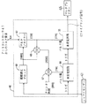
角度制御回路46の構造と動作は、図6により明確に示されている。図6は、周期測定ブロック60、マルチプライヤー62、エッジトリガされる第1の単安定回路(edge-triggered monostable circuit)64、エッジトリガされる第2の単安定回路66および2個の総和回路67および68から成る回路を開示している。図6が本発明に従う制御器の一般動作ブロックおよび特性を示しており、実際の制御器は図6のブロックによって表された機能を実行するため、アナログまたはデジタル回路を使用する。
【0047】
図6を参照して、周期測定ブロック60は、シャフトセンサー41の出力を受け取り、特定の時間の長さ、たとえば、シャフトセンサー41の出力の連続落下エッジ間の時間の長さ(すなわち、相周期の時間の長さ)に比例して変化する信号を発生する。したがって、周期測定ブロック60が発生した信号は、1つの相周期に必要な時間間隔に対応する信号である。
【0048】
上記の通り、単一パルス制御では、電圧の単一パルスが各相周期において伝導角の継続時間中、相巻線に印加される。本実施の形態の例では、伝導角は、ファイアリング信号がある時間によって決定される。一般には、相周期中に得られたファイアリング信号が長くなれば(すなわち、伝導角が大きくなれば)、トルクが大きくなる。したがって、トルク要求値信号が大きいほど、伝導角が大きくなり、ファイリング信号の継続時間が長くなる。
【0049】
図6に示す角度制御回路46では、ファイアリング信号(すなわち、伝導角)の継続時間は、測定ブロック60からの相周期の時間長さに対応する信号をP+I制御器47からのトルク要求値信号で乗じて、決定する。したがって、ファイアリング信号の継続時間は、トルク要求値信号にほぼ線形に比例する。図4の実施の形態では、P+I制御器47は、その出力が0〜0.5の値の信号であるように構成されている。ここで、0.5は100%のトルク要求値を表す。P+I制御器の出力が別の値を有する別の実施の形態も可能である。
【0050】
図4と6の実施の形態では、トルク要求値が最大であるとき、マルチプライヤー62の出力は完全な相周期に必要な時間間隔の半分の時間間隔を表す信号になる。相周期の半分が、相周期中相電流をゼロに低下できる理論的最大伝導角を表すので、マルチプライヤー62の出力は相周期の半分に限定される。トルク要求値信号が減少するにつれて、マルチプライヤー62の出力は完全な相周期に必要な時間間隔の一部である時間間隔に対応する。
【0051】
マルチプライヤー62の出力は、エッジトリガされる単安定回路66のパルス幅入力部に印加される。エッジトリガされる単安定回路66は、そのトリガ入力で起こった落下エッジに応答するパルス幅信号の値に比例する時間間隔中、ロジックハイ電圧パルスを発生するように構成されている。
【0052】
エッジトリガされる単安定回路66へのトリガ入力はエッジトリガされる単安定回路64の出力に接続される。単安定回路66と同様にエッジトリガされる単安定回路64は、そのトリガ入力で起こる落下エッジに応答するパルス幅入力での信号値に比例する時間間隔中、ロジックハイパルスを発生する。
【0053】
図6に示されるように、エッジトリガされる単安定回路64へのトリガ入力はシャフトセンサー41の出力に接続される。上記の通り、シャフトセンサー41は各相周期の開始時に落下エッジを発生する。シャフトセンサー41からの落下エッジは、シャフトセンサー41からの落下エッジ後、時々起こる落下エッジで終わる電圧パルスを単安定回路64に発生させる。相周期の開始時(落下エッジシャフトセンサー41によって定義される)と単安定回路64からの落下エッジ出力間の時間間隔は、単安定回路64のパルス幅入力部の信号に比例する。単安定回路64からの落下エッジ出力に応答して、単安定回路66はそのパルス幅入力(P+I制御器47からのトルク要求値信号に比例する)における信号に比例する出力ファイアリングパルスを発生する。
【0054】
図4と図6の実施の形態では、エッジトリガされる単安定回路64のパルス幅信号は、総和器67と68によって発生する。単安定回路66からのファイアリング角度パルスが終了する時点と、相周期の終了を表す時点間の時間の長さはここでは、ターンオフ時間と呼ばれる。ターンオフ時間に対応する信号は、ブロック60からの相周期の継続時間を表す信号とマルチプライヤー62からの伝導角の時間間隔を表す信号間の差に対応する第2の信号から、総和器67によって減算される。総和器67の出力は、相周期(シャフトセンサー41からの落下エッジによって定義される)の開始時と単安定回路66からのファイアリング信号の開始時間の時間間隔を表す。
【0055】
図4と図6の実施の形態では、ターンオフ時間は駆動系の最適性能に関して計算または経験的に決定できる。ターンオフ時間が一定でなく、回転子の角速度とともに変化する実施の形態も考えられる。さらに、ターンオフ時間が相周期の一定の部分である他の実施の形態も考えられる。このような実施の形態では、相周期の部分に対応する縮尺信号が相周期を表す信号によって乗じられ、図4と図6のターンオフ信号として使用できる信号を発生する。
【0056】
図7と図8は、回転子が一定の速度で回転し、縮尺トルク要求値信号が0.4であるとき、図4と図6の回路の動作を説明するのに使用できる種々の信号と信号レベルを示している。図8は図6と同一の角度制御器46を表し、信号レベルが加筆されている。図8では、この回路における信号に対応する(マイクロ秒表示の)時間間隔は、括弧[]で括られている。
【0057】
図7の波形70はシャフトセンサー41の出力を表す。図7に示す例では、回転子が毎分約16,600回転の一定速度で回転し、また波形70の落下エッジによって定義される相周期が1800マイクロ秒の時間間隔で起こることが仮定されている。したがって、図7と図8に示される例では、周期測定ブロック60の出力は、1800マイクロ秒に対応する信号になる。これは、周期測定ブロック60の出力が1800である図8に示されている。この例では、縮尺トルク要求値信号の値は0.4である。したがって、マルチプライヤー62の出力は(0.4×1800)に一致する720になり、この例の回転子速度とトルク要求値に関して720マイクロ秒の周期で、ファイアリング信号が発生しなければならないことを示す。すなわち、伝導角は720マイクロ秒の時間間隔に対応している。
【0058】
ファイアリング信号の長さ(または伝導角)を決定した後、ファイアリング信号の終了と相周期の終了間の時間の長さがターンオフ時間に等しい時点で、ファイアリング信号が終了するように、相周期においてファイアリング信号を開始するときを、本実施の形態の制御回路が決定しなければならない。これは、総和器67と68を使用して達成される。本実施の形態では、望ましいターンオフ時間が300マイクロ秒であると仮定されている。図8の例を参照し、必要な減算作業を実施すれば、単安定回路64のパルス幅信号は、相周期の開始時点とファイアリング信号の開始時点間の780マイクロ秒の遅れに対応する780である。
【0059】
図7の波形72は、前の例の場合の単安定回路66からのファイアリング信号を示す。波形70を見れば判るように、相周期の開始時点は落下エッジ71で示される。落下エッジ71は、単安定回路64をトリガし、相周期の開始時点後780マイクロ秒で落下エッジが起こるパルスを発生する。単安定回路64によって発生する落下エッジは単安定回路66をトリガし、720マイクロ秒間信号(ファイアリング信号)を発生する。ファイアリング信号の開始時点は、図7の波形72の上昇エッジ73で表わされる。単安定回路66へのパルス幅入力が720マイクロ秒の伝導角周期に一致するので、ファイアリング信号は720マイクロ秒後、1800マイクロ秒の相周期の終了前300マイクロ秒の時点で終了する。上記の通り、この例では、300マイクロ秒が望ましいターンオフ時間である。
【0060】
図4、図6、図7および図8がディスクリート総和器、単安定回路および他の回路の使用を示しているが、本発明は、1個以上のASIC、マイクロ制御器またはマイクロプロセッサーを使用する制御器で実施できる。たとえば、図4の点線内のボックスに含まれる全ての回路は、ハードウェアとソフトウェアによってMotorola 68HC11のような単一マイクロプロセッサーで実施できる。このような実施の形態では、マイクロ制御器(ポートA)のオンチップメインタイマーシステムブロックは、ファイアリング信号を発生するエッジ・トリガされる単安定回路64と66として、さらにマルチプレクサー20として作用するようにプログラムできる。
【0061】
Motorolaマイクロプロセッサーを使用するとき、ブロック60の相周期測定機能は、タイマーポートの入力捕捉機能を使用して実行できる。単安定性能を有効にするため、ターンオン時間と伝導時間を計算し、タイマーポートに負荷できる。デジタルシステムの数的オーバフローを回避するため、相周期とトルク要求値信号は、乗算の最大縮尺結果が実際の相周期の半分であるような縮尺でなければならない。上記の通り、この縮尺によって、伝導角が図9に示すシステムに関する理論的に最大の連続/不連続電流境界条件に限定され、ソフトウェアで実行できる。
【0062】
マイクロ制御器を使用するとき、マイクロ制御器による固定時間の割り込みによって設定される固定時間間隔で速度エラーを計算し、そしてトルク要求値を更新するため、比例・積分アルゴリズムを1周期基準で速度エラーに応用するソフトウェアでのみ、P+I制御器47を実現できる。
【0063】
マイクロ制御器またはマイクロ制御器で本発明の方法と回路を実現するソフトウェアルーチンは、この開示内容を利用して当業者であれば、開発できる。
【0064】
ターンオンおよびターンオフ角度で定義される伝導角によって単一電圧パルスの印加が定義される単一パルス制御に加えて、単一電流パルスがターンオン角度、フリーホイール(free wheel)角度およびターンオフ角度によって定義される制御器を実現するため、本発明を利用できる。
【0065】
当業者が理解するように、フリーホイーリングを利用するとき、一般に相巻線に関連して2個のスイッチングデバイスがあり、各相周期を次のように分割できる。すなわち、(i)電圧を相巻線に印加しない間隔(すなわち、両方の電力スイッチがオフで、リターンダイオードが非伝導状態である)、(ii)DCリンク電圧が相巻線に印加される間隔(すなわち、両方の電力デバイスがオンである)、(iii)相巻線の電流がスイッチの1個とダイオードの1個によって「フリーホイーリング」にできる間隔(すなわち、1個の電力デバイスがオンし、1個のダイオードが伝導している)、(iv)利用できるDC電圧の負値が相巻線に印加される間隔(すなわち、両方の電力スイッチがオフで、リターンダイオードが伝導している)である。
【0066】
フリーホイーリングを実現する典型的な回路配置と、このような回路からの典型的な制御信号は、図9と図10に示される。フリーホイーリング配置では、典型的には、上部デバイス80と下部デバイス82の2個の電力デバイスがある。また、各相巻線と関連して2個のリターンダイオード84と86もある。図10は、フリーホイーリングを使用する相周期でのスイッチングデバイス80と82のファイアリング信号を示す。図10に示されるように、両方のスイッチングデバイスがオンで、利用できるDCリンク電圧が相巻線に印加される初期周期がある。それから、スイッチングデバイスの1個(ここでは、デバイス82)がオフである「フリーホイーリング」周期と両方のデバイスがオフである周期がある。フリーホイーリング周期では、電流はデバイス80、ダイオード84および相巻線によって形成されるループを自由に流れる。
【0067】
図11と図12は、フリーホイーリングを利用できる本発明に従う角度制御器90の一例を示す。図11の制御器は、エッジトリガされる単安定回路92と総和器94が追加される主要な相違を別にすれば、図4の制御器と同一である。追加のエッジ・トリーガされる単安定回路92と総和器94は下部スイッチングデバイス82用の別個のファイアリング信号を発生する。図11のこの実施の形態では、望ましいフリーホイーリング周期の継続時間に対応する信号は、総和器94への1つの出力として印加される。この値は望ましい伝導角の時間間隔を表す信号から減算され、単安定回路92用のパルス幅信号を発生する。図4の回路と関連して記載した前記と同じ様式で、総和器94とエッジトリガされる単安定回路92は、フリーホイーリングを可能にするように下部スイッチングデバイス82を制御する。
【0068】
1800マイクロ秒の相周期、300マイクロ秒のターンオフ時間、0.4の縮尺トルク要求値および100マイクロ秒のフリーホイーリング周期で作動する電動機の例の場合に、図11の制御器によって発生する信号は、図8の場合のように括弧を使用して図11に示されている。
【0069】
図11の実施の形態では、フリーホイール時間は、制御器と電動機システムの騒音を最小限にするため選択されている固定値である。この実施の形態では、フリーホイール時間は、切り換えリラクタンス電動機の固有共鳴に基づいて選択できるか、フリーホイール時間を調整して、システムの騒音をモニターして、最小の騒音を発生するフリーホイール時間を決定して、経験的に確定できる。フリーホイール時間を制御でき、またこの時間がたとえば、電動機の速度または他の作動パラメータとともに変動する他の実施の形態も考えられる。なお、フリーホイーリングを開始するのに使用するスイッチングデバイスが上部デドイスと下部デバイス間で交代する他の実施の形態も考えられる。電力デバイス間の熱損失を均衡化し、制御器の設計を容易にするため、過去には、交代フリーホイーリング方法が採用された。この方法は、マルチプレクサーまたは同様なデバイスに図11の2つのファイアリング信号を送り、2個のスイッチングデバイスに信号を交代に送ることによって実施できる。
【0070】
上記の例と説明は、制御器が連結されている切り換えリラクタンス機械が電動機として機能する本発明の制御器の作動に関するものである。また、切り換えリラクタンス機械が発電機として作動するときにも、本発明の制御器を使用できる。切り換えリラクタンス機械が発電機として作動するとき、制御回路のタイミングは、固定子極と並んでいる回転子の極間軸に対応するシャフトセンサー41からの信号のエッジからトリガしなければならない。図5に示すように、RPT信号の上昇エッジを使用してマーク領域:スペース領域比が1のRPTを利用するとき、この状態を都合よく達成できる。シャフトセンサー41の上昇エッジから回路をトリガすることによって、発電機として作動する機械でこの制御回路を使用できる。当業者が理解するように、RPT信号の他の操作方法も可能である。すなわち、相シフトするためにパルス列に半周期を追加するか、適切な角度分だけ回転子シャフト上でRPTを移動できるだろう。したがって、本発明の制御回路は、機械作動のトルク/速度平面の4象限全部で使用できる。
【0071】
本発明は上記の実施の形態と関連して説明されたが、当業者が認識するように、本発明から逸脱せずに多くの変更を実施できる。したがって、幾つかの実施の形態に関しての上記の説明は例示であり、制限を意図としていない。
【0072】
【発明の効果】
以上のように本発明によれば、リラクタンス電動機制御器において、伝導角に対応し、トルク要求値とともに変化し、実際の回転子位置に同期する単一パルスファイアリング信号を発生するエッジトリガされた単安定回路を使用して電動機を制御するので、制御法則表(回路)を装備する必要がなく、制御器のコストを押さえ、また電動機の負荷トルクと速度(回転)の急激な変化にも対処して制御できる。
【図面の簡単な説明】
【図1】トルク制御方法として電流チョッピングを使用したときの切り換えリラクタンス電動機の相電流を一般的に示す図である。
【図2】単一パルス電圧制御に従って作動する切り換えリラクタンス電動機の相電流波形例の図である。
【図3】制御法則表を利用した切り換えリラクタンス電動機のための可変速制御器の略式ブロック図である。
【図4】本発明に従う単相切り換えリラクタンス電動機用の可変速制御器の略式ブロック図である。
【図5】本発明を実施するため使用できる回転子位置トランスジューサの出力を示す図である。
【図6】本発明に従う角度制御器の作動ブロック図と特性図である。
【図7】図6の角度制御器の動作状態の信号を示す図である。
【図8】図6の角度制御器のブロック図であり、主要要素の信号レベルも示してある。
【図9】本発明に従う角度制御器でフリーホイーリングを実施するため使用できる電力回路を示すブロック図である。
【図10】図8の回路に含まれるスイッチングデバイスから発生されるファイリング信号例を示す図である。
【図11】本発明に従うフリーホイーリング角度制御器のための制御回路を示すブロック図である。
【図12】図11の回路で発生される信号例を示す図である。
【符号の説明】
30,40 制御器
31 エラー検知器
32 制御法素
41 シャフトセンサー
42 速度測定ブロック
43 チョッピング電流コンパレータ
44 ANDゲート
45 マルチプレクサー
46 角度制御回路
47 P+I制御器
60,60′ 周期測定ブロック
62,62′ マルチプライヤー
64,64′,66,66′,92 エッジ−トリガ単安定回路
67,67′68,68′94 総和器[0001]
BACKGROUND OF THE INVENTION
The present invention relates to a control system for a switched reluctance machine. In particular, the present invention relates to a switched reluctance machine control circuit and control method that do not require a control law table. The circuit and method of the present invention can be applied to all four quadrants of the torque / speed plane of operation.
[0002]
[Prior art]
Electric motors convert electrical energy into mechanical energy and perform work. The motor operates by applying a voltage to one or more windings to energize the windings and generate a reluctance magnetic field. The pulling mechanical force caused by the magnetic field moves the rotor of the motor. The efficiency of the motor is determined in part by the timing and extent of applying voltage to the motor. The timing at which the voltage is applied is particularly important for switched reluctance motors.
[0003]
Historically, switched reluctance motors were thought to be unable to compete effectively with other types of motors. Recently, however, motor designs and how to use electronically controlled switching have been well understood, producing rugged switched reluctance drives capable of high levels of performance over a wide range of sizes, power, and speeds. The term “motor” is used herein, but as those skilled in the art will appreciate, the term also includes the same machine in power generation mode unless otherwise distinguished.
[0004]
A switched reluctance motor is generally structured such that a rotating part (referred to as a rotor) is assembled without a conductive winding or permanent magnet, and a fixed part (referred to as a stator) is energized. Typically, multiple pairs of stator poles that are diametrically opposed can be connected in series or in parallel to form one phase of a possible multiphase switched reluctance motor. When a voltage is applied to each phase winding in a preset sequence synchronized with the angular position of the rotor, an electric torque is generated, and when the rotor and stator approach each other, the attractive magnetic force is drawn between both poles. Will occur. Similarly, if a voltage pulse is applied to the part of the cycle where the poles are separated from each other, power generation occurs.
[0005]
General theory about the design and operation of switched reluctance motors is well known, for example, “Characteristics, Design and Application of Switched Reluctance Motors and Drives” by Stefenson and Blake (June 21-23, 1993, German New Nberg's PCIM '93 conference / exhibition).
[0006]
Various strategies have been proposed in the past to control switched reluctance motors as part of a comprehensive variable speed drive system. In general, such strategies fall into two general groups. That is, a system that controls the current over a fixed rotation angle of the rotor and a system that controls the voltage over a variable rotation angle of the rotor. The present invention relates to a system using voltage control.
[0007]
In general, the “phase period” used here is the position of the rotor when the first rotor pole is perfectly aligned with the focal stator pole and the position when the adjacent rotor pole is aligned with the stator pole. It means the period between rotor positions. There are a number of phase periods for each revolution of the rotor, depending on the number of rotor and stator poles.
[0008]
Typically, the current control system controls the torque of the switched reluctance motor by controlling the magnitude of the phase winding current during each phase period. In known switched reluctance motor systems, the motor firing (automatic start) controller causes the phase winding current to drop to zero at or near the point where the rotor pole is perfectly aligned with the focal stator pole. Are arranged as follows. This is because the current in the phase winding after the point where the rotor pole is aligned with the focal stator pole produces a braking torque that is generally undesirable in motor operation.
[0009]
When stopped and at low speeds, the torque can be controlled by changing the current in this phase during the phase period that produces the desired torque polarity. This can be accomplished by chopping the current using a current reference that includes phase current feedback or by pulse width modulation (PWM) voltage control. Such a control strategy is generally understood, but will be briefly described below to assist in the subsequent description of the invention.
[0010]
FIG. 1 generally illustrates a typical motor phase winding current waveform that is in the low speed range when using chopping. As shown in FIG. 1, the current increases until it reaches the current reference to be chopped, i.e. no further increase is prevented by the controller. The current then decreases to a low control level where the voltage is reapplied and the current increases again. This process is repeated until the end of the phase period.
[0011]
As the angular velocity of the motor increases, a point is reached where there is insufficient time to generate two or more “choppings” of current during each phase period. Therefore, at such speeds, both chopping strategy and pulse width modulation are not effective. At such speeds, the motor torque is typically controlled by controlling the position and duration of the voltage pulses applied to the windings during the phase period. Since a single pulse of voltage is applied during each phase period, this form of control method is called "single pulse control".
[0012]
FIG. 2 shows a current waveform example of the phase current in the motor operating state according to the single pulse control. In single pulse control, the torque level depends on the magnitude and shape of the voltage pulse, which generally depends on the following factors: That is, the angular speed of the rotor, the voltage is applied to the phase winding, the point during rotation of the rotor (called “turn-on angle”), the application of voltage to the winding is stopped, the rotor is rotating The time (referred to as “turn-off angle”) and the magnitude of the voltage applied to the phase winding. The turn-on and turn-off angles determine the “conduction angle”. The conduction angle is the angular distance between the turn-on angle and the turn-off angle. FIG. 2 generally shows the approximate location of turn-on and turn-off angles and the duration of the conduction angle in the waveform example.
[0013]
Assuming a constant DC link voltage, the relationship between torque demand and appropriate turn-on and turn-off angles for each motor speed cannot be defined by simple equations. In known switched reluctance motor systems, this complex relationship is typically implemented using circuitry that stores signals representing the relationship between motor turn-on and turn-off angles, as well as speed and torque demands. ing. This type of circuit is usually referred to as a “control law table”.
[0014]
In many known controllers for switched reluctance motors, the control law table consists of circuitry that includes turn-on and turn-off angle information for various combinations of rotor speed and torque requirements. In most systems, the information stored in the control law table “characterizes” to determine the appropriate turn-on and turn-off angles required to generate torque demands for a number of different rotor speeds. Obtained empirically by a process commonly known as: Information gained from experience is sometimes stored in a control law table, along with information about untested speed and torque requirements interpolated from the information gained from experience.
[0015]
FIG. 3 is a simplified block diagram of an example variable speed controller for single pulse control of the type using a control law table. As shown, the
[0016]
The torque demand signal and the feedback signal representing the rotor angular velocity are provided to a circuit containing the control law table 32, which generates signals representing the appropriate turn-on and turn-off angles. Information regarding the corresponding conduction angle is provided to a
[0017]
[Problems to be solved by the invention]
One drawback of controllers that use control law tables is that they need to be equipped with a control law circuit. In particular, the digital memory normally used to store control law information is relatively expensive and increases the overall cost of the control system. Furthermore, using the control law table requires a new motor and a process for characterizing the motor for each controller, which increases the cost and time required to develop a new control system. Furthermore, another drawback of the control law table is that discretisation occurs. In other words, the control law table can store conduction angle information only for a specific number of speed / torque demand value combinations. If the actual speed / torque demand value combination is different from that contained in the control law table, the control system will normally provide conduction angle information for the speed / torque demand value closest to the actual speed / torque demand point. provide. As a result, conduction angle information that is not necessarily optimal for each speed / torque required value point is used.
[0018]
In the past, several approaches have been attempted to provide a controller for switched reluctance motors that does not rely on costly control schemes. As discussed below, most of the known methods that replace the control law table have significant drawbacks.
[0019]
For example, A.I. Weller and P. Travinsky has a simple angle control in the “Low Power Switching Reluctance Motor (<1 kW)” Proceedings of the 4th European Power Electronics Application Conference (EPE'91) (Florence, Italy, pp 1-7, September 1991) A vessel is proposed. In the controller proposed here, turn-on and turn-off angles are programmed into the controller to vary with speed, not torque. Since the torque information is not considered in the generation of the conduction angle signal in this system, the above control system will not operate smoothly over a wide operating range. Furthermore, in the disclosed system, the velocity loop can become unstable.
[0020]
Another alternative to using a large, costly control law table is described by Boss et al., “Microcontroller for Switching Reluctance Motors” IA-22, July / August 1986, p. 708-715. The controller disclosed by Boss is equipped with a relatively small, schematic control law table, and the actual conduction angle information is calculated in real time by interpolation estimation. This proposed method does not require a large, costly control law table, but cannot cope with the computational power and complexity that is greatly increased in the control system. In addition, because of the additional time associated with interpolation estimation, such methods cannot adequately cope with sudden changes in load torque and speed.
[0021]
[Means for Solving the Problems]
The present invention provides a system and control method for controlling a switched reluctance machine within a single pulse range without using large, costly control law tables and complex computational strategies.
The control system and method of the present invention provides a simple system for obtaining a firing pulse from rotor position information using a delay that triggers the firing pulse.
[0022]
The present invention relates to a control system for a switched reluctance machine including a rotor, a stator, and at least one phase winding.
Position determining means for obtaining a position signal indicating the rotor position;
Means for generating a machine torque demand signal;
Means for generating a first duration value of a firing pulse from the torque demand value signal;
Means for generating a turn-off time value;
Means for generating a second duration value of delay that is the difference between the phase period and the combination of the first duration and turn-off time of the firing pulse;
Delay means that can be triggered by a position signal to generate a delayed pulse having the second duration after a turn-off time;
Firing pulse means capable of triggering at the end of a delay pulse to generate the firing pulse having the first duration;
Means for energizing at least one phase winding in accordance with the firing pulse.
The present invention also includes a speed measuring means for obtaining a speed signal indicating the speed of the rotor,
Requesting means for generating the torque demand value signal proportional to the comparison of the speed signal and the speed demand value signal;
The means for generating the first duration value includes means for generating a phase period signal indicating the duration of the phase period, wherein the first duration is a phase period proportional to the magnitude of the torque request value signal. It is a part.
Further, the invention is characterized in that the speed measuring means is arranged to respond to a position signal in order to obtain a speed signal.
Further, the present invention is characterized in that the requesting means includes a comparator arranged to receive the speed signal and the speed request value signal and generate an error signal output from the comparison.
The invention also includes an error compensator arranged to receive the error signal and generate a torque demand value signal in response thereto.
According to the present invention, the error compensator includes a proportional / integral controller.
The present invention is also arranged such that the first comparator generates a first difference signal indicative of the difference between the phase period and the first duration,
The means for generating the second duration value is arranged to generate a second difference signal indicative of a difference between the first difference signal and the turn-off signal at a predetermined duration from the start of the phase period. A second comparator to be
A delay means is responsive to the position signal to generate a delayed pulse having a second duration determined by the second difference signal;
The firing pulse means is responsive to the end of the delayed pulse and generates a firing pulse having a first duration.
The present invention is characterized in that the means for generating the first duration value includes a calculation means for calculating the firing pulse duration from the phase period signal and the torque request value signal.
Further, the present invention is characterized in that the calculating means includes a multiplier arranged to receive the phase period signal and the torque request value signal and generate a firing pulse as a product of the magnitudes of the two signals. .
The invention is also characterized in that the firing pulse means is operable to generate a firing pulse having a maximum duration of half the phase period indicated by the phase period signal.
The invention also includes a multiplexer that receives the firing pulse and the position signal and is arranged to time the firing pulse according to the rotor position.
The present invention also includes a control means having a reference current input and a phase current feedback input and operable to generate a control signal in a chopping mode;
And an AND gate arranged to receive the output of the control means and the firing pulse,
The reference current input can be set to overcurrent protection level and the firing pulse can be used to control the machine,
It is characterized in that the control signal can be used to set the low level and control the machine in chopping mode.
The present invention also provides a control method for a switched reluctance machine including a rotor, a stator, and at least one phase winding.
Determining the position of the rotor and generating a position signal;
Generating a machine torque demand value signal;
Generating a first duration value of a firing pulse from the torque demand value signal;
Generating a turn-off time value;
Generating a second duration value of delay that is the difference between the phase period and the combination of the first duration and turn-off time of the firing pulse;
Generating a delayed pulse having a second duration after the turn-off time and triggered by the position signal;
Generating a firing pulse having a first duration and triggered at the end of the delay pulse;
Energizing at least one phase winding in accordance with a firing pulse. A method for controlling a switched reluctance machine.
The invention also includes the step of determining the speed of the rotor;
Comparing the rotor speed and the required speed to obtain a torque request value signal;
Determining a phase period with respect to the velocity and generating a phase period signal;
Generating a firing pulse duration as part of a phase period proportional to the magnitude of the torque demand value signal.
The invention is also characterized in that the speed of the rotor is obtained from the determination of the position of the rotor.
The present invention is also characterized in that a torque request value signal is generated to compare and compensate the rotor speed and the required speed to reduce the difference between the speed and the required speed.
According to the present invention, the firing pulse compares the phase period signal with the firing pulse to generate a first difference signal, and the first difference signal is a turn-off signal having a predetermined duration from the start of the phase period. And the second duration is determined by the second difference signal, and the firing pulse is started at the trailing edge of the delayed pulse having a duration determined by the firing signal It is characterized by.
Further, the present invention is characterized in that a firing signal is generated by multiplying a phase period signal by a torque request value signal.
The invention is also characterized in that the firing pulse has a maximum duration of half the phase period.
The invention also sets the reference current input to the controller to a chopping level and controls the machine in chopping mode, or sets the reference current level to a higher level and sets the controller output to a firing pulse. And AND gate to control the machine in single pulse mode.
[0023]
According to the present invention, the aforementioned drawbacks of known switched reluctance motor controllers correspond to the conduction angle, increase as the torque demand increases, and output with a pulse width that is synchronized to the actual rotor position. It is overcome by using an edge-triggered monostable circuit comprising: Here, the pulse width of the monostable circuit corresponding to the conduction angle is not controlled as a parameter from the control law table.
[0024]
Other aspects and advantages of the present invention will become apparent upon reading the detailed description of the embodiments with reference to the accompanying drawings. In the drawings, the same reference numerals denote the same parts.
[0025]
DETAILED DESCRIPTION OF THE INVENTION
Unlike known controllers for switched reluctance motors, the present invention eliminates the need for large, costly control law tables.
[0026]
In general, the present invention implements a variable speed controller that receives a speed command signal and an actual speed signal and generates a torque demand value signal. The torque demand signal is then used to generate a conduction angle signal that represents the angular period during which voltage is applied to the corresponding phase winding. Information about the angular velocity and position of the rotor is then used to set the turn-on and turn-off angles so that a voltage is applied to the phase winding during the desired portion of the phase period.
[0027]
For ease of explanation, the following description is limited to single phase switched reluctance motors. As will be appreciated by those skilled in the art, the present invention is also applicable to multiphase switched reluctance machines. In order to apply the present invention to multiphase machines, it is only necessary to equip each phase period with the additional circuitry necessary to identify the appropriate phase winding to be energized. Given the disclosure of the present invention, the structure of a multi-phase switched reluctance machine embodying the present invention can be readily understood by those skilled in the art and will not be described in detail here.
[0028]
FIG. 4 is a block diagram of a variable speed controller for a single phase switched reluctance machine according to the present invention. The controller of the present invention can be applied to many types of switched reluctance machines, and the fabrication of such machines can be performed according to known methods and techniques.
[0029]
The
[0030]
FIG. 5 shows the output of the RPT that constitutes the
[0031]
The RPT comprising the
[0032]
As can be seen by reviewing FIG. 4, the
[0033]
As described above, current chopping can be used to control the torque of the switched reluctance motor at low speed. FIG. 4 shows an example of a chopping circuit that can be used in a controller according to the present invention.
[0034]
Referring to FIG. 4, a chopping
[0035]
In the embodiment of FIG. 4, the second input to AND gate 44 is the output of
[0036]
When it is determined from the output of the
[0037]
In an example where the
[0038]
When high speed and single signal pulse control is required, the control signal applied to the
[0039]
When utilizing single pulse voltage control, the
[0040]
As described above, when it is determined from the rotor speed indicated by the output of the
[0041]
In the present invention, the torque request value signal is generated by using a compensator, for example, a PI (proportional / integral)
[0042]
As can be seen from FIG. 4, the circuit compares the actual speed of the rotor with the desired speed of the
[0043]
The P +
[0044]
As those skilled in the art will appreciate, the compensator could be implemented as a proportional, proportional-integral-derivative (PPID), sliding mode or fuzzy logic compensator without departing from the invention.
[0045]
The output of the P +
[0046]
The structure and operation of the
[0047]
Referring to FIG. 6, the
[0048]
As described above, in single pulse control, a single pulse of voltage is applied to the phase winding for the duration of the conduction angle in each phase period. In the example of the present embodiment, the conduction angle is determined by the time at which the firing signal is present. In general, the longer the firing signal obtained during the phase period (ie the greater the conduction angle), the greater the torque. Therefore, the larger the torque request value signal, the larger the conduction angle and the longer the filing signal duration.
[0049]
In the
[0050]
In the embodiment of FIGS. 4 and 6, when the torque demand is maximum, the output of
[0051]
The output of
[0052]
The trigger input to the edge triggered
[0053]
As shown in FIG. 6, the trigger input to the edge triggered
[0054]
In the embodiment of FIGS. 4 and 6, the edge-triggered
[0055]
In the embodiment of FIGS. 4 and 6, the turn-off time can be calculated or empirically determined for optimum performance of the drive train. An embodiment in which the turn-off time is not constant and varies with the angular velocity of the rotor is also conceivable. Furthermore, other embodiments are contemplated where the turn-off time is a constant part of the phase period. In such an embodiment, the scale signal corresponding to the phase period portion is multiplied by the signal representing the phase period to generate a signal that can be used as the turn-off signal of FIGS.
[0056]
7 and 8 show various signals that can be used to explain the operation of the circuits of FIGS. 4 and 6 when the rotor rotates at a constant speed and the scale torque demand signal is 0.4. The signal level is shown. FIG. 8 shows the
[0057]
A
[0058]
After determining the length (or conduction angle) of the firing signal, the phase is such that the firing signal ends when the length of time between the end of the firing signal and the end of the phase period equals the turn-off time. The control circuit of this embodiment must determine when to start the firing signal in the period. This is accomplished using
[0059]
A
[0060]
Although FIGS. 4, 6, 7 and 8 illustrate the use of discrete summers, monostable circuits and other circuits, the present invention uses one or more ASICs, microcontrollers or microprocessors. Can be implemented with a controller. For example, all the circuits contained in the box within the dotted line in FIG. 4 can be implemented in hardware and software on a single microprocessor such as a Motorola 68HC11. In such an embodiment, the on-chip main timer system block of the microcontroller (port A) acts as an edge-triggered
[0061]
When using a Motorola microprocessor, the phase period measurement function of
[0062]
When using a microcontroller, calculate the speed error at a fixed time interval set by a fixed time interrupt by the microcontroller, and update the torque request value, the proportional and integral algorithm speed error on a cycle basis The P +
[0063]
Microcontrollers or software routines that implement the methods and circuits of the present invention on the microcontroller can be developed by those skilled in the art using this disclosure.
[0064]
In addition to single pulse control where the application of a single voltage pulse is defined by the conduction angle defined by the turn-on and turn-off angles, a single current pulse is defined by the turn-on angle, free wheel angle and turn-off angle. The present invention can be used to implement a controller.
[0065]
As those skilled in the art will appreciate, when utilizing freewheeling, there are generally two switching devices associated with the phase winding, and each phase period can be divided as follows. (I) the interval at which no voltage is applied to the phase winding (ie, both power switches are off and the return diode is non-conductive); (ii) the interval at which the DC link voltage is applied to the phase winding. (Ie, both power devices are on), (iii) the interval at which the phase winding current can be “freewheeled” by one of the switches and one of the diodes (ie, one power device is on) And (iv) the interval at which the negative value of the available DC voltage is applied to the phase winding (ie, both power switches are off and the return diode is conducting) ).
[0066]
Typical circuit arrangements for implementing freewheeling and typical control signals from such circuits are shown in FIGS. In a freewheeling arrangement, there are typically two power devices, an
[0067]
11 and 12 show an example of an angle controller 90 according to the present invention that can utilize freewheeling. The controller of FIG. 11 is the same as the controller of FIG. 4 except for the main difference in that an edge-triggered
[0068]
The signal generated by the controller of FIG. 11 for the example of an electric motor operating with a phase period of 1800 microseconds, a turn-off time of 300 microseconds, a scale torque demand of 0.4 and a freewheeling period of 100 microseconds. Is shown in FIG. 11 using parentheses as in FIG.
[0069]
In the embodiment of FIG. 11, the freewheel time is a fixed value that is selected to minimize noise in the controller and motor system. In this embodiment, the freewheel time can be selected based on the intrinsic resonance of the switched reluctance motor, or the freewheel time can be adjusted to monitor the system noise and reduce the freewheel time to generate the minimum noise. Can be determined and determined empirically. Other embodiments are contemplated which can control the freewheel time and this time varies with, for example, motor speed or other operating parameters. Other embodiments in which the switching device used to initiate freewheeling alternates between the upper device and the lower device are also conceivable. In the past, alternate freewheeling methods have been employed to balance heat loss between power devices and to facilitate controller design. This method can be implemented by sending the two firing signals of FIG. 11 to a multiplexer or similar device and alternately sending the signals to two switching devices.
[0070]
The above example and description relate to the operation of the controller of the present invention in which the switched reluctance machine to which the controller is coupled functions as an electric motor. The controller of the present invention can also be used when the switched reluctance machine operates as a generator. When the switched reluctance machine operates as a generator, the timing of the control circuit must be triggered from the edge of the signal from the
[0071]
Although the present invention has been described in connection with the above embodiments, many modifications can be made without departing from the invention, as those skilled in the art will recognize. Accordingly, the above description of some embodiments is illustrative and not intended to be limiting.
[0072]
【The invention's effect】
As described above, according to the present invention, in a reluctance motor controller, an edge-triggered signal is generated that generates a single pulse firing signal corresponding to a conduction angle, changing with a torque request value, and synchronizing with an actual rotor position. Since the motor is controlled using a monostable circuit, it is not necessary to equip a control law table (circuit), control the cost of the controller, and cope with sudden changes in the load torque and speed (rotation) of the motor Can be controlled.
[Brief description of the drawings]
FIG. 1 is a diagram generally showing phase currents of a switched reluctance motor when current chopping is used as a torque control method.
FIG. 2 is a diagram of an example phase current waveform of a switched reluctance motor that operates according to single pulse voltage control.
FIG. 3 is a schematic block diagram of a variable speed controller for a switched reluctance motor utilizing a control law table.
FIG. 4 is a schematic block diagram of a variable speed controller for a single phase switched reluctance motor according to the present invention.
FIG. 5 is a diagram showing the output of a rotor position transducer that can be used to implement the present invention.
FIG. 6 is an operation block diagram and a characteristic diagram of an angle controller according to the present invention.
7 is a diagram showing a signal of an operation state of the angle controller of FIG. 6. FIG.
FIG. 8 is a block diagram of the angle controller of FIG. 6 showing the signal levels of the main elements.
FIG. 9 is a block diagram illustrating a power circuit that can be used to perform freewheeling with an angle controller in accordance with the present invention.
10 is a diagram showing an example of a filing signal generated from a switching device included in the circuit of FIG.
FIG. 11 is a block diagram showing a control circuit for a freewheeling angle controller according to the present invention.
12 is a diagram illustrating an example of signals generated by the circuit of FIG.
[Explanation of symbols]
30, 40 controller
31 Error detector
32 Control Element
41 Shaft sensor
42 Speed measurement block
43 Chopping current comparator
44 AND gate
45 Multiplexer
46 Angle control circuit
47 P + I controller
60,60 'period measurement block
62, 62 'multiplier
64, 64 ', 66, 66', 92 Edge-trigger monostable circuit
67, 67'68, 68'94
Claims (20)
回転子位置を示す位置信号を得るための位置確定手段(41)と、
機械トルク要求値信号を発生するための手段(47)と、
前記トルク要求値信号からファイアリングパルスの第1の継続時間の値を発生する手段と、
ターンオフ時間の値を発生するための手段と、
相周期とファイアリングパルスの第1の継続時間およびターンオフ時間の組合せとの間の差である遅延の第2の継続時間の値を発生する手段(67,68)と、
ターンオフ時間後、前記第2の継続時間を有する遅延パルスを発生するために位置信号によってトリガできる遅延手段(64)と、
前記第1の継続時間を有する前記ファイアリングパルスを発生するために遅延パルスの終了でトリガできるファイアリングパルス手段(66)と、
前記ファイアリングパルスに従って少なくとも1つの相巻線を付勢する手段とを含むことを特徴とする切り換えリラクタンス機械用制御システム。In a control system for a switched reluctance machine comprising a rotor, a stator and at least one phase winding,
Position determining means (41) for obtaining a position signal indicating the rotor position;
Means (47) for generating a machine torque demand value signal;
Means for generating a first duration value of a firing pulse from the torque demand value signal;
Means for generating a turn-off time value;
Means (67, 68) for generating a second duration value of delay that is the difference between the phase period and the combination of the first duration and turn-off time of the firing pulse;
Delay means (64) that can be triggered by a position signal to generate a delayed pulse having said second duration after a turn-off time;
Firing pulse means (66) that can be triggered at the end of a delay pulse to generate the firing pulse having the first duration;
Means for energizing at least one phase winding in accordance with the firing pulse, the control system for a switched reluctance machine.
速度信号と速度要求値信号との比較に比例する、前記トルク要求値信号を発生する要求手段(47,48)とを含み、
前記第1の継続時間の値を発生する手段(60,62)は、相周期の継続時間を示す相周期信号を発生する手段(60)を含み、第1の継続時間はトルク要求値信号の大きさに比例する相周期の部分であることを特徴とする請求項1記載の切り換えリラクタンス機械用制御システム。Speed measuring means (42) for obtaining a speed signal indicative of the speed of the rotor;
Request means (47, 48) for generating said torque request value signal, which is proportional to the comparison between the speed signal and the speed request value signal;
The means (60, 62) for generating the value of the first duration includes means (60) for generating a phase period signal indicating the duration of the phase period, and the first duration is a value of the torque request value signal. 2. A control system for a switched reluctance machine according to claim 1, wherein the control system is a part of a phase period proportional to the magnitude.
第2の継続時間の値を発生する手段が、相周期の開始からの予め定める継続時間における第1の差信号とターンオフ信号との間の差を示す第2の差信号を発生するように配置される第2のコンパレータ(67)を含み、
遅延手段(64)が、位置信号に応答し、第2の差信号によって決まる第2の継続時間を有する遅延パルスを発生し、
ファイアリングパルス手段(66)が、遅延パルスの終了に応答し、第1の継続時間を有するファイアリングパルスを発生することを特徴とする請求項2〜6のいずれかに記載の切り換えリラクタンス機械用制御システム。A first comparator (68) is arranged to generate a first difference signal indicative of a difference between the phase period and the first duration;
The means for generating the second duration value is arranged to generate a second difference signal indicative of a difference between the first difference signal and the turn-off signal at a predetermined duration from the start of the phase period. A second comparator (67)
A delay means (64) is responsive to the position signal to generate a delayed pulse having a second duration determined by the second difference signal;
7. The switched reluctance machine according to claim 2, wherein the firing pulse means (66) generates a firing pulse having a first duration in response to the end of the delay pulse. Control system.
さらに、制御手段の出力とファイアリングパルスとを受け取るように配置されたANDゲート(44)とを含み、
基準電流入力は、過電流保護レベルに設定し、機械を制御するためにファイアリングパルスを使用でき、
低レベルに設定し、チョッピングモードで機械を制御するために制御信号を使用することができることを特徴とする請求項1〜11のいずれかに記載の切り換えリラクタンス機械用制御システム。Control means (43) having a reference current input and a phase current feedback input and operable to generate a control signal in a chopping mode;
And an AND gate (44) arranged to receive the output of the control means and the firing pulse,
The reference current input can be set to overcurrent protection level and the firing pulse can be used to control the machine,
12. A control system for a switched reluctance machine according to any of the preceding claims, characterized in that the control signal can be used to set the low level and control the machine in a chopping mode.
回転子の位置を決定して、位置信号を発生するステップと、
機械トルク要求値信号を発生するステップと、
該トルク要求値信号からファイアリングパルスの第1の継続時間の値を発生するステップと、
ターンオフ時間の値を発生するステップと、
相周期とファイアリングパルスの第1の継続時間およびターンオフ時間の組合せとの間の差である遅延の第2の継続時間の値を発生するステップと、
ターンオフ時間後、第2の継続時間を有し、位置信号によってトリガされる遅延パルスを発生するステップと、
第1の継続時間を有し、遅延パルスの終了でトリガされるファイアリングパルスを発生するステップと、
ファイアリングパルスに従って少なくとも1つの相巻線を付勢するステップとを含むことを特徴とする切り換えリラクタンス機械の制御方法。In a control method for a switched reluctance machine comprising a rotor, a stator, and at least one phase winding,
Determining the position of the rotor and generating a position signal;
Generating a machine torque demand value signal;
Generating a first duration value of a firing pulse from the torque demand value signal;
Generating a turn-off time value;
Generating a second duration value of delay that is the difference between the phase period and the combination of the first duration and turn-off time of the firing pulse;
Generating a delayed pulse having a second duration after the turn-off time and triggered by the position signal;
Generating a firing pulse having a first duration and triggered at the end of the delay pulse;
Energizing at least one phase winding in accordance with a firing pulse. A method for controlling a switched reluctance machine.
回転子の速度と要求速度とを比較して、トルク要求値信号を得るステップと、
前記速度に関して相周期を決定して、相周期信号を発生するステップと、
トルク要求値信号の大きさに比例する相周期の部分としてファイアリングパルスの継続時間を発生するステップとを含むことを特徴とする請求項13記載の切り換えリラクタンス機械の制御方法。Determining the rotor speed;
Comparing the rotor speed and the required speed to obtain a torque request value signal;
Determining a phase period with respect to the velocity and generating a phase period signal;
14. The method of controlling a switched reluctance machine according to claim 13, further comprising the step of generating a firing pulse duration as a part of a phase period proportional to a magnitude of a torque request value signal.
Applications Claiming Priority (2)
| Application Number | Priority Date | Filing Date | Title |
|---|---|---|---|
| GB9506975.3 | 1995-04-04 | ||
| GBGB9506975.3A GB9506975D0 (en) | 1995-04-04 | 1995-04-04 | Controller for a switched reluctance machine |
Publications (2)
| Publication Number | Publication Date |
|---|---|
| JPH08317680A JPH08317680A (en) | 1996-11-29 |
| JP3668319B2 true JP3668319B2 (en) | 2005-07-06 |
Family
ID=10772515
Family Applications (1)
| Application Number | Title | Priority Date | Filing Date |
|---|---|---|---|
| JP08292696A Expired - Fee Related JP3668319B2 (en) | 1995-04-04 | 1996-04-04 | Control system and control method for switched reluctance machine |
Country Status (13)
| Country | Link |
|---|---|
| US (1) | US5789893A (en) |
| EP (1) | EP0736962B1 (en) |
| JP (1) | JP3668319B2 (en) |
| KR (1) | KR100400516B1 (en) |
| CN (1) | CN1063298C (en) |
| AU (1) | AU707632B2 (en) |
| BR (1) | BR9601262A (en) |
| CA (1) | CA2173419A1 (en) |
| DE (1) | DE69606574T2 (en) |
| GB (1) | GB9506975D0 (en) |
| SG (1) | SG38957A1 (en) |
| TW (1) | TW288229B (en) |
| ZA (1) | ZA962766B (en) |
Families Citing this family (31)
| Publication number | Priority date | Publication date | Assignee | Title |
|---|---|---|---|---|
| DE69800890T2 (en) * | 1997-07-04 | 2001-12-06 | Trt Lucent Technologies Sa Le | DIGITAL SERVO DEVICE FOR CONTROLLING THE POSITION OF A MOVING PART |
| US5936386A (en) * | 1997-09-10 | 1999-08-10 | Sundstrand Corporation | Method of linearizing the performance of switched reluctance generators |
| US6472842B1 (en) * | 1997-10-03 | 2002-10-29 | The Texas A&M University System | Self-tuning control of switched-reluctance motor drive system |
| GB9726397D0 (en) * | 1997-12-12 | 1998-02-11 | Switched Reluctance Drives Ltd | Communication controller |
| US6827529B1 (en) | 1998-08-03 | 2004-12-07 | Lancer Ice Link, Llc | Vacuum pneumatic system for conveyance of ice |
| DE19961798C2 (en) * | 1999-12-22 | 2001-11-15 | Daimler Chrysler Ag | Method and arrangement for regulating the current in a switched reluctance machine |
| US6788021B2 (en) | 2002-03-29 | 2004-09-07 | Dana Corporation | Control method for switched reluctance motor |
| GB0310491D0 (en) * | 2003-05-07 | 2003-06-11 | Switched Reluctance Drives Ltd | Excitation of switched reluctance motors |
| US7201244B2 (en) | 2003-10-03 | 2007-04-10 | Letourneau, Inc. | Vehicle for materials handling and other industrial uses |
| US6943524B2 (en) * | 2003-12-09 | 2005-09-13 | A. O. Smith Corporation | Switched reluctance motor regulation |
| GB2410847A (en) * | 2004-02-05 | 2005-08-10 | Dyson Ltd | Control of motor winding energisation according to rotor angle |
| FR2878663B1 (en) * | 2004-11-30 | 2007-02-23 | Renault Sas | METHOD FOR CONTROLLING A THERMAL MOTOR VEHICLE DRIVE ASSEMBLY |
| US7892304B2 (en) * | 2004-12-17 | 2011-02-22 | Texaco Inc. | Apparatus and method for controlling compressor motor speed in a hydrogen generator |
| EP1875596A2 (en) * | 2005-04-08 | 2008-01-09 | Srinivas Kudligi | Switched reluctance machine and method of operation thereof |
| US7342379B2 (en) | 2005-06-24 | 2008-03-11 | Emerson Electric Co. | Sensorless control systems and methods for permanent magnet rotating machines |
| US7208895B2 (en) * | 2005-06-24 | 2007-04-24 | Emerson Electric Co. | Control systems and methods for permanent magnet rotating machines |
| KR100756602B1 (en) * | 2006-06-16 | 2007-09-07 | 인하대학교 산학협력단 | Motor control apparatus and control method therefor |
| US7960931B2 (en) * | 2007-06-15 | 2011-06-14 | Illinois Institute Of Technology | Digital control of motor drives |
| US7755308B2 (en) * | 2007-06-29 | 2010-07-13 | Caterpillar Inc | Conduction angle control of a switched reluctance generator |
| WO2009023206A1 (en) * | 2007-08-14 | 2009-02-19 | Ramu, Inc. | Method, controller, and power converter for controlling a single-switch based switched reluctance machine |
| US8264192B2 (en) | 2009-08-10 | 2012-09-11 | Emerson Climate Technologies, Inc. | Controller and method for transitioning between control angles |
| US8766572B2 (en) * | 2010-03-26 | 2014-07-01 | Shop Vac Corporation | Method and apparatus for controlling pulse-width modulation in an electric motor |
| AU2012217939A1 (en) * | 2011-02-14 | 2013-09-05 | Shop Vac Corporation | System and method of contrilling the speed of a motor based on dwell |
| US9634593B2 (en) | 2012-04-26 | 2017-04-25 | Emerson Climate Technologies, Inc. | System and method for permanent magnet motor control |
| KR101321211B1 (en) * | 2012-08-09 | 2013-10-23 | 삼성전기주식회사 | Preventing apparatus for sensing error in the srm and method thereof |
| US9164497B2 (en) * | 2013-10-01 | 2015-10-20 | The Boeing Company | Reluctance motor system |
| CN103560720B (en) * | 2013-11-19 | 2016-08-31 | 东南大学 | A kind of control method of the Low-cost return pipe control circuit of switched reluctance motor controller based on synchronous rectification |
| CN104963800A (en) * | 2014-01-28 | 2015-10-07 | 庄景阳 | Control module of trigger head length tester |
| JP6591368B2 (en) * | 2016-07-27 | 2019-10-16 | 株式会社東芝 | Motor control device |
| CN107786130B (en) * | 2017-11-22 | 2019-08-30 | 深圳大学 | Linear switched reluctance motor control system and its control method |
| CN109842330B (en) * | 2017-11-24 | 2021-12-14 | 南京德朔实业有限公司 | Control method of single-phase brushless motor |
Family Cites Families (21)
| Publication number | Priority date | Publication date | Assignee | Title |
|---|---|---|---|---|
| GB8307047D0 (en) * | 1983-03-15 | 1983-04-20 | Hill R J | Stepping motors and drive circuits |
| EP0180083B1 (en) * | 1984-10-19 | 1990-08-22 | Kollmorgen Corporation | Control systems for variable reluctance electrical machines |
| US4611157A (en) * | 1985-02-08 | 1986-09-09 | General Electric Company | Switched reluctance motor drive operating without a shaft position sensor |
| US4740738A (en) * | 1986-09-17 | 1988-04-26 | Westinghouse Electric Corp. | Reluctance motor control system and method |
| US4713594A (en) * | 1986-10-03 | 1987-12-15 | General Electric Company | Start-up control for switched reluctance motor |
| US4707650A (en) * | 1986-10-03 | 1987-11-17 | General Electric Company | Control system for switched reluctance motor |
| US4777419A (en) * | 1987-01-28 | 1988-10-11 | Emerson Electric Co. | Control apparatus and method for operating a switched reluctance motor |
| KR900015432A (en) * | 1989-02-06 | 1990-10-27 | 미다 가쓰시게 | Speed control device of moving object |
| JP2755667B2 (en) * | 1989-03-27 | 1998-05-20 | 株式会社東芝 | Motor drive circuit and wire bonding device |
| US4959596A (en) * | 1989-04-03 | 1990-09-25 | General Electric Company | Switched reluctance motor drive system and laundering apparatus employing same |
| US5012172A (en) * | 1989-05-09 | 1991-04-30 | General Electric Company | Control system for switched reluctance motor operating as a power generator |
| US4933620A (en) * | 1989-05-09 | 1990-06-12 | General Electric Company | Control system for low speed switched reluctance motor |
| US5012171A (en) * | 1989-05-09 | 1991-04-30 | General Electric Company | Control system for high speed switched reluctance motor |
| JPH0315293A (en) * | 1989-06-09 | 1991-01-23 | Brother Ind Ltd | Excitation controller for variable reluctance motor |
| US5298841A (en) * | 1990-04-18 | 1994-03-29 | Hitachi, Ltd. | Apparatus for controlling the speed of a moving object |
| US5015939A (en) * | 1990-08-10 | 1991-05-14 | Synektron Corporation | Control circuit for switched reluctance motor |
| GB9120404D0 (en) * | 1991-09-25 | 1991-11-06 | Switched Reluctance Drives Ltd | Control of switched reluctance machines |
| US5204604A (en) * | 1992-02-28 | 1993-04-20 | General Electric Company | Linearizer for a switched reluctance generator |
| JPH06209597A (en) * | 1993-01-08 | 1994-07-26 | Mitsubishi Heavy Ind Ltd | Controller for variable reluctance type stepping motor |
| JPH07337062A (en) * | 1994-06-14 | 1995-12-22 | Fanuc Ltd | Counter electromotive force compensation system for switch type reluctance motor |
| GB9414005D0 (en) * | 1994-07-12 | 1994-08-31 | Switched Reluctance Drives Ltd | Switched electric machine controller |
-
1995
- 1995-04-04 GB GBGB9506975.3A patent/GB9506975D0/en active Pending
- 1995-06-07 US US08/486,937 patent/US5789893A/en not_active Expired - Lifetime
- 1995-10-04 TW TW084110384A patent/TW288229B/zh active
-
1996
- 1996-03-27 DE DE69606574T patent/DE69606574T2/en not_active Expired - Fee Related
- 1996-03-27 EP EP96302134A patent/EP0736962B1/en not_active Expired - Lifetime
- 1996-04-02 SG SG1996007605A patent/SG38957A1/en unknown
- 1996-04-02 AU AU50450/96A patent/AU707632B2/en not_active Ceased
- 1996-04-03 BR BR9601262A patent/BR9601262A/en not_active IP Right Cessation
- 1996-04-03 CA CA002173419A patent/CA2173419A1/en not_active Abandoned
- 1996-04-04 CN CN96100547A patent/CN1063298C/en not_active Expired - Fee Related
- 1996-04-04 KR KR1019960010110A patent/KR100400516B1/en not_active IP Right Cessation
- 1996-04-04 JP JP08292696A patent/JP3668319B2/en not_active Expired - Fee Related
- 1996-04-04 ZA ZA9602766A patent/ZA962766B/en unknown
Also Published As
| Publication number | Publication date |
|---|---|
| ZA962766B (en) | 1997-10-06 |
| DE69606574T2 (en) | 2000-10-12 |
| TW288229B (en) | 1996-10-11 |
| DE69606574D1 (en) | 2000-03-16 |
| EP0736962B1 (en) | 2000-02-09 |
| KR100400516B1 (en) | 2003-12-11 |
| CN1144418A (en) | 1997-03-05 |
| US5789893A (en) | 1998-08-04 |
| CN1063298C (en) | 2001-03-14 |
| KR960039579A (en) | 1996-11-25 |
| AU707632B2 (en) | 1999-07-15 |
| JPH08317680A (en) | 1996-11-29 |
| EP0736962A3 (en) | 1997-03-26 |
| CA2173419A1 (en) | 1996-10-05 |
| EP0736962A2 (en) | 1996-10-09 |
| GB9506975D0 (en) | 1995-05-24 |
| AU5045096A (en) | 1996-10-17 |
| BR9601262A (en) | 1998-01-06 |
| SG38957A1 (en) | 1997-04-17 |
Similar Documents
| Publication | Publication Date | Title |
|---|---|---|
| JP3668319B2 (en) | Control system and control method for switched reluctance machine | |
| US6034493A (en) | Brushless DC motor control | |
| JP4688285B2 (en) | Monitoring the rotor position of a reluctance drive | |
| Gallegos-Lopez et al. | A new sensorless method for switched reluctance motor drives | |
| KR101537780B1 (en) | Control of a Brushless Electrical Machine | |
| JP4541022B2 (en) | Switched reluctance machine | |
| US6972533B2 (en) | Control of a switched reluctance drive | |
| JP3722519B2 (en) | Electromechanical controller | |
| EP1553691B1 (en) | Rotor position detection of an electrical machine | |
| MXPA04005367A (en) | Rotor position detection of a switched reluctance drive. | |
| JP4141743B2 (en) | Excitation of switched reluctance motor | |
| EP1324484B1 (en) | Rotor position detection of a switched reluctance device | |
| EP1530283B1 (en) | Operation of an electrical machine | |
| US5864218A (en) | Method for controlling the switching-off process in the phase windings of a reluctance motor | |
| US6008615A (en) | Commutation controller | |
| Kim et al. | DSP-based high-speed sensorless control for a brushless DC motor using a DC link voltage control | |
| JP5160060B2 (en) | Rotor position detection in electric machines | |
| JP2001128477A (en) | Control method for switched reluctance motor, driving method for compressor, and apparatus thereof | |
| Mondal et al. | Evaluation of a novel analog based closed-loop sensorless controller for switched reluctance motor drive | |
| MXPA96001241A (en) | Controller for conmut reluctance machine | |
| JPH0993985A (en) | Method and device that control electric current profile in srm |
Legal Events
| Date | Code | Title | Description |
|---|---|---|---|
| A131 | Notification of reasons for refusal |
Free format text: JAPANESE INTERMEDIATE CODE: A131 Effective date: 20041207 |
|
| A521 | Request for written amendment filed |
Free format text: JAPANESE INTERMEDIATE CODE: A523 Effective date: 20050307 |
|
| TRDD | Decision of grant or rejection written | ||
| A01 | Written decision to grant a patent or to grant a registration (utility model) |
Free format text: JAPANESE INTERMEDIATE CODE: A01 Effective date: 20050329 |
|
| A61 | First payment of annual fees (during grant procedure) |
Free format text: JAPANESE INTERMEDIATE CODE: A61 Effective date: 20050408 |
|
| R150 | Certificate of patent or registration of utility model |
Free format text: JAPANESE INTERMEDIATE CODE: R150 |
|
| LAPS | Cancellation because of no payment of annual fees |