JP3668207B2 - Architectural frame connector - Google Patents
Architectural frame connector Download PDFInfo
- Publication number
- JP3668207B2 JP3668207B2 JP2002149760A JP2002149760A JP3668207B2 JP 3668207 B2 JP3668207 B2 JP 3668207B2 JP 2002149760 A JP2002149760 A JP 2002149760A JP 2002149760 A JP2002149760 A JP 2002149760A JP 3668207 B2 JP3668207 B2 JP 3668207B2
- Authority
- JP
- Japan
- Prior art keywords
- joint
- hole
- connector
- attachment
- column
- Prior art date
- Legal status (The legal status is an assumption and is not a legal conclusion. Google has not performed a legal analysis and makes no representation as to the accuracy of the status listed.)
- Expired - Fee Related
Links
Images


Landscapes
- Joining Of Building Structures In Genera (AREA)
Description
【0001】
【発明の属する技術分野】
本発明は、木造軸組工法建築において、柱と梁の接合、或いは柱と土台の接合などに使用される建築用軸組接合具に関するものである。
【0002】
【従来の技術】
従来、例えば柱に梁を架け渡す際に、柱と梁との接合を建築用軸組接合具を介して行うことが知られている。この従来の接合具は、矩形板状の一片の一側端縁に、その一片に対し垂直に板状の他片が一体的に設けられてなるものであった。そして、使用に際しては、柱の表面から垂直に前記一片が突出するように、柱の表面に前記他片を重ね合わせてボルト止めした後、前記一片に梁を固定するものであった。
【0003】
【発明が解決しようとする課題】
しかしながら、上記従来の手法では、接合具の他片を柱に固定するのに手間がかかるものであった。すなわち、柱の表面に接合具の他片を重ね合わせた状態で、柱を貫通するようにボルトを通した後、反対側にてナット締めしなければ固定できなかった。
【0004】
しかも、このような取付方法の場合には、柱の表面から前記他片のみならず、ボルトの先端やナットが突出してしまうものであった。施工後に柱と梁との接合部に隙間ができないようにするためには、柱の表面や梁の端部に、前記他片やそれを柱に留めるボルトナットが収納される溝や切欠きを形成する必要があった。また、従来の構成では、接合具を一本のボルトで固定した場合には、ボルト回りに回転するおそれがあり、二本のボルトにて固定せざるを得ない箇所もあった。
【0005】
このようなことから、従来の軸組接合具の場合には、現場での対応が難しく、工場にて予め一方の部材(上記の例では柱)に接合具を取り付けておく必要があった。それ故、工場から工務店・各現場への搬送時にかさ高いものであり、効率的な輸送ができなかった。
【0006】
本発明は、上記事情に鑑みてなされたものであり、その主たる目的は、製造、搬送及び取付施工が容易で、且つ強固に取付可能な建築用軸組接合具を提供することにある。
【0007】
【課題を解決するための手段】
上記目的を達成するために、本発明の建築用軸組接合具は、柱、梁又は土台等からなる第1及び第2の各部材同士の接合に使用される建築用軸組接合具であって、第1部材への取付部と、第2部材への接合部とを備えて一体形成され、取付部は、第1部材に形成された穴に差し込まれる棒状であって、先端部の周方向半分が切り欠かれて形成され、接合部は、第2部材に形成された溝に差し込まれる板状に形成され、取付部及び接合部には、第1部材又は第2部材内に配置された状態で、それら部材に差し込まれる棒材が通される貫通穴が形成され、他の接合具の取付部と、その先端部同士を重ね合わせ、互いの貫通穴に貫通して棒材を通すと、第1部材を挟んだ対応位置に2つの第2部材が接合可能とされることを特徴とする。
【0008】
使用に際しては、まず第1部材に、接合具取付用の穴を開けるのであるが、この穴も工場で予め開けておいてもよいが、現場にて開けることも容易である。そして、その穴に、棒状の取付部を差し込めばよい。第1部材には、予め取付部の貫通穴と対応した位置にピン穴が形成されており、このピン穴は、例えば取付部の軸方向と直角方向に形成されている。そして、その穴にピンを差し込むと、そのピンは取付部の貫通穴に通されることになる。第1部材に取付部が差し込まれるだけでなく、その径方向に沿ってピンが差し込まれることで、接合具は回転することなく、きわめて強固に取り付けられる。このようにして取付部を固定した後、接合部に第2部材に取り付ければよい。
【0009】
【発明の実施の形態】
以下、本発明の建築用軸組接合具についてさらに詳細に説明する。
本発明の接合具は、柱、梁又は土台などからなる部材同士の接合に使用されるものである。例えば、柱と梁との接合、胴差と梁との接合、柱と土台との接合、管柱と土台との接合、管柱と梁との接合などに利用されるものである。
【0010】
図1は、本発明の軸組接合具の第1実施例を示す斜視図であり、図2は、その接合具の使用状態を示す斜視図である。
この実施例の接合具1は、棒状の取付部2の一端部に、板状の接合部3が一体形成されてなる。取付部2は、断面円形の丸棒状とされ、接合部3は、略矩形板状とされている。板状の接合部3は、棒状の取付部2の長手方向及び直径方向に延出して形成されている。その際、板状の接合部3は、棒状の取付部2の中央部に配置されるようにしている。つまり、棒状の取付部2の断面中心を通るように、取付部2から延出して接合部3が形成されている。
【0011】
なお、本実施例では、取付部2は、接合部3の側端辺の上下方向中央部に連接されている。また、取付部2は、接合部3側の基端部が、接合部3の板面と連続的な傾斜面2aとされた先細に形成されている。なお、取付部2の先端部2cは、周方向の半分を切り欠くことができる。その際、図示例では、接合部3の板面と平行な面で切り欠いているが、垂直な面で切り欠いてもよい。そして、取付部2には、この切欠き面と垂直に貫通穴4が形成される。
【0012】
上述したように、接合具1は、棒状の取付部2と板状の接合部3とが一体形成されるが、本実施例では、熱間鍛造又は鋳造にて形成される。熱間鍛造にて製作する場合には、丸棒の一端部を板状につぶすことにより行われる。その際、丸棒の直径方向の両側面をつぶせば、丸棒の断面中央部に接合部3を配置することができる。
【0013】
この実施例の接合具1は、例えば図2に示すように、土台12と柱11との接合などに使用することができる。図示例の場合、基礎コンクリート上に寝かされて配置される土台12上に、柱11を立設する際に、本実施例の接合具1が使用される。なお、柱11及び土台12は、断面矩形の四角柱形状である。
【0014】
土台12の上面に、接合具1の取付部2を差し込むための穴を、下方に向けて形成し、その穴に棒状の取付部2を差し込む。取付部2には、予め接合部3の板面と垂直方向に貫通穴4が形成されている。この貫通穴4は、取付部2の長手方向に離間して2箇所形成されている。また、土台12には、これら貫通穴4に対応した位置に、ピン穴10を形成しておく。
【0015】
よって、土台12に取付部2を差し込んだ後、その差込方向と直角方向のピン穴10にピンを差し込み、その際、そのピンが取付部2の貫通穴4に通されるようにしておく。このピンは、例えば細長い丸棒状とされ、先端が先細に形成されたものを使用することができる。これにより、土台12に接合具1が強固に固定され、その固定状態では、土台12の上面から、その上面に対し垂直に、板状の接合部3が突出されて配置されることになる。なお、接合具1は、土台12の上面の幅方向中央部に配置される。
【0016】
土台12の上面から突出した接合部3には、柱11が接合される。この柱11は、長手方向の端面(下端面)を、土台12の上面に向けて取り付けられる。柱11の長手方向の端部には、板状の接合部3が差し込まれる差込溝9が形成されている。この差込溝9は、柱11の長手方向一端部から、柱11の長手方向に沿って細長く形成されている。従って、柱11は、その差込溝9に接合部3を差し込んで取り付けられる。
【0017】
ところで、板状の接合部3には、予めその板面に垂直に貫通して、一以上の貫通穴5が形成されている。また、柱11にも、接合部3が差込溝9に配置された状態で、接合部3の貫通穴5と対応した位置に、ピン穴10が形成されている。従って、差込溝9に接合部3を差し込んだ状態で、柱11のピン穴10にピンを差し込むことで、そのピンが接合部3の貫通穴5に通されることになる。
【0018】
これにより、接合部3に柱11が強固に固定される。それに伴い、土台12の上端面に、柱11が垂直に接合されることになる。しかも、柱11の長手方向の端面(下端面)を、土台12の上面にほぼ当接させた状態に接合することができる。なお、板状の接合部3に形成される貫通穴5は、棒状の取付部2の軸心まわりに表裏反転させた場合でも使用可能に、図1において上下対称位置に形成しておくのが好ましい。
【0019】
図3は、本発明の軸組接合具1の第2実施例を示す斜視図であり、図4は、その接合具1の使用状態を示す斜視図である。
この第2実施例及び後述する各実施例の接合具1は、いずれも上記第1実施例の接合具1と基本的に同じである。そこで、以下の各実施例の説明においては、前記第1実施例と異なる点を中心に説明する。また、図面中の符号も、互いに共通する部分には、同一の符号を使用して説明する。
【0020】
図3(A)に示される第2実施例の接合具1は、2本の丸棒状の取付部2を備える。すなわち、板状の接合部3の一端部には、2本の取付部2が互いに離間して平行に、接合部3から延出して形成されている。そして、各取付部2には、第1実施例の場合と同様に、接合部3の板面に対し垂直方向に貫通穴4が形成されている。また、接合部3にも、複数個の貫通穴5が形成されている。
【0021】
なお、接合部3に対する取付部2の形成位置は、図3(B)に示すようにするなど、適宜に変更可能である。また、接合部3に対する取付部2の形成位置や、接合部3の貫通穴5の形成位置は、接合具1を上下反転(図3において表裏反転)した場合でも、その位置が変わらず、上下を意識せずに使用可能な位置に形成するのが望ましい。
【0022】
この第2実施例の接合具1は、例えば図4に示すように、土台12上に管柱13を立設する際において、土台12と管柱13との接合などに利用することができる。土台12も管柱13も断面矩形の角材からなる。土台12は、横に寝かされて配置されており、その上面に対し垂直に、管柱13が立てられる。
【0023】
そのために、土台12の上面には、接合具1の棒状の取付部2が差し込み可能な丸穴が下方に向けて開けられる。本実施例では、取付部2は2本の棒材からなるので、それに対応して、2つの丸穴が形成されている。そこで、土台12に形成された丸穴に、取付部2を差し込めばよい。これにより、土台12の上面から垂直上方に向けて、板状の接合部3が突出した状態で配置される。
【0024】
土台12には、取付部2が差し込まれた状態で、その取付部2の各貫通穴4に対応した位置に、土台12の幅方向に貫通してピン穴10が形成されている。従って、土台12に取付部2を差し込んだ状態で、ピン穴10に通されるピンが、取付部2の貫通穴4にも通されることになり、土台12に対し取付部2が強固に固定される。この固定状態では、接合部3が、土台12から垂直上方に突出すると共に、土台12の幅方向中央部に沿って接合部3が配置される。
【0025】
このような接合部3には、管柱13の下端部に形成された差込溝9が差し込まれる。ところで、管柱13には、差込溝9に接合部3が配置された状態で、接合部3の各貫通穴5に対応した位置に、ピン穴10が形成されている。従って、管柱13のピン穴10及び接合部3の貫通穴5にピンを通すことで、接合部3と管柱13は強固に固定される。これにより、土台12に対し管柱13が、接合具1を介して接合されることになる。
【0026】
図5は、本発明の軸組接合具1の第3実施例を示す斜視図であり、図6は、その接合具1の使用状態を示す斜視図である。
この実施例の接合具1は、第1実施例(図1)の接合具1の変形例である。図5において、棒状の取付部2は、板状の接合部3の上下方向中央部よりもやや上部に連接されている。取付部2は、基端側2bが接合部3に連結される一方、先端側(図示例では長手方向半分より先端側)2cは、周方向半分が切り欠かれている。つまり、取付部2は、基端側2bは丸棒状であるが、先端側2cは、接合部3の板面と平行な面にて切り欠かれることで、略半円形状断面の棒材とされている。そして、そのような取付部2には、接合部3の板面に対し垂直に貫通穴4が形成されている。図示例では、取付部2の基端側2bと先端側2cにそれぞれ、一つずつ貫通穴4が形成されている。
【0027】
一方、板状の接合部3にも、やや先端側の上下方向中央部に、板面に対し垂直に貫通穴5が形成されている。また、接合部3には、その貫通穴5の上下位置に、それぞれ上下両端辺に開口して略レ字形状の切欠き6が形成されている。すなわち、上方の切欠き6は、底部6aが略半円形状に形成され、取付部2側の側壁6bが垂直面とされる一方、反対側の側壁6cは、上方に行くに従って溝幅を拡げるような傾斜面に形成されている。そして、この上方の切欠き6と上下対称に、下方の切欠き6が形成されている。
【0028】
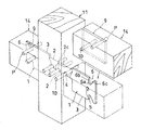
この第3実施例の接合具1は、例えば図6に示すように、柱11に梁14を架け渡す際において、柱11と梁14との接合などに利用することができる。柱11も梁14も断面矩形の角材からなる。柱11は、上下方向に立設されており、その一側面に、水平に配置された梁14の長手方向の端部を接合することになる。
【0029】
接合に際しては、柱11に形成した穴に、棒状の取付部2を差し込んで、それとは垂直方向に差し込まれるピンにて、接合具1は柱11に固定される。これにより、板状の接合部3は、柱11の一側面から垂直に突出し、且つ柱11の長手方向(上下方向)に沿って配置される。また、本実施例では、接合部3が、柱11の一側面の幅方向中央部に配置される。
【0030】
一方、梁14の長手方向の端部には、細長いスリット状の差込溝9を形成しておく。図示例では、梁14の幅方向中央部に、梁14の長手方向に沿って差込溝9が形成されている。この差込溝9の幅寸法は、接合部3の板厚よりも若干大きく形成されている。また、梁14には、接合部3に梁14を取り付けた状態で、上方の切欠き6の底部6aに対応する位置に、差込溝9を横切って予めピン(引寄せピン)Pを設けておく。
【0031】
柱11に梁14を接合するには、柱11の側面から垂直に突出する接合部3に、梁14の差込溝9を差し込んで、接合部3の切欠き6に前記引寄せピンPを落とし込めばよい。切欠き6の傾斜面6cの作用により、引寄せピンPは自動的に切欠き6の底部6aへ配置される。そして、その状態では、梁14の端面が柱11の側面にほぼ当接した状態とされる。その状態で、梁14には、接合部3の板面中央に形成された貫通穴5と対応する位置に、予めピン穴10が形成されているので、そのピン穴10と前記貫通穴5にピンを差し込めばよい。
【0032】
ところで、本実施例の取付部2は、先端側が略半円形状断面に切り欠かれていることを利用して、図6に示すように、柱11の向かい合った側面に、それぞれ接合具1,1を介して梁14,14を接合するのが容易である。つまり、柱11の左右両側面に貫通して穴を形成し、その左右に接合具1の取付部2を差し込めばよい。その際、二つの接合具1は、互いに左右反転された状態であるから、各取付部2の先端部2c同士が重ね合わされることになる。
【0033】
これにより、二つの取付部2が、連続的に一本の棒状になる。そして、その取付部2に形成された穴4を通すように、柱11の前後方向に沿って3つのピンを差し込めばよい。これにより、柱11の左右側面に、それぞれ板状の接合部3が配置された状態となるので、その接合部3にそれぞれ梁14を接合すればよい。
【0034】
図7は、本発明の軸組接合具1の第4実施例を示す斜視図である。
この実施例の接合具1は、第3実施例(図5)の接合具1の変形例である。この実施例の場合、前記第3実施例の接合具1に、棒状の取付部2をもう一本増やして、取付部2を2本とした例を示している。図7において上方の取付部2は、前記第3実施例のものと同様の構成である。下側の取付部2は、上側の取付部2と平行に配置され、上側の取付部2よりも短く、図示例の場合約半分程度の長さとされている。そして、この下側の取付部2にも、接合部3の板面に垂直方向の貫通穴4が形成されている。
【0035】
この第4実施例の接合具1も、前記第3実施例と同様にして使用することができる。ただ、取付部2が2本形成されているので、それに伴って、柱11の側面には上下に二つの穴をあけることになる。上側の穴は、前述したように貫通穴であるが、下側の穴は、貫通穴でもよいし、そうでなくともよい。そして、上下の穴に、上下の取付部2を差し込んだ後、それぞれの取付部2に形成した貫通穴4を介して、柱11の前後方向にピンを差し込めばよい。
【0036】
図8は、本発明の軸組接合具1の第5実施例を示す斜視図であり、図9は、その接合具1の使用状態を示す斜視図である。
この実施例の接合具1は、前記第4実施例の接合具1の変形例である。この実施例の場合、板状の接合部3がやや大きく形成されている。そして、それに伴い、接合部3には、使用時にピンが通される貫通穴5の数を増やしている。図示例では、貫通穴5を3つ形成した例を示している。
【0037】
本実施例の場合、接合具1を上下反転しても使用可能に、接合部3には上下対称位置に切欠き6や貫通穴5が形成されている。つまり、上下両端部に略レ字形状の切欠き6が形成され、各切欠き6よりもやや上下方向内側に貫通穴5が形成され、さらに接合部3の上下方向中央部に貫通穴5が形成されている。
【0038】
本実施例の接合具1は、例えば図9に示すように、柱11と梁14との接合などに使用することができる。この接合具1を介しての柱11と梁14との接合方法は、前記第4実施例と同様であるが、梁14に予め固定した引寄せピンPの他、接合部3の下側二箇所の穴5,5にそれぞれ梁14を介してピンを差し込んで取り付ける。
【0039】
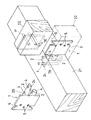
図10は、本発明の軸組接合具1の第6実施例の使用状態を示す斜視図である。
この実施例の接合具1は、前記第5実施例の接合具1の変形例である。この実施例の場合、取付部2に形成する切欠きと貫通穴4の形成位置・形成方向が異なる。つまり、本実施例の接合具1では、上下二本の取付部2,2の内、上側の取付部2の先端側2cが、丸棒の上下方向半分を水平に切除された形状とされている。そして、その取付部2には、先端側2cと基端側2bに、それぞれ上下方向に貫通穴4,4が形成されている。そして、下側の取付部2には、上側の取付部2の基端側2bに形成された穴と同軸上に、貫通穴4が上下方向に形成されている。
【0040】
この実施例の接合具1は、梁又は土台からなる第1部材21と、梁又は大引からなる第2部材22との接合に使用される。第1部材21の側面には、接合具1の取付部2を差し込む穴を水平方向に形成しておき、その穴に取付部2を差し込んだ後、取付部2の先端側2cと基端側2bにそれぞれピンを上下方向に差し込んで固定すればよい。基端側のピンは、上下二つの取付部2,2の各貫通穴4,4に通されることになる。なお、この実施例の場合、上側の取付部2に形成する切欠きの位置を、上下反転させた別の接合具1を用意すれば、図6や図9の場合と同様にして、第1部材21の対向面に接合具1,1を取り付けて、二つの第2部材22,22を接合することができる。
【0041】
以上の各実施例に述べたように、軸組接合具1は、少なくとも一方の部材への取付部2が丸棒状とされている。そして、その製造は、熱間鍛造や鋳造により行われる。また、その取付けは、取り付けようとする部材に、ドリルなどで穴を開けて、取付部2を差し込んだ後、前記穴と直角方向に形成しておいたピン穴にピンを差し込んで、そのピンを取付部2に形成しておいた貫通穴4に通すことで行われる。
【0042】
このように、ボルトナットによらずに、ピンの差し込みだけでも取り付けが可能である。よって、施工が極めて容易である。また、ボルトの頭や軸先端、或いはナットが、柱などの表面から突出しないので、梁などにそれらを収容するための溝や穴を特別に形成する必要もない。さらに、取付部2は、柱などの表面に単に沿わせるだけでなく、柱などの部材中に差し込む構成である。従って、きわめて強固に取り付けることができる。
【0043】
ところで、取付部2は、丸棒状であるから、取付時にピンが通される貫通穴4の形成方向を適宜に設定できる。例えば、各実施例では、取付部2には、前後方向(接合部3の板面と垂直方向)に貫通穴4を開けているが、上下方向に貫通穴4を開けてもよい。
【0044】
なお、本発明の建築用軸組接合具1は、上記実施例の構成に限らず適宜変更可能である。
特に、取付部2や接合部3の形状や大きさ、貫通穴4,5の形成位置や形成個数、取付部2の数は適宜に変更可能である。また、上記各実施例の接合具1の適用箇所は一例であって、それ以外の部分にも適用可能である。例えば、第5実施例(図8)の接合具1は、柱と梁の接合だけでなく、胴差と梁との接合にも使用可能である。
【0045】
【発明の効果】
以上詳述したように、本発明の建築用軸組接合具によれば、製造、搬送及び取付施工が容易で、しかも強固な接合が可能である。
【図面の簡単な説明】
【図1】本発明の軸組接合具の第1実施例を示す斜視図である。
【図2】図1の接合具の使用状態を示す斜視図である。
【図3】本発明の軸組接合具の第2実施例を示す斜視図である。
【図4】図3の接合具の使用状態を示す斜視図である。
【図5】本発明の軸組接合具の第3実施例を示す斜視図である。
【図6】図5の接合具の使用状態を示す斜視図である。
【図7】本発明の軸組接合具の第4実施例を示す斜視図である。
【図8】本発明の軸組接合具の第5実施例を示す斜視図である。
【図9】図8の接合具の使用状態を示す斜視図である。
【図10】本発明の軸組接合具の第6実施例の使用状態を示す斜視図である。
【符号の説明】
1 建築用軸組接合具
2 取付部
3 接合部
4 貫通穴
5 貫通穴
6 切欠き
9 差込溝
10 ピン穴
11 柱
12 土台
13 管柱
14 梁
P ピン[0001]
BACKGROUND OF THE INVENTION
TECHNICAL FIELD The present invention relates to an architectural frame connector used for joining columns and beams or joining columns and foundations in a wooden frame construction method.
[0002]
[Prior art]
2. Description of the Related Art Conventionally, for example, when a beam is bridged over a column, it is known that the column and the beam are joined to each other via an architectural frame connector. In this conventional connector, the other plate-like piece is integrally provided on one side edge of one piece of the rectangular plate-like piece perpendicular to the one piece. In use, the beam is fixed to the one piece after the other piece is overlapped on the surface of the pillar and bolted so that the one piece projects vertically from the surface of the pillar.
[0003]
[Problems to be solved by the invention]
However, in the above conventional method, it takes time to fix the other piece of the joint to the column. In other words, in a state in which the other piece of the joint was superposed on the surface of the column, the bolt could be passed through the column, and then it could not be fixed unless the nut was tightened on the opposite side.
[0004]
And in the case of such an attachment method, not only the said other piece but the front-end | tip and nut of a volt | bolt will protrude from the surface of a pillar. In order to prevent gaps at the joint between the column and the beam after construction, a groove or notch in which the other piece or the bolt and nut that holds it to the column is stored is formed on the surface of the column or the end of the beam There was a need to form. Further, in the conventional configuration, when the connector is fixed with a single bolt, there is a possibility that the connector may rotate around the bolt, and there are some places where the bolt must be fixed with two bolts.
[0005]
For this reason, in the case of a conventional shaft assembly connector, it is difficult to respond on site, and it is necessary to attach the connector to one member (column in the above example) in advance at the factory. Therefore, it was bulky when transported from the factory to the construction shop / each site, and efficient transportation was not possible.
[0006]
The present invention has been made in view of the above circumstances, and a main object thereof is to provide an architectural frame connector that is easy to manufacture, transport, and attach and can be firmly attached.
[0007]
[Means for Solving the Problems]
In order to achieve the above object, the building frame joint tool of the present invention is a building frame joint tool used for joining the first and second members made of columns, beams, foundations, or the like. The attachment portion to the first member and the joining portion to the second member are integrally formed, and the attachment portion is a rod-like shape inserted into the hole formed in the first member and has a periphery of the tip portion. Half of the direction is formed by cutting out , the joint is formed in a plate shape that is inserted into the groove formed in the second member, and the mounting portion and the joint are disposed in the first member or the second member. In this state, through holes are formed through which the rods inserted into these members are passed, and the attachment parts of other connectors and their tips are overlapped with each other, and the rods are passed through the respective through holes. When it passes, the two second members can be joined at corresponding positions sandwiching the first member .
[0008]
In use, first, a hole for attaching a connector is made in the first member, but this hole may be made in advance in the factory, but it is also easy to make it in the field. And what is necessary is just to insert a rod-shaped attachment part in the hole. A pin hole is formed in the first member at a position corresponding to the through hole of the mounting portion in advance, and this pin hole is formed in a direction perpendicular to the axial direction of the mounting portion, for example. Then, when a pin is inserted into the hole, the pin is passed through the through hole of the mounting portion. Not only the attachment portion is inserted into the first member, but also the pin is inserted along the radial direction, so that the connector is attached very firmly without rotating. After fixing the attachment portion in this manner, the attachment portion may be attached to the second member.
[0009]
DETAILED DESCRIPTION OF THE INVENTION
Hereinafter, the building frame connector of the present invention will be described in more detail.
The joint tool of the present invention is used for joining members made of columns, beams, foundations, or the like. For example, it is used for joining a column and a beam, joining a body difference and a beam, joining a column and a base, joining a tube column and a base, joining a tube column and a beam, and the like.
[0010]
FIG. 1 is a perspective view showing a first embodiment of a shaft assembly connector of the present invention, and FIG. 2 is a perspective view showing a use state of the connector.
In the
[0011]
In this embodiment, the
[0012]
As described above, in the
[0013]
The
[0014]
A hole for inserting the
[0015]
Therefore, after inserting the mounting
[0016]
The
[0017]
Incidentally, one or more through
[0018]
Thereby, the
[0019]
FIG. 3 is a perspective view showing a second embodiment of the
The
[0020]
The
[0021]
In addition, the formation position of the
[0022]
For example, as shown in FIG. 4, the
[0023]
For this purpose, a round hole into which the rod-shaped
[0024]
A
[0025]
An
[0026]
FIG. 5 is a perspective view showing a third embodiment of the
The
[0027]
On the other hand, a through-
[0028]
For example, as shown in FIG. 6, the
[0029]
At the time of joining, the rod-shaped
[0030]
On the other hand, an elongated slit-
[0031]
In order to join the
[0032]
By the way, the
[0033]
Thereby, the two
[0034]
FIG. 7 is a perspective view showing a fourth embodiment of the
The
[0035]
The
[0036]
FIG. 8 is a perspective view showing a fifth embodiment of the
The
[0037]
In the case of the present embodiment, a
[0038]
For example, as shown in FIG. 9, the
[0039]
FIG. 10 is a perspective view showing a usage state of the sixth embodiment of the
The
[0040]
The joining
[0041]
As described in each of the above embodiments, in the
[0042]
In this way, it is possible to attach by simply inserting a pin without using bolts and nuts. Therefore, construction is extremely easy. Further, since the bolt head, the shaft tip, or the nut does not protrude from the surface of the column or the like, it is not necessary to specially form a groove or a hole for accommodating them in the beam or the like. Furthermore, the
[0043]
By the way, since the
[0044]
In addition, the
In particular, the shape and size of the
[0045]
【The invention's effect】
As described above in detail, according to the building frame connector of the present invention, manufacture, transportation, and installation are easy, and strong bonding is possible.
[Brief description of the drawings]
FIG. 1 is a perspective view showing a first embodiment of a shaft assembly connector of the present invention.
FIG. 2 is a perspective view showing a usage state of the connector of FIG. 1;
FIG. 3 is a perspective view showing a second embodiment of the shaft assembly connector of the present invention.
4 is a perspective view showing a usage state of the connector of FIG. 3. FIG.
FIG. 5 is a perspective view showing a third embodiment of the shaft connector of the present invention.
6 is a perspective view showing a usage state of the connector of FIG. 5. FIG.
FIG. 7 is a perspective view showing a fourth embodiment of the shaft connector of the present invention.
FIG. 8 is a perspective view showing a fifth embodiment of the shaft connector of the present invention.
9 is a perspective view showing a usage state of the connector of FIG. 8. FIG.
FIG. 10 is a perspective view showing a usage state of a sixth embodiment of the shaft connector of the present invention.
[Explanation of symbols]
DESCRIPTION OF
Claims (3)
第1部材への取付部と、第2部材への接合部とを備えて一体形成され、
取付部は、第1部材に形成された穴に差し込まれる棒状であって、先端部の周方向半分が切り欠かれて形成され、
接合部は、第2部材に形成された溝に差し込まれる板状に形成され、
取付部及び接合部には、第1部材又は第2部材内に配置された状態で、それら部材に差し込まれる棒材が通される貫通穴が形成され、他の接合具の取付部と、その先端部同士を重ね合わせ、互いの貫通穴に貫通して棒材を通すと、第1部材を挟んだ対応位置に2つの第2部材が接合可能とされることを特徴とする建築用軸組接合具。A building frame joint used for joining the first and second members made of columns, beams or foundations,
It is integrally formed with an attachment part to the first member and a joint part to the second member,
The attachment portion is a rod shape that is inserted into a hole formed in the first member, and is formed by cutting away the circumferential half of the tip portion .
The joint is formed in a plate shape that is inserted into the groove formed in the second member ,
In the state of being arranged in the first member or the second member in the attachment part and the joint part, a through hole through which a bar inserted into these members passes is formed, and the attachment part of the other joint tool, The construction shaft characterized in that two second members can be joined at corresponding positions sandwiching the first member when the tip portions are overlapped and passed through the through holes and passed through the bar. Pair connector.
Priority Applications (1)
| Application Number | Priority Date | Filing Date | Title |
|---|---|---|---|
| JP2002149760A JP3668207B2 (en) | 2002-05-23 | 2002-05-23 | Architectural frame connector |
Applications Claiming Priority (1)
| Application Number | Priority Date | Filing Date | Title |
|---|---|---|---|
| JP2002149760A JP3668207B2 (en) | 2002-05-23 | 2002-05-23 | Architectural frame connector |
Publications (2)
| Publication Number | Publication Date |
|---|---|
| JP2003336321A JP2003336321A (en) | 2003-11-28 |
| JP3668207B2 true JP3668207B2 (en) | 2005-07-06 |
Family
ID=29706415
Family Applications (1)
| Application Number | Title | Priority Date | Filing Date |
|---|---|---|---|
| JP2002149760A Expired - Fee Related JP3668207B2 (en) | 2002-05-23 | 2002-05-23 | Architectural frame connector |
Country Status (1)
| Country | Link |
|---|---|
| JP (1) | JP3668207B2 (en) |
Families Citing this family (3)
| Publication number | Priority date | Publication date | Assignee | Title |
|---|---|---|---|---|
| JP5451549B2 (en) * | 2010-07-13 | 2014-03-26 | 義邦 大倉 | Connecting bracket |
| JP7018207B2 (en) * | 2019-05-12 | 2022-02-10 | 株式会社ストローグ | Connection structure |
| BE1028755B1 (en) | 2020-10-29 | 2022-05-31 | Bewerk | BUILD CONNECTION |
-
2002
- 2002-05-23 JP JP2002149760A patent/JP3668207B2/en not_active Expired - Fee Related
Also Published As
| Publication number | Publication date |
|---|---|
| JP2003336321A (en) | 2003-11-28 |
Similar Documents
| Publication | Publication Date | Title |
|---|---|---|
| JP3668207B2 (en) | Architectural frame connector | |
| JP2010281192A (en) | Joint fitting, fixation fitting and fixing pin for building | |
| JP2005188722A (en) | Drift pin | |
| JP4350580B2 (en) | Wood lumber for construction | |
| JP4111214B2 (en) | How to mount the gate block reinforcing bar to the formwork for manufacturing the coupler assembling jig and the reinforcing bar with the coupler | |
| JP4277872B2 (en) | A method of joining a frame in a wooden building, a method of joining a frame using the same, and a method of joining column bases using a combination of common members. | |
| JPH11158997A (en) | Joint device for column and beam made of precast concrete and wall reinforcement of concrete wall | |
| JP5946271B2 (en) | Column base / column head joint set hardware and column base / column head joint structure | |
| JP3670984B2 (en) | Wooden building assembly structure and method for assembling the same | |
| JP7038446B1 (en) | Joint structure of wooden frame building | |
| JP2002129552A (en) | Spacer for cage | |
| JP2005213855A (en) | Mechanical reinforcement joint | |
| JPH0821011A (en) | Connector fittings for building | |
| JP2004232440A (en) | Steel structure connector | |
| JP3489825B2 (en) | A joining device having a pair of diaphragms for joining a reinforced concrete column and a horizontal steel beam | |
| JPH09151543A (en) | Joining member | |
| JP3475197B2 (en) | Joint structure of horizontal member and metal joint of horizontal member used for this structure | |
| JPH0960124A (en) | Joining/fixing method of two joined articles and joining/ fixture of two joined articles | |
| JPH085216Y2 (en) | PC steel rod coupling coupler | |
| JP3992646B2 (en) | Pillar joining equipment | |
| JP5065730B2 (en) | Member connector | |
| JP3383785B2 (en) | Joint equipment for building components | |
| JP3020190U (en) | Metal fittings for wooden members in wooden buildings | |
| JPH0715911U (en) | Reinforcing bar fittings | |
| JP2004225394A (en) | Jointing structure using rod-shaped joint element |
Legal Events
| Date | Code | Title | Description |
|---|---|---|---|
| A977 | Report on retrieval |
Free format text: JAPANESE INTERMEDIATE CODE: A971007 Effective date: 20040916 |
|
| A131 | Notification of reasons for refusal |
Free format text: JAPANESE INTERMEDIATE CODE: A131 Effective date: 20041005 |
|
| A521 | Written amendment |
Free format text: JAPANESE INTERMEDIATE CODE: A523 Effective date: 20041130 |
|
| TRDD | Decision of grant or rejection written | ||
| A01 | Written decision to grant a patent or to grant a registration (utility model) |
Free format text: JAPANESE INTERMEDIATE CODE: A01 Effective date: 20050308 |
|
| A61 | First payment of annual fees (during grant procedure) |
Free format text: JAPANESE INTERMEDIATE CODE: A61 Effective date: 20050407 |
|
| R150 | Certificate of patent or registration of utility model |
Free format text: JAPANESE INTERMEDIATE CODE: R150 |
|
| FPAY | Renewal fee payment (event date is renewal date of database) |
Free format text: PAYMENT UNTIL: 20090415 Year of fee payment: 4 |
|
| FPAY | Renewal fee payment (event date is renewal date of database) |
Free format text: PAYMENT UNTIL: 20100415 Year of fee payment: 5 |
|
| FPAY | Renewal fee payment (event date is renewal date of database) |
Free format text: PAYMENT UNTIL: 20110415 Year of fee payment: 6 |
|
| FPAY | Renewal fee payment (event date is renewal date of database) |
Free format text: PAYMENT UNTIL: 20110415 Year of fee payment: 6 |
|
| FPAY | Renewal fee payment (event date is renewal date of database) |
Free format text: PAYMENT UNTIL: 20120415 Year of fee payment: 7 |
|
| FPAY | Renewal fee payment (event date is renewal date of database) |
Free format text: PAYMENT UNTIL: 20130415 Year of fee payment: 8 |
|
| FPAY | Renewal fee payment (event date is renewal date of database) |
Free format text: PAYMENT UNTIL: 20140415 Year of fee payment: 9 |
|
| LAPS | Cancellation because of no payment of annual fees |