JP3667775B2 - Automatic transmission - Google Patents
Automatic transmission Download PDFInfo
- Publication number
- JP3667775B2 JP3667775B2 JP23469891A JP23469891A JP3667775B2 JP 3667775 B2 JP3667775 B2 JP 3667775B2 JP 23469891 A JP23469891 A JP 23469891A JP 23469891 A JP23469891 A JP 23469891A JP 3667775 B2 JP3667775 B2 JP 3667775B2
- Authority
- JP
- Japan
- Prior art keywords
- fastening mechanism
- piston
- hydraulic fastening
- hydraulic
- clutch
- Prior art date
- Legal status (The legal status is an assumption and is not a legal conclusion. Google has not performed a legal analysis and makes no representation as to the accuracy of the status listed.)
- Expired - Fee Related
Links
Images
Classifications
-
- F—MECHANICAL ENGINEERING; LIGHTING; HEATING; WEAPONS; BLASTING
- F16—ENGINEERING ELEMENTS AND UNITS; GENERAL MEASURES FOR PRODUCING AND MAINTAINING EFFECTIVE FUNCTIONING OF MACHINES OR INSTALLATIONS; THERMAL INSULATION IN GENERAL
- F16H—GEARING
- F16H57/00—General details of gearing
- F16H57/08—General details of gearing of gearings with members having orbital motion
-
- F—MECHANICAL ENGINEERING; LIGHTING; HEATING; WEAPONS; BLASTING
- F16—ENGINEERING ELEMENTS AND UNITS; GENERAL MEASURES FOR PRODUCING AND MAINTAINING EFFECTIVE FUNCTIONING OF MACHINES OR INSTALLATIONS; THERMAL INSULATION IN GENERAL
- F16H—GEARING
- F16H3/00—Toothed gearings for conveying rotary motion with variable gear ratio or for reversing rotary motion
- F16H3/44—Toothed gearings for conveying rotary motion with variable gear ratio or for reversing rotary motion using gears having orbital motion
- F16H3/62—Gearings having three or more central gears
- F16H3/66—Gearings having three or more central gears composed of a number of gear trains without drive passing from one train to another
- F16H3/663—Gearings having three or more central gears composed of a number of gear trains without drive passing from one train to another with conveying rotary motion between axially spaced orbital gears, e.g. a stepped orbital gear or Ravigneaux
-
- F—MECHANICAL ENGINEERING; LIGHTING; HEATING; WEAPONS; BLASTING
- F16—ENGINEERING ELEMENTS AND UNITS; GENERAL MEASURES FOR PRODUCING AND MAINTAINING EFFECTIVE FUNCTIONING OF MACHINES OR INSTALLATIONS; THERMAL INSULATION IN GENERAL
- F16H—GEARING
- F16H2200/00—Transmissions for multiple ratios
- F16H2200/003—Transmissions for multiple ratios characterised by the number of forward speeds
- F16H2200/0043—Transmissions for multiple ratios characterised by the number of forward speeds the gear ratios comprising four forward speeds
-
- F—MECHANICAL ENGINEERING; LIGHTING; HEATING; WEAPONS; BLASTING
- F16—ENGINEERING ELEMENTS AND UNITS; GENERAL MEASURES FOR PRODUCING AND MAINTAINING EFFECTIVE FUNCTIONING OF MACHINES OR INSTALLATIONS; THERMAL INSULATION IN GENERAL
- F16H—GEARING
- F16H2200/00—Transmissions for multiple ratios
- F16H2200/20—Transmissions using gears with orbital motion
- F16H2200/2002—Transmissions using gears with orbital motion characterised by the number of sets of orbital gears
- F16H2200/2005—Transmissions using gears with orbital motion characterised by the number of sets of orbital gears with one sets of orbital gears
-
- F—MECHANICAL ENGINEERING; LIGHTING; HEATING; WEAPONS; BLASTING
- F16—ENGINEERING ELEMENTS AND UNITS; GENERAL MEASURES FOR PRODUCING AND MAINTAINING EFFECTIVE FUNCTIONING OF MACHINES OR INSTALLATIONS; THERMAL INSULATION IN GENERAL
- F16H—GEARING
- F16H2200/00—Transmissions for multiple ratios
- F16H2200/20—Transmissions using gears with orbital motion
- F16H2200/202—Transmissions using gears with orbital motion characterised by the type of Ravigneaux set
- F16H2200/2023—Transmissions using gears with orbital motion characterised by the type of Ravigneaux set using a Ravigneaux set with 4 connections
-
- Y—GENERAL TAGGING OF NEW TECHNOLOGICAL DEVELOPMENTS; GENERAL TAGGING OF CROSS-SECTIONAL TECHNOLOGIES SPANNING OVER SEVERAL SECTIONS OF THE IPC; TECHNICAL SUBJECTS COVERED BY FORMER USPC CROSS-REFERENCE ART COLLECTIONS [XRACs] AND DIGESTS
- Y10—TECHNICAL SUBJECTS COVERED BY FORMER USPC
- Y10T—TECHNICAL SUBJECTS COVERED BY FORMER US CLASSIFICATION
- Y10T74/00—Machine element or mechanism
- Y10T74/21—Elements
- Y10T74/2186—Gear casings
Landscapes
- Engineering & Computer Science (AREA)
- General Engineering & Computer Science (AREA)
- Mechanical Engineering (AREA)
- Gear-Shifting Mechanisms (AREA)
- Structure Of Transmissions (AREA)
Description
【0001】
【産業上の利用分野】
本発明は、自動変速装置に関し、特に、油圧締結機構の配置に関する。
【0002】
【従来の技術】
従来、車両の進行方向を横切って配置され、軸方向寸法の短縮化が求められる、いわゆるFF型の自動変速装置の端部に油圧締結機構を配置した構造として、例えば、多板ブレーキを構成するクラッチプレート類,ピストン,リターンスプリングをトランスミッションケースの端部に収納したものや、トランスミッションケースの開口端部を塞ぐサイドカバー内に収納したものがある。
【0003】
前者の場合、例えば、TOYOTA A240E オートマチックトランスアクスル修理書第3−4頁(1987年5月26日トヨタ自動車株式会社発行)に記載されたものが知られていて、トランスミッションケースの端部にピストンおよびリターンスプリングを収容するシリンダ室が形成され、このシリンダ室よりもケース中央側に多板クラッチのクラッチプレート類が収容された構造が示されている。
【0004】
後者の場合、TOYOTA A140系,A141系 オートマチックトランスアクスル修理書第3−7,3−8頁(1985年5月24日トヨタ自動車株式会社発行)や三菱オートマチックトランスミッション AUTOMATIC TRANSMISSION KM170,KM171,KM172,KM175 整備解説書第5頁(1983年10月三菱自動車工業株式会社発行)に記載されたものリングを収容するシリンダ室が形成され、このサイドカバーの他端側に縦壁が形成され、この縦壁と前記シリンダ室との間にクラッチプレート類が収容された構造が示されている。
【0005】
【発明が解決しようとする課題】
しかしながら、上述の従来の自動変速装置によれば、油圧締結機構を収容する空間を形成するにあたり、トランスミッションケース側に形成する前者の従来技術では、トランスミッションケースの端部にシリンダ室を形成するための縦壁を立てる必要があり、また、サイドカバー側に形成する後者の従来技術では、サイドカバーのトランスミッションケース側端部に、縦壁を立てる必要があり、これらの壁の分だけ装置の軸方向寸法が増加してしまうという問題があった。
【0006】
さらに、いずれの従来技術であっても、締結機構を組み付けた後に、サイドカバーをトランスミッションケースに取り付けるというように、2行程必要であって、作業性の向上が望まれていた。なお、特公昭47−29221号公報に作業性を向上できる自動変速装置が記載されているが、これは比較的軸方向寸法の自由度が高いFR型の自動変速装置である。
【0007】
本発明は上記のような問題に着目してなされたもので、油圧締結機構を収容するための縦壁を減らして自動変速装置の軸方向寸法の短縮化を図ると共に、作業性を向上させることができる自動変速装置を提供することを目的としている。
【0008】
【課題を解決するための手段】
そこで本発明は、トランスミッションケース側にプレートを収納し、サイドカバーにピストンを収容するシリンダ室を形成して縦壁を無くし、上述の問題を解決することとした。
【0009】
すなわち、請求項1記載の自動変速機にあっては、一端側にトルクコンバータが配置されると共に、変速装置を内部に収容するトランスミッションケースおよび、このトランスミッションケースの他端側にボルトにより締結されてトランスミッションケースの他端開口を塞ぐサイドカバーが設けられ、
前記サイドカバーと前記トルクコンバータとの間から動力を出力する出力ギヤが設けられ、
前記トランスミッションケースの前記サイドカバー側端部に、第1の油圧締結機構が設けられ、
この第1の油圧締結機構は、トランスミッションケース側に結合されたプレートおよびトランスミッションケース内の回転体に結合されたプレートと、油圧により作動して両プレートを締結させるピストンとを有し、
前記ピストンを摺動可能に収容するシリンダ室が、サイドカバーの端面に形成されており、
前記サイドカバーは、前記第1の油圧締結機構のシリンダ室の径方向内側に凹陥部を有し、
前記変速装置は、第1の油圧締結機構以外に第2の油圧締結機構を有し、
前記第2の油圧締結機構は、少なくとも一部が前記サイドカバーの凹陥部内に延びるクラッチドラムと、該クラッチドラム内に摺動可能に収容されたクラッチピストンとを有し、
前記第2の油圧締結機構のクラッチドラムの外周部は、前記サイドカバー凹陥部内に延びる小径部と、前記クラッチプレートが配置された大径部とを有する段付き形状をしており、
前記第1の油圧締結機構のプレートに対し、前記第2の油圧機構のクラッチプレートが前記ピストン側方向にオフセットされて該ピストンとの間に配置され、
前記第2の油圧締結機構のクラッチドラム大径部の径方向外側には、前記第1の油圧締結機構のプレートを押圧する前記ピストンの腕及び前記ピストンに設けられるリターンスプリングが配置されており、
前記第2の油圧締結機構のクラッチドラム大径部の一部が、前記第1の油圧締結機構のピストンの一部と半径方向にオーバーラップして配置され、
前記第1の油圧締結機構が、前記トランスミッションケース内の回転体に形成されて、前記プレート内周部とスプライン結合する筒状のハブを有し、
前記第2の油圧締結機構のクラッチドラム大径部の一部が、前記ハブの前記ピストン側端部と半径方向にオーバーラップして配置されている構成とした。
請求項2記載の発明にあっては、請求項1記載の自動変速装置において、
前記ピストンの一部と半径方向にオーバーラップする前記クラッチドラム大径部が、回転数検出用部材である構成とした。
【0010】
【作用】
組付時は、一方のプレートをトランスミッションケース側に結合すると共に、他方のプレートを回転体側に結合する。そして、サイドカバーのシリンダ室にピストンを収容した上で、このサイドカバーをトランスミッションケースに取り付け固定する。これにより、第1の締結機構が組み上る。
【0011】
【実施例】
以下、本発明実施例を図面に基づいて説明する。
まず、実施例の構成について説明する。
【0012】
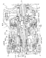
図2は、本発明実施例の自動変速装置を示す断面図であって、TCはトルクコンバータ,1はトランスミッションケース,2はサイドカバーである。すなわち、トランスミッションケース1は、内部に変速機構を収容し、その一端部がボルト3で固定されたサイドカバー2で塞がれている。
【0013】
そして、この自動変速装置は、動力が伝達されるインプットシャフトINおよびアウトプットギヤOUT と、このインプットシャフトIN−アウトプットギヤOUT の間に接続される前側遊星歯車FPG ,後側遊星歯車RPG と、4速の前進ギヤ比と1速の後退ギヤ比を達成すると共に、エンジンブレーキを制御したり、変速品質を高めるのに必要な締結要素としてのリバースクラッチREV/C ,バンドブレーキB/B ,ロークラッチLOW/C ,ロー&リバースブレーキL&R/B (第1の油圧締結機構),ハイクラッチH/C (第2の油圧締結機構),ローワンウェイクラッチLOW O.W.C と、インプットシャフトINおよびアウトプットギヤOUT (出力ギヤ)に連結される第1回転メンバM1,第2回転メンバM2,第3回転メンバM3とを備えている。
【0014】
前記前側遊星歯車FPG と後側遊星歯車RPG とは、1つの複合遊星歯車を構成していて、すなわち、前記第3回転メンバM3にはショートピニオンSPとロングピニオンLPとが回転自在に支持されており、前側遊星歯車FPG では、ロングピニオンLPが前側サンギヤSF と噛み合って動力を伝達していると共に、前側リングギヤRF と噛み合ってアウトプットギヤOUT に動力を伝達しており、後側遊星歯車RPG 側では、ショートピニオンSPが後側サンギヤSR と噛み合って動力を伝達している。
【0015】
前記第1回転メンバM1は、前側サンギヤSF と連結されている。
【0016】
前記第2回転メンバM2は、後側サンギヤSR に連結されている。
【0017】
前記リバースクラッチREV/C は、第1回転メンバM1とインプットシャフトINとを断接する。
【0018】
前記バンドブレーキB/B は、第1回転メンバM1とトランスミッションケース1とを断接する。
【0019】
前記ロークラッチLOW/C は、第2回転メンバM2とインプットシャフトINとを断接する。
【0020】
前記ロー&リバースブレーキL&R/B とローワンウェイクラッチLOW O.W.C は並設され、第3回転メンバM3とトランスミッションケース1とを断接する。
【0021】
前記ハイクラッチH/C は、第3回転メンバM3とインプットシャフトINとを断接する。
【0022】
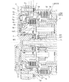
次に、実施例装置の要部を示す拡大断面図である図1により本発明を適用したロー&リバースブレーキL&R/B およびその周辺の構造について説明する。
【0023】
前記サイドカバー2の端面内側には、ハイクラッチ収容部2aとシリンダ室2bとが内外2重に形成されている。
【0024】
このハイクラッチ収容部2aには、前記ハイクラッチH/C の外周を構成するハイクラッチドラム4aのピストン4bを支持する部分が、相対回転可能に収容されている。
【0025】
前記ロー&リバースブレーキL&R/B は、クラッチプレート5a,5bとピストン5cとリターンスプリング5dとを備えている。両クラッチプレート5a,5bは、前記ハイクラッチH/C よりもトランスミッションケース1の中央側の位置において交互に配置され、一方のクラッチプレート5aは、トランスミッションケース1とスプライン結合されていると共に、他方のクラッチプレート5bは、第3回転メンバM3の一部を構成するハブ6にスプライン結合されている。また、両プレート5a,5bを油圧により押圧して締結させるピストン5cは、サイドカバー2に形成されたシリンダ室2bに軸方向に摺動自在に収容されている。そして、ピストン5cには、複数の腕5eが固着され、この腕5eにより前記プレート5a,5bを押圧するようになっている。また、この腕5eと腕5eの間には、ピストンを押し戻す前記リターンスプリング5dが配設されている。このリターンスプリング5dは、一端をピストン5cに取り付けると共に、他端をスプリングシート5fに取り付け、このスプリングシート5fのスプリング伸長方向への移動規制をトランスミッションケース1に取り付けたストッパ1aにより行っている。
【0026】
なお、前記シリンダ室2bには、ストッパ用穴2cが穿設され、このストッパ用穴2cにピストン5cに凸設した突起5gを差し込んで、ピストン5cの回転を規制している。
【0027】
また、図中7は、インプットシャフトINの回転数を検出するための回転数センサであって、トランスミッションケース1を貫通して設けられていると共に、さらに、前記ピストン5cの腕5eに形成されたセンサ用切欠5hを貫通して設けられ、先端が、前記インプットシャフトINにスプライン結合されているハイクラッチH/C のハイクラッチドラム4aに取り付けられたセンサ用板4cに近接されている。なお、このセンサ用板4cは、ハイクラッチドラム4aの外周に凹凸を形成するために取り付けられたもので、櫛の歯状に形成されている。
【0028】
次に、実施例の作用について説明する。
【0029】
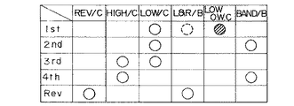
図3は、締結論理図を示している。
【0030】
第1速は、ロークラッチLOW/C を締結することで得られる。なお、この第1速では、加速時にはローワンウェイクラッチLOW O.W.C が締結作動し、エンジンブレーキ時にはロー&リバースブレーキL&R/B を締結させる。
【0031】
第2速は、ローワンウェイクラッチLOW/C とバンドブレーキB/B とを締結させることで得られる。
【0032】
第3速は、ハイクラッチH/C とロークラッチLOW/C とを締結させることで得られる。
【0033】
第4速は、ハイクラッチH/C とバンドブレーキB/B とを締結させることで得られる。
【0034】
後退速は、リバースクラッチREV/C とロー&リバースブレーキL&R/B とを締結させることで得られる。
【0035】
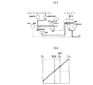
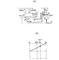
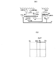
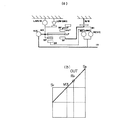
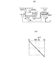
図4〜図8の(a)および(b)は、順に第1〜第4速,後退速のスケルトン図およびその共線図を示していて、図示のような動力伝達が成されて、図示のギヤ比が得られる。
【0036】
以上説明してきたように、実施例の自動変速装置にあっては、下記に列挙する特徴を有している。
【0037】
▲1▼ ロー&リバースブレーキL&R/B をハイクラッチH/C の外側に配設するにあたり、ハイクラッチドラム4aを支持するハイクラッチ収納部2aの外側にシリンダ室2bを形成してこのシリンダ室2bにピストン5cを収容し、一方、プレート5a,5bはハイクラッチH/C よりもトランスミッションケース1の中央側に配置して、ピストン5cにプレート5a,5bを押圧する腕5eを設けた構成としたため、シリンダ室2bの壁の部分をサイドカバー2の端面で兼用することとなって、サイドカバー2やトランスミッションケース1にシリンダ室2bを形成する縦壁がなくなり、その分だけ自動変速装置の軸方向寸法を短縮することができる。
【0038】
加えて、ピストン5cをハイクラッチH/C の一部と軸方向に重ねて配置させているため、このピストン5cをハイクラッチH/C の外周に配置するのに比べて、径方向寸法が小さくなって、装置のコンパクト化を図ることができる。
【0039】
▲2▼ 組付の際には、プレート5a,5bをトランスミッションケース1とハブ6とに交互に結合させ、一方、ピストン5cをシリンダ室2bの内部に収容し、さらに、このピストン5cにリターンスプリング5dおよびスプリングシート5fにセットした状態で、サイドカバー2をトランスミッションケース1に取り付けボルト3で固定すると、ロー&リバースブレーキL&R/B も組み付けを完了することになる。よって、組付作業性が良い。
【0040】
▲3▼ インプットシャフトIN(ハイクラッチドラム4a)の回転数を検出する回転センサ7を設けるにあたり、その外周に設けられているロー&リバースブレーキL&R/B のピストン5cとの位置をずらすことなく、ピストン5cにセンサ用切欠5hを形成して回転センサ7を貫通させて設けたために、軸方向寸法を短くできる。ちなみに、ピストン5cの位置をずらした場合には、シリンダ室2bを形成する縦壁が必要になって、この縦壁の分も軸方向寸法が長くなってしまう。
【0041】
以上、本発明の実施例を図面により説明してきたが、具体的な構成はこの実施例に限られるものではなく、本発明の要旨を逸脱しない範囲の設計変更等があっても本発明に含まれる。
【0042】
【発明の効果】
以上説明してきたように、請求項1記載の自動変速装置にあっては、トランスミッションケースの他端側にボルトにより締結されてトランスミッションケースの他端開口を塞ぐサイドカバーを設け、ピストンをサイドカバーに形成したシリンダ室を形成する縦壁を無くして、軸方向寸法を短縮して自動変速装置をコンパクトに形成することができるという効果が得られると共に、サイドカバーのトランスミッションケースへの取り付けと、第1の油圧締結機構の組付けとが同時に成されるため、作業性が向上するという効果が得られる。
また、サイドカバーは第1の油圧締結機構のシリンダ室の径方向内側に凹陥部を有し、変速装置は、第1の油圧締結機構以外に第2の油圧締結機構を有し、第2の油圧締結機構は、少なくとも一部がサイドカバーの凹陥部内に延びるクラッチドラムと、該クラッチドラム内に摺動可能に収容されたクラッチピストンとを有する構成としたため、2つの油圧締結機構を有しながら、サイドカバーの凹陥部内にクラッチドラムの一部を収容することで軸方向寸法を短縮することができる。
また、第2の油圧締結機構のクラッチドラムの外周部は、サイドカバーの凹陥部内に延びる小径部と、前記クラッチプレートが配置された大径部とを有する段付き形状をしている構成としたため、軸方向寸法と共に径方向寸法も短縮できる。
また、第1の油圧締結機構のプレートと第2の油圧締結機構のクラッチプレートとが軸方向にオフセット配置され、第2の油圧締結機構のクラッチドラムの径方向外側には、第1の油圧締結機構のプレートを押圧する前記ピストンの腕が配置されている構成としたため、空いているスペースを有効に使うことが可能になり、軸方向寸法と径方向寸法を短縮できる。
また、第1の油圧締結機構が、前記トランスミッションケース内の回転体に形成され、前記プレート内周部とスプライン結合する筒状のハブを有し、第2の油圧締結機構のクラッチドラム大径部の一部と前記ハブの前記ピストン側端部とが、半径方向にオーバーラップして配置されたことで、空いているスペースを有効に使うことが可能になり、軸方向寸法と径方向寸法を短縮できる。
請求項2記載の自動変速装置にあっては、前記ピストンの一部と半径方向にオーバーラップする前記クラッチドラム大径部を、回転数検出用部材としたことにより、前記ピストンと第1の油圧締結機構との間のスペースに効率良く回転数検出用部材をレイアウトすることが可能となり、回転数検出構造を含めた装置全体をコンパクトに構成することができる。
【図面の簡単な説明】
【図1】本発明実施例の自動変速装置の要部を示す拡大断面図である。
【図2】実施例装置を示す拡大断面図である。
【図3】実施例装置の締結論理図である。
【図4】本発明実施例装置の第1速を示すスケルトン図(a)およびその共線図(b)である。
【図5】本発明実施例装置の第2速を示すスケルトン図(a)およびその共線図(b)である。
【図6】本発明実施例装置の第3速を示すスケルトン図(a)およびその共線図(b)である。
【図7】本発明実施例装置の第4速を示すスケルトン図(a)およびその共線図(b)である。
【図8】本発明実施例装置の後退速を示すスケルトン図(a)およびその共線図(b)である。
【符号の説明】
1 トランスミッションケース
2 サイドカバー
2b シリンダ室
5a クラッチプレート
5c ピストン
6 ハブ(回転体)
L&R/B ロー&リバースブレーキ(油圧締結機構)[0001]
[Industrial application fields]
The present invention relates to an automatic transmission, and more particularly, to an arrangement of a hydraulic fastening mechanism.
[0002]
[Prior art]
Conventionally, as a structure in which a hydraulic fastening mechanism is arranged at an end portion of a so-called FF type automatic transmission that is arranged across a traveling direction of a vehicle and requires a reduction in axial dimension , for example, a multi-plate brake is configured. There are clutch plates, pistons, and return springs that are housed in the end of the transmission case, and those that are housed in side covers that close the open end of the transmission case.
[0003]
In the former case, for example, what is described in TOYOTA A240E Automatic Transaxle Repair Manual, pages 3-4 (issued by Toyota Motor Corporation on May 26, 1987) is known. A structure is shown in which a cylinder chamber for accommodating a return spring is formed, and clutch plates for a multi-plate clutch are accommodated closer to the center of the case than the cylinder chamber.
[0004]
In the latter case, TOYOTA A140 series, A141 series automatic transaxle repair manual pages 3-7, 3-8 (issued by Toyota Motor Corporation on May 24, 1985) and Mitsubishi automatic transmission AUTOMATIC TRANSMISSION KM170, KM171, KM172, KM175 The cylinder chamber that houses the ring is formed on the fifth page of the maintenance manual (issued by Mitsubishi Motors Corporation in October 1983), and the vertical wall is formed on the other end of the side cover. And a structure in which clutch plates are accommodated between the cylinder chamber and the cylinder chamber.
[0005]
[Problems to be solved by the invention]
However, according to the conventional automatic transmission described above, in forming the space for accommodating the hydraulic fastening mechanism, the former prior art formed on the transmission case side forms the cylinder chamber at the end of the transmission case. In the latter prior art formed on the side cover side, it is necessary to stand a vertical wall at the transmission case side end of the side cover, and the axial direction of the device is equivalent to these walls. There was a problem that the size would increase.
[0006]
Further, in any conventional technique, two steps are required, such as attaching the side cover to the transmission case after assembling the fastening mechanism, and improvement in workability has been desired. Japanese Patent Publication No. 47-29221 discloses an automatic transmission that can improve workability. This is an FR type automatic transmission that has a relatively high degree of freedom in axial dimensions.
[0007]
The present invention has been made paying attention to the above-mentioned problems, and reduces the vertical wall for housing the hydraulic fastening mechanism to shorten the axial dimension of the automatic transmission and improve the workability. An object of the present invention is to provide an automatic transmission that can perform the above.
[0008]
[Means for Solving the Problems]
Therefore, the present invention solves the above-mentioned problems by storing the plate on the transmission case side and forming a cylinder chamber for storing the piston in the side cover to eliminate the vertical wall.
[0009]
That is, in the automatic transmission according to the first aspect, the torque converter is disposed at one end side, the transmission case housing the transmission and the other end side of the transmission case are fastened by bolts. A side cover that closes the other end opening of the transmission case is provided,
An output gear that outputs power from between the side cover and the torque converter is provided,
A first hydraulic fastening mechanism is provided at the side cover side end of the transmission case,
The first hydraulic fastening mechanism has a plate coupled to the transmission case side, a plate coupled to a rotating body in the transmission case, and a piston that is actuated by hydraulic pressure to fasten both plates.
A cylinder chamber that slidably accommodates the piston is formed on an end surface of the side cover,
The side cover has a recessed portion on the radially inner side of the cylinder chamber of the first hydraulic fastening mechanism,
The transmission has a second hydraulic fastening mechanism in addition to the first hydraulic fastening mechanism,
The second hydraulic fastening mechanism has a clutch drum at least partially extending into the recessed portion of the side cover, and a clutch piston slidably accommodated in the clutch drum,
The outer peripheral part of the clutch drum of the second hydraulic fastening mechanism has a stepped shape having a small diameter part extending into the side cover recessed part and a large diameter part in which the clutch plate is disposed,
The clutch plate of the second hydraulic mechanism is offset in the piston side direction with respect to the plate of the first hydraulic fastening mechanism, and is disposed between the piston and the piston plate.
On the radially outer side of the large-diameter portion of the clutch drum of the second hydraulic fastening mechanism, an arm of the piston that presses the plate of the first hydraulic fastening mechanism and a return spring provided on the piston are arranged,
A portion of the clutch drum large-diameter portion of the second hydraulic fastening mechanism is disposed so as to overlap with a part of the piston of the first hydraulic fastening mechanism in the radial direction ,
Before SL first hydraulic engagement mechanism, wherein formed in the rotating body in the transmission case has a cylindrical hub splined said plate periphery,
A part of the large-diameter portion of the clutch drum of the second hydraulic fastening mechanism is disposed so as to overlap the end portion on the piston side of the hub in the radial direction.
In the second aspect of the invention, in the automatic transmission according to claim 1 Symbol placement,
The clutch drum large-diameter portion that overlaps a part of the piston in the radial direction is a rotation speed detection member.
[0010]
[Action]
At the time of assembly, one plate is coupled to the transmission case side, and the other plate is coupled to the rotating body side. And after accommodating a piston in the cylinder chamber of a side cover, this side cover is attached and fixed to a transmission case. Thereby, the first fastening mechanism is assembled.
[0011]
【Example】
Embodiments of the present invention will be described below with reference to the drawings.
First, the configuration of the embodiment will be described.
[0012]
FIG. 2 is a cross-sectional view showing an automatic transmission according to an embodiment of the present invention, where TC is a torque converter, 1 is a transmission case, and 2 is a side cover. That is, the transmission case 1 accommodates the speed change mechanism therein, and one end thereof is closed by the
[0013]
The automatic transmission includes an input shaft IN and an output gear OUT to which power is transmitted, a front planetary gear FPG and a rear planetary gear RPG connected between the input shaft IN and the output gear OUT. Reversing clutch REV / C, band brake B / B, low brake as low-speed gear ratios to achieve 4-speed forward gear ratio and 1-speed reverse gear ratio, as well as to control engine brake and improve gear shifting quality Clutch LOW / C, Low & Reverse Brake L & R / B (First Hydraulic Engagement Mechanism) , High Clutch H / C (Second Hydraulic Engagement Mechanism) , Low One-way Clutch LOW OWC, Input Shaft IN and Output Gear OUT A first rotating member M1, a second rotating member M2, and a third rotating member M3 connected to the (output gear) are provided.
[0014]
The front planetary gear FPG and the rear planetary gear RPG constitute one compound planetary gear, that is, a short pinion SP and a long pinion LP are rotatably supported by the third rotating member M3. cage, the front planetary gear FPG, with the long pinion LP is transmitting power in engagement with the front sun gear S F, which transmits power to the output gear oUT meshes with front ring gear R F, the rear planetary gear in RPG side is to transmit the power meshes with the short pinion SP is the rear sun gear S R.
[0015]
It said first rotary member M1 is coupled to the front sun gear S F.
[0016]
It said second rotary member M2 is connected to the rear sun gear S R.
[0017]
The reverse clutch REV / C connects and disconnects the first rotating member M1 and the input shaft IN.
[0018]
The band brake B / B connects and disconnects the first rotating member M1 and the transmission case 1.
[0019]
The low clutch LOW / C connects and disconnects the second rotating member M2 and the input shaft IN.
[0020]
The low & reverse brake L & R / B and the low one-way clutch LOW OWC are juxtaposed to connect and disconnect the third rotating member M3 and the transmission case 1.
[0021]
The high clutch H / C connects and disconnects the third rotating member M3 and the input shaft IN.
[0022]
Next, the low and reverse brake L & R / B to which the present invention is applied and the surrounding structure will be described with reference to FIG.
[0023]
On the inner side of the end surface of the
[0024]
In the high clutch housing portion 2a, a portion that supports the
[0025]
The low & reverse brake L & R / B includes
[0026]
The
[0027]
Reference numeral 7 in the figure denotes a rotational speed sensor for detecting the rotational speed of the input shaft IN. The rotational speed sensor is provided through the transmission case 1 and is formed on the
[0028]
Next, the operation of the embodiment will be described.
[0029]
FIG. 3 shows a fastening logic diagram.
[0030]
The first speed is obtained by engaging the low clutch LOW / C. In the first speed, the low one-way clutch LOW OWC is engaged during acceleration, and the low & reverse brake L & R / B is engaged during engine braking.
[0031]
The second speed is obtained by engaging the low one-way clutch LOW / C and the band brake B / B.
[0032]
The third speed is obtained by engaging the high clutch H / C and the low clutch LOW / C.
[0033]
The fourth speed can be obtained by engaging the high clutch H / C and the band brake B / B.
[0034]
The reverse speed is obtained by engaging the reverse clutch REV / C and the low & reverse brake L & R / B.
[0035]
FIGS. 4 to 8 (a) and (b) show a skeleton diagram and a collinear diagram of the first to fourth speeds and the reverse speed in order, and the power transmission as shown is made. The gear ratio can be obtained.
[0036]
As described above, the automatic transmission according to the embodiment has the characteristics listed below.
[0037]
(1) When the low & reverse brake L & R / B is disposed outside the high clutch H / C, a
[0038]
In addition, since the
[0039]
(2) When assembling, the
[0040]
(3) When the rotation sensor 7 for detecting the rotation speed of the input shaft IN (high clutch drum 4a) is provided, the position of the low & reverse brake L & R /
[0041]
The embodiment of the present invention has been described with reference to the drawings. However, the specific configuration is not limited to this embodiment, and design changes and the like within the scope of the present invention are included in the present invention. It is.
[0042]
【The invention's effect】
As described above, in the automatic transmission according to claim 1, the side cover that is fastened by the bolt to close the other end opening of the transmission case is provided on the other end side of the transmission case, and the piston is used as the side cover. The vertical wall that forms the formed cylinder chamber can be eliminated, the axial dimension can be shortened, and the automatic transmission can be compactly formed, and the side cover can be attached to the transmission case, Since the hydraulic fastening mechanism is assembled at the same time, the workability can be improved.
In addition, the side cover has a recessed portion radially inward of the cylinder chamber of the first hydraulic fastening mechanism, and the transmission has a second hydraulic fastening mechanism in addition to the first hydraulic fastening mechanism, Since the hydraulic fastening mechanism includes a clutch drum that extends at least partially in the recessed portion of the side cover and a clutch piston that is slidably accommodated in the clutch drum, the hydraulic fastening mechanism has two hydraulic fastening mechanisms. The axial dimension can be shortened by housing a part of the clutch drum in the recessed portion of the side cover.
Further, the outer peripheral portion of the clutch drum of the second hydraulic fastening mechanism has a stepped shape having a small diameter portion extending into the recessed portion of the side cover and a large diameter portion where the clutch plate is disposed. The radial dimension as well as the axial dimension can be shortened.
The plate of the first hydraulic fastening mechanism and the clutch plate of the second hydraulic fastening mechanism are offset in the axial direction, and the first hydraulic fastening is provided on the radially outer side of the clutch drum of the second hydraulic fastening mechanism. Since the piston arm that presses the plate of the mechanism is arranged, an empty space can be used effectively, and the axial dimension and the radial dimension can be shortened.
The first hydraulic engagement mechanism, wherein formed on the rotating member in the transmission case has a cylindrical hub splined the plate periphery, the clutch drum large diameter portion of the second hydraulic engagement mechanism Part of the hub and the piston-side end of the hub are arranged so as to overlap in the radial direction, so that a vacant space can be used effectively, and the axial dimension and the radial dimension can be reduced. Can be shortened.
The automatic transmission according to
[Brief description of the drawings]
FIG. 1 is an enlarged sectional view showing a main part of an automatic transmission apparatus according to an embodiment of the present invention.
FIG. 2 is an enlarged cross-sectional view showing an example device.
FIG. 3 is a fastening logic diagram of the embodiment device.
FIG. 4 is a skeleton diagram (a) and a collinear diagram (b) showing the first speed of the embodiment device of the present invention.
FIG. 5 is a skeleton diagram (a) and a collinear diagram (b) showing the second speed of the embodiment device of the present invention.
FIG. 6 is a skeleton diagram (a) and a collinear diagram (b) showing the third speed of the embodiment device of the present invention.
FIG. 7 is a skeleton diagram (a) and a collinear diagram (b) showing the fourth speed of the embodiment device of the present invention.
FIG. 8 is a skeleton diagram (a) and a collinear diagram (b) showing the reverse speed of the embodiment device of the present invention.
[Explanation of symbols]
1
L & R / B Low & reverse brake (hydraulic fastening mechanism)
Claims (2)
前記サイドカバーと前記トルクコンバータとの間から動力を出力する出力ギヤが設けられ、
前記トランスミッションケースの前記サイドカバー側端部に、第1の油圧締結機構が設けられ、
この第1の油圧締結機構は、トランスミッションケース側に結合されたプレートおよびトランスミッションケース内の回転体に結合されたプレートと、油圧により作動して両プレートを締結させるピストンとを有し、
前記ピストンを摺動可能に収容するシリンダ室が、サイドカバーの端面に形成されており、
前記サイドカバーは、前記第1の油圧締結機構のシリンダ室の径方向内側に凹陥部を有し、
前記変速装置は、第1の油圧締結機構以外に第2の油圧締結機構を有し、
前記第2の油圧締結機構は、少なくとも一部が前記サイドカバーの凹陥部内に延びるクラッチドラムと、該クラッチドラム内に摺動可能に収容されたクラッチピストンとを有し、
前記第2の油圧締結機構のクラッチドラムの外周部は、前記サイドカバー凹陥部内に延びる小径部と、前記クラッチプレートが配置された大径部とを有する段付き形状をしており、
前記第1の油圧締結機構のプレートに対し、前記第2の油圧機構のクラッチプレートが前記ピストン側方向にオフセットされて該ピストンとの間に配置され、
前記第2の油圧締結機構のクラッチドラム大径部の径方向外側には、前記第1の油圧締結機構のプレートを押圧する前記ピストンの腕及び前記ピストンに設けられるリターンスプリングが配置されており、
前記第2の油圧締結機構のクラッチドラム大径部の一部が、前記第1の油圧締結機構のピストンの一部と半径方向にオーバーラップして配置され、
前記第1の油圧締結機構が、前記トランスミッションケース内の回転体に形成されて、前記プレート内周部とスプライン結合する筒状のハブを有し、
前記第2の油圧締結機構のクラッチドラム大径部の一部が、前記ハブの前記ピストン側端部と半径方向にオーバーラップして配置されていることを特徴とする自動変速装置。 A torque converter is disposed on one end side, a transmission case that houses the transmission device, and a side cover that is fastened to the other end side of the transmission case by a bolt and closes the other end opening of the transmission case,
An output gear that outputs power from between the side cover and the torque converter is provided,
A first hydraulic fastening mechanism is provided at the side cover side end of the transmission case,
The first hydraulic fastening mechanism includes a plate coupled to the transmission case side and a plate coupled to a rotating body in the transmission case, and a piston that is actuated by hydraulic pressure to fasten both plates.
A cylinder chamber that slidably accommodates the piston is formed on an end surface of the side cover,
The side cover has a recessed portion on the radially inner side of the cylinder chamber of the first hydraulic fastening mechanism,
The transmission has a second hydraulic fastening mechanism in addition to the first hydraulic fastening mechanism,
The second hydraulic fastening mechanism has a clutch drum at least partially extending into the recessed portion of the side cover, and a clutch piston slidably accommodated in the clutch drum,
The outer peripheral part of the clutch drum of the second hydraulic fastening mechanism has a stepped shape having a small diameter part extending into the side cover recessed part and a large diameter part in which the clutch plate is disposed,
The clutch plate of the second hydraulic mechanism is offset in the piston side direction with respect to the plate of the first hydraulic fastening mechanism, and is disposed between the piston and the piston plate.
On the radially outer side of the large-diameter portion of the clutch drum of the second hydraulic fastening mechanism, an arm of the piston that presses the plate of the first hydraulic fastening mechanism and a return spring provided on the piston are arranged,
A portion of the clutch drum large-diameter portion of the second hydraulic fastening mechanism is disposed so as to overlap with a part of the piston of the first hydraulic fastening mechanism in the radial direction ,
The first hydraulic fastening mechanism has a cylindrical hub that is formed on a rotating body in the transmission case and is splined to the inner peripheral portion of the plate.
An automatic transmission according to claim 1, wherein a part of the large diameter portion of the clutch drum of the second hydraulic fastening mechanism is disposed so as to overlap the piston side end portion of the hub in the radial direction.
前記ピストンの一部と半径方向にオーバーラップする前記クラッチドラム大径部が、回転数検出用部材であることを特徴とする自動変速装置。The automatic transmission according to claim 1, wherein the clutch drum large-diameter portion that overlaps a part of the piston in the radial direction is a rotational speed detection member.
Priority Applications (3)
| Application Number | Priority Date | Filing Date | Title |
|---|---|---|---|
| JP23469891A JP3667775B2 (en) | 1991-09-13 | 1991-09-13 | Automatic transmission |
| DE4230462A DE4230462C2 (en) | 1991-09-13 | 1992-09-11 | Automatic transmission for motor vehicles |
| US08/307,094 US5495778A (en) | 1991-09-13 | 1994-09-16 | Automotive automatic transmission structure |
Applications Claiming Priority (1)
| Application Number | Priority Date | Filing Date | Title |
|---|---|---|---|
| JP23469891A JP3667775B2 (en) | 1991-09-13 | 1991-09-13 | Automatic transmission |
Publications (2)
| Publication Number | Publication Date |
|---|---|
| JPH05172247A JPH05172247A (en) | 1993-07-09 |
| JP3667775B2 true JP3667775B2 (en) | 2005-07-06 |
Family
ID=16975009
Family Applications (1)
| Application Number | Title | Priority Date | Filing Date |
|---|---|---|---|
| JP23469891A Expired - Fee Related JP3667775B2 (en) | 1991-09-13 | 1991-09-13 | Automatic transmission |
Country Status (3)
| Country | Link |
|---|---|
| US (1) | US5495778A (en) |
| JP (1) | JP3667775B2 (en) |
| DE (1) | DE4230462C2 (en) |
Families Citing this family (16)
| Publication number | Priority date | Publication date | Assignee | Title |
|---|---|---|---|---|
| JP3496238B2 (en) * | 1993-06-30 | 2004-02-09 | アイシン・エィ・ダブリュ株式会社 | Automatic transmission |
| EP0676562B1 (en) * | 1994-04-06 | 1998-06-24 | Hyundai Motor Company | Gear train of an automatic five-speed transmission for a vehicle |
| JP3369437B2 (en) * | 1997-04-30 | 2003-01-20 | ジヤトコ株式会社 | Support wall structure for toroidal type continuously variable automatic transmission |
| JP3807690B2 (en) * | 1997-05-13 | 2006-08-09 | 株式会社ハーモニック・ドライブ・システムズ | Rotation transmission mechanism using planetary gear mechanism |
| AT406986B (en) * | 1997-12-17 | 2000-11-27 | Steyr Daimler Puch Ag | REVERSIBLE REVERSE GEAR |
| GB2336634A (en) * | 1998-04-24 | 1999-10-27 | Delphi France Automotive Sys | Four-speed planetary gearing with ratio shift by operation of a single friction device |
| JP4096448B2 (en) * | 1998-06-05 | 2008-06-04 | アイシン・エィ・ダブリュ株式会社 | Automatic transmission |
| JP4051820B2 (en) * | 1998-09-01 | 2008-02-27 | アイシン・エィ・ダブリュ株式会社 | Automatic transmission for vehicles |
| JP4051814B2 (en) * | 1998-09-01 | 2008-02-27 | アイシン・エィ・ダブリュ株式会社 | Automatic transmission for vehicles |
| JP4144106B2 (en) * | 1998-12-21 | 2008-09-03 | アイシン・エィ・ダブリュ株式会社 | Automatic transmission for vehicles |
| DE19932613A1 (en) | 1999-07-13 | 2001-01-18 | Zahnradfabrik Friedrichshafen | Automatic transmission |
| SE515744C2 (en) * | 1999-12-13 | 2001-10-01 | Volvo Lastvagnar Ab | Hydraulically operated double clutch |
| US6364804B1 (en) * | 2000-08-28 | 2002-04-02 | General Motors Corporation | Multi-speed power transmission having six forward ratios and one reverse ratio |
| JP4715161B2 (en) * | 2004-10-26 | 2011-07-06 | アイシン・エィ・ダブリュ株式会社 | Planetary gear unit |
| JP4779341B2 (en) * | 2004-11-18 | 2011-09-28 | トヨタ自動車株式会社 | Piston for automatic transmission |
| US8986157B2 (en) * | 2008-03-14 | 2015-03-24 | Ford Global Technologies, Llc | Overrunning clutch reacting a force produced by a hydraulically actuated friction brake |
Family Cites Families (20)
| Publication number | Priority date | Publication date | Assignee | Title |
|---|---|---|---|---|
| US2862403A (en) * | 1954-01-25 | 1958-12-02 | Borg Warner | Transmission |
| US3053117A (en) * | 1959-06-22 | 1962-09-11 | Daimler Benz Ag | Planetary gear transmission |
| US3541887A (en) * | 1969-03-28 | 1970-11-24 | Gen Motors Corp | Transmission and control |
| US3613481A (en) * | 1969-11-24 | 1971-10-19 | Ford Motor Co | Reinforced case for an automatic transmission |
| JPS5219860A (en) * | 1975-08-08 | 1977-02-15 | Toyota Motor Corp | Driving device for automobile |
| JPS5834701B2 (en) * | 1975-12-02 | 1983-07-28 | トヨタ自動車株式会社 | Jido Hensoku Kiyou Gear Train |
| JPS6131765A (en) * | 1984-07-19 | 1986-02-14 | Aisin Warner Ltd | Four-wheel driving speed changer case |
| US4736653A (en) * | 1984-08-02 | 1988-04-12 | Aisin-Warner Limited | Power transmission |
| JPS6182070A (en) * | 1984-09-28 | 1986-04-25 | Aisin Warner Ltd | Four-wheel drive speed changer case |
| JPS61153061A (en) * | 1984-12-26 | 1986-07-11 | Aisin Warner Ltd | 4-wheel drive type transmission case |
| JPS61157873A (en) * | 1984-12-29 | 1986-07-17 | Aisin Warner Ltd | Vehicle transmission |
| WO1986006808A1 (en) * | 1985-05-04 | 1986-11-20 | Zahnradfabrik Friedrichshafen Ag | Gear-shifting box with planet wheels |
| EP0246511A3 (en) * | 1986-05-16 | 1988-10-19 | GETRAG Getriebe- und Zahnradfabrik GmbH | Planet gear transmission |
| JPH01312267A (en) * | 1988-06-10 | 1989-12-18 | Toyota Motor Corp | Automatic transmission for vehicle |
| JPH01153843A (en) * | 1987-12-11 | 1989-06-16 | Nissan Motor Co Ltd | Structure for supporting output shaft of automatic transaxle |
| US5188575A (en) * | 1988-04-29 | 1993-02-23 | Leising Maurice B | Automatic four-speed transmission with interconnected clutches |
| JPH02118258A (en) * | 1988-10-25 | 1990-05-02 | Nissan Motor Co Ltd | Joint portion of transmission case |
| JP2683396B2 (en) * | 1988-12-26 | 1997-11-26 | ジャトコ株式会社 | Automatic transmission with auxiliary transmission |
| DE3939651C1 (en) * | 1989-11-30 | 1991-05-08 | Mercedes-Benz Aktiengesellschaft, 7000 Stuttgart, De | |
| JP2911576B2 (en) * | 1990-09-28 | 1999-06-23 | ジャトコ株式会社 | Automatic transmission |
-
1991
- 1991-09-13 JP JP23469891A patent/JP3667775B2/en not_active Expired - Fee Related
-
1992
- 1992-09-11 DE DE4230462A patent/DE4230462C2/en not_active Expired - Fee Related
-
1994
- 1994-09-16 US US08/307,094 patent/US5495778A/en not_active Expired - Lifetime
Also Published As
| Publication number | Publication date |
|---|---|
| JPH05172247A (en) | 1993-07-09 |
| DE4230462A1 (en) | 1993-03-18 |
| DE4230462C2 (en) | 2000-04-27 |
| US5495778A (en) | 1996-03-05 |
Similar Documents
| Publication | Publication Date | Title |
|---|---|---|
| JP3667775B2 (en) | Automatic transmission | |
| JP3540481B2 (en) | Hydraulic engagement device for automatic transmission | |
| JP2988542B2 (en) | Automatic transmission | |
| JPH0723645Y2 (en) | Clutch device for automatic transmission with power take-off | |
| EP1783397B1 (en) | Automatic transmission for automotive vehicle | |
| JPH0932919A (en) | Friction engagement device for automatic transmission | |
| JP3301546B2 (en) | Automatic transmission | |
| US7582039B2 (en) | Automatic transmission for automotive vehicles | |
| JPH0617720B2 (en) | Hydraulic servo of friction engagement device of automatic transmission | |
| US4903548A (en) | Snap ring support device for an automatic transmission | |
| JP3450535B2 (en) | Automatic transmission friction engagement device | |
| JP3831334B2 (en) | Gear transmission for automatic transmission | |
| JP2004052804A (en) | Automatic transmission | |
| JPH08100844A (en) | Automatic transmission power transmission device | |
| KR0158170B1 (en) | The power train of automatic transmission for a vehicle | |
| JPH0416021Y2 (en) | ||
| JP2824262B2 (en) | Automatic transmission | |
| KR20020058737A (en) | Automatic transmission for vehicles | |
| JP4682876B2 (en) | Automatic transmission | |
| JPH0140739Y2 (en) | ||
| JPH11141662A (en) | Arrangement structure of automatic transmission brake piston | |
| JPH07269666A (en) | Automatic transmission | |
| JPS6120346Y2 (en) | ||
| JPS6218766Y2 (en) | ||
| JPH062066Y2 (en) | Gear train structure of automatic transmission |
Legal Events
| Date | Code | Title | Description |
|---|---|---|---|
| RD04 | Notification of resignation of power of attorney |
Free format text: JAPANESE INTERMEDIATE CODE: A7424 Effective date: 20041102 |
|
| A61 | First payment of annual fees (during grant procedure) |
Free format text: JAPANESE INTERMEDIATE CODE: A61 Effective date: 20050407 |
|
| R150 | Certificate of patent or registration of utility model |
Free format text: JAPANESE INTERMEDIATE CODE: R150 |
|
| FPAY | Renewal fee payment (event date is renewal date of database) |
Free format text: PAYMENT UNTIL: 20090415 Year of fee payment: 4 |
|
| FPAY | Renewal fee payment (event date is renewal date of database) |
Free format text: PAYMENT UNTIL: 20090415 Year of fee payment: 4 |
|
| FPAY | Renewal fee payment (event date is renewal date of database) |
Free format text: PAYMENT UNTIL: 20100415 Year of fee payment: 5 |
|
| FPAY | Renewal fee payment (event date is renewal date of database) |
Free format text: PAYMENT UNTIL: 20100415 Year of fee payment: 5 |
|
| FPAY | Renewal fee payment (event date is renewal date of database) |
Free format text: PAYMENT UNTIL: 20110415 Year of fee payment: 6 |
|
| LAPS | Cancellation because of no payment of annual fees |