JP3667553B2 - Inkjet printer head - Google Patents
Inkjet printer head Download PDFInfo
- Publication number
- JP3667553B2 JP3667553B2 JP9984099A JP9984099A JP3667553B2 JP 3667553 B2 JP3667553 B2 JP 3667553B2 JP 9984099 A JP9984099 A JP 9984099A JP 9984099 A JP9984099 A JP 9984099A JP 3667553 B2 JP3667553 B2 JP 3667553B2
- Authority
- JP
- Japan
- Prior art keywords
- piezoelectric element
- printer head
- thin film
- film transistor
- insulating substrate
- Prior art date
- Legal status (The legal status is an assumption and is not a legal conclusion. Google has not performed a legal analysis and makes no representation as to the accuracy of the status listed.)
- Expired - Lifetime
Links
- 239000010409 thin film Substances 0.000 claims description 72
- 239000000758 substrate Substances 0.000 claims description 60
- 239000000945 filler Substances 0.000 claims description 16
- 229910021420 polycrystalline silicon Inorganic materials 0.000 claims description 13
- 229910052751 metal Inorganic materials 0.000 claims description 10
- 239000002184 metal Substances 0.000 claims description 10
- 239000011159 matrix material Substances 0.000 claims description 4
- 125000006850 spacer group Chemical group 0.000 claims description 4
- 238000004519 manufacturing process Methods 0.000 description 20
- 238000000034 method Methods 0.000 description 16
- 230000008569 process Effects 0.000 description 11
- 238000010586 diagram Methods 0.000 description 10
- 230000004888 barrier function Effects 0.000 description 9
- 239000010408 film Substances 0.000 description 8
- 230000001681 protective effect Effects 0.000 description 8
- 239000000463 material Substances 0.000 description 7
- 238000005498 polishing Methods 0.000 description 6
- 229910052782 aluminium Inorganic materials 0.000 description 5
- XAGFODPZIPBFFR-UHFFFAOYSA-N aluminium Chemical compound [Al] XAGFODPZIPBFFR-UHFFFAOYSA-N 0.000 description 5
- 229910000679 solder Inorganic materials 0.000 description 5
- 239000000470 constituent Substances 0.000 description 4
- 230000004044 response Effects 0.000 description 4
- 230000015572 biosynthetic process Effects 0.000 description 3
- 230000020169 heat generation Effects 0.000 description 3
- BQCADISMDOOEFD-UHFFFAOYSA-N Silver Chemical compound [Ag] BQCADISMDOOEFD-UHFFFAOYSA-N 0.000 description 2
- 230000008859 change Effects 0.000 description 2
- 238000001816 cooling Methods 0.000 description 2
- 230000000694 effects Effects 0.000 description 2
- 238000004518 low pressure chemical vapour deposition Methods 0.000 description 2
- 229910052709 silver Inorganic materials 0.000 description 2
- 239000004332 silver Substances 0.000 description 2
- 238000004544 sputter deposition Methods 0.000 description 2
- 239000000919 ceramic Substances 0.000 description 1
- 229910021419 crystalline silicon Inorganic materials 0.000 description 1
- 230000006872 improvement Effects 0.000 description 1
- 238000009434 installation Methods 0.000 description 1
- HFGPZNIAWCZYJU-UHFFFAOYSA-N lead zirconate titanate Chemical compound [O-2].[O-2].[O-2].[O-2].[O-2].[Ti+4].[Zr+4].[Pb+2] HFGPZNIAWCZYJU-UHFFFAOYSA-N 0.000 description 1
- 229910052451 lead zirconate titanate Inorganic materials 0.000 description 1
- SWELZOZIOHGSPA-UHFFFAOYSA-N palladium silver Chemical compound [Pd].[Ag] SWELZOZIOHGSPA-UHFFFAOYSA-N 0.000 description 1
- 238000000926 separation method Methods 0.000 description 1
- 229910052710 silicon Inorganic materials 0.000 description 1
- 239000010703 silicon Substances 0.000 description 1
- 238000000638 solvent extraction Methods 0.000 description 1
- 238000005507 spraying Methods 0.000 description 1
Images


Landscapes
- Particle Formation And Scattering Control In Inkjet Printers (AREA)
Description
【0001】
【発明の属する技術分野】
本発明は、微小な液滴を紙面等の記録媒体に飛翔させて、文字や画像を記録するインクジェットプリンタヘッドの改良に関する。
【0002】
【従来の技術】
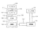
図11は圧電素子を用いてインク滴を吐出させる従来のインクジェットプリンタヘッドの構成の概略について一例を挙げて模式的に示す断面図、また、図12はインク滴の吐出動作に関わる機能の概略について示す機能ブロック図である。
【0003】
従来のインクジェットプリンタヘッド100は、図11に示されるように、ノズルを形成する小孔101を穿設した板状体102、および、その上に重合して固設された枠体状の圧力室構成部材103と、更に、圧力室構成部材103の上に重合して固設された振動板104によって構成される。圧力室構成部材103を形成する枠体の内側部分には所定の間隙を空けて複数の障壁105が設けられ、隣接する二つの障壁105と前述した板状体102および振動板104で区画して形成される各々の空間によって複数の圧力室106が構成される。
【0004】
また、圧力室構成部材103の内側には、全ての障壁105の先端部を突き切るようにしてインクプール107が形成され、振動板104のインクタンク口111を介して導入されたインクが、インクプール107、および、障壁105,105間の間隙で形成されるインク供給口112を通って各々の圧力室106に導かれるようになっている。
【0005】
圧電素子108は、各々の圧力室106と対応して振動板104上に複数配備され、また、ノズルを構成する小孔101も、各々の圧力室106と対応して板状体102上の複数箇所に穿設されている。
【0006】
図12に示されるように、インクタンク109内のインクは、チューブ110およびインクタンク口111を介してインクプール107に供給される。また、インクジェットプリンタヘッド100を駆動する駆動信号は、プリンタ本体113で生成され、フレキシブル・プリンティング・ケーブル(以下、単にFPCという)114を通って駆動回路用の回路基板115に到達し、更に、FPC116を通って圧電素子108に印加され、この信号を受けた圧電素子108が振動して圧力室106の振動板104を変形させる。この結果、圧力室106の容積が減少して圧力波が発生し、この圧力波により、ノズルとなる小孔101からインク滴が吐出されて紙面等に飛翔する。
【0007】
【発明が解決しようとする課題】
近年、インクジェットプリンタの分野においても印刷速度の高速化や高画質印刷という技術課題が問題となってきた。まず、高速化を実現するための手段としては、インクジェットプリンタヘッドのノズル数を増加することが挙げられる。また、高画質化を実現するためには、圧電素子に供給する電気信号を変化させて吐出されるインク滴の大きさを変え、紙面に付着するドットの大きさを変化させることが望まれる。この両者を満たすものとして高密度のインクジェットプリンタヘッドが必要となる。
【0008】
ところが、ノズルの数を増加させたり圧電素子に供給する電気信号を変化させる機能を持たせたりすると、必要とされる駆動回路の数も同様に冗長し、配線容量が増加する。例えば、図12に示されるように、圧電素子108が載った基板と駆動回路用の回路基板115とが異なる場合、FPC116等を介して接続を行うことになるが、FPC等の配線ピッチの高密度化にも限度があるので、インクジェットプリンタヘッド100に実装できるノズルや回路の数にも自ずと限界が生じ、必ずしも、高速化や高画質化に必要とされる十分な数のノズルや回路を実装できるとは限らない。
【0009】
また、FPCを用いず、相異なる基板、例えば、駆動回路用の回路基板115と圧電素子108が載った基板の夫々に接続用の端子を配備し、各々の端子を相互に接触させる手段も考えられるが、やはり端子間の配線ピッチの高密度化の限界に関する問題はついてまわる。
【0010】
プリンタ本体113から回路基板115に送る駆動用の信号に関しても同様の問題があり、ノズル数の増大に伴ってプリンタ本体113側のアンプ回路の数も増大するので、プリンタ本体113側に冷却用のヒートシンクフィン等の冷却装置が必要となり、小型インクジェットプリンタの実現が困難となる問題がある。
【0011】
【発明の目的】
そこで、本発明の目的は、配線や回路構成を高密度化し、印刷速度の高速化や高画質印刷に適したインクジェットプリンタヘッドを提供することにある。
【0012】
【課題を解決するための手段】
本発明は、インクを貯溜する圧力室にノズルと振動板を設け、電気信号で駆動される圧電素子によって前記振動板を振動させて前記ノズルからインク滴を吐出するように構成したインクジェットプリンタヘッドであって、複数のノズルがマトリクス状に配置されたノズルプレートと、前記複数のノズルに対応して圧力室を構成する圧力室構成部材と振動板とからなるプリントヘッド本体と、前記圧電素子に電気信号を供給するための薄膜トランジスタ回路を形成すると共に前記圧電素子を実装した絶縁基板とが、前記振動板を介し前記圧電素子上に前記圧力室が対応するよう前記ノズルにおけるインクの吐出方向に重合して一体に配備されていることを特徴とする構成により前記目的を達成した。
圧電素子に電気信号を供給するためのトランジスタ回路を薄膜トランジスタ回路によって形成することにより回路構成の高密度化が達成される。また、この薄膜トランジスタ回路を圧電素子と共に絶縁基板上に一体に配備することによってトランジスタ回路専用の基板が不要となり、同時に、圧電素子とトランジスタ回路との間の配線容量も軽減される。
この結果、多数のノズルを高密度で配備することが容易となり、印刷速度の高速化や高画質印刷が実現される。
【0013】
また、電気信号を増幅して圧電素子に伝達するアンプ回路が必要な場合には、このアンプ回路も、前記薄膜トランジスタ回路と共に絶縁基板上に一体的に配備するようにする。
アンプ回路を圧電素子の側に配備する結果、プリンタ本体側に多数のアンプ回路を設ける必要がなくなり、プリンタ本体側の冷却用のヒートシンクフィン等も不要となり、インクジェットプリンタ全体の小型化が達成される。
【0014】
薄膜トランジスタ回路およびアンプ回路は、例えば、多結晶シリコンによって形成することができる。
【0015】
振動板を介して圧電素子上に圧力室を一体的に配備する構成において、小孔を穿設した板状体を圧力室における振動板と反対側の面に設け、前記小孔によりノズルを形成することで、ノズルの高密度配備を実現する。
【0016】
更に、絶縁基板において圧電素子を実装する側の面と同じ面に薄膜トランジスタ回路を形成する場合には、圧力室と絶縁基板との間、即ち、圧力室と薄膜トランジスタ回路との間に熱伝導率の高い充填材を介装し、この充填材に絶縁基板とプリントヘッド本体との間のスペーサを兼ねさせると共に、この充填材を介して薄膜トランジスタ回路から発生する熱を強制的に排除することにより、回路構成の高密度化に伴う発熱問題が解消される。しかも、充填材がスペーサとして作用する結果、絶縁基板とプリンタヘッド本体との間の離間距離も一定に保持されるようになる。
【0017】
また、絶縁基板において圧電素子を実装する側の面と反対側の面に圧電素子と重合するようにして薄膜トランジスタ回路を形成する場合には、絶縁基板の表裏に位置する圧電素子と薄膜トランジスタ回路とを導体金属によって接続するようにする。 圧電素子を実装する側の面と反対側の面、つまり、圧電素子の実装されていない絶縁基板の裏側面を利用して薄膜トランジスタ回路を配備することにより、絶縁基板の面積の一層の狭小化、更には、ノズルの高密度の配備が可能となる。
【0018】
圧電素子を実装する側の面と反対側の面に薄膜トランジスタ回路を配備した場合には、圧電素子を実装する側の面と反対側の面、つまり、薄膜トランジスタ回路を形成した側の面に放熱板を設置し、薄膜トランジスタ回路から発生する熱を強制的に排除することによって回路構成の高密度化に伴う発熱問題が解消される。
【0019】
【発明の実施の形態】
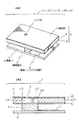
以下、図面を参照して本発明の実施形態の幾つかについて説明する。図1(a)は本発明を適用した第1の実施形態のインクジェットプリンタヘッド1の構成を示す斜視図、図1(b)は同実施形態のインクジェットプリンタヘッド1要部を簡略化して示す断面図である。
【0020】
この実施形態のインクジェットプリンタヘッド1は、概略において、プリンタヘッド本体6と圧電素子7および絶縁基板8によって構成される。更に、プリンタヘッド本体6は、ノズル穴となる小孔2を穿設した板状体3(以下、ノズルプレートという)と圧力室構成部材4および振動板5によって構成され、振動板5を振動させる圧電素子7を実装した絶縁基板8の表面には、圧電素子7に駆動用の電気信号を伝えるための薄膜トランジスタ回路9が一体的に形成されている。
【0021】
圧力室構成部材4の構造に関しては図11に示した従来例の圧力室構成部材103と実質的に同様である。
即ち、図1(b)に示される本実施形態の圧力室構成部材4においては、圧力室構成部材4を形成する枠体の内側部分に紙面厚み方向に所定の間隙を空けて図11の従来例と同様にして複数の障壁105が一体に設けられ、紙面厚み方向に隣接する二つの障壁105とノズルプレート3および振動板5で区画して形成される各々の空間によって複数の圧力室106が構成されている。インクプール107の形状も図11の従来例と同様であり、図1(b)に示される本実施形態の圧力室構成部材4においては、全ての障壁105の右端部を突き切るようにして紙面厚み方向に伸びるインクプール107が形成され、インクプール107内のインクは、紙面厚み方向に隣接する障壁105,105間の間隙で形成されるインク供給口112を通って各々の圧力室106に導かれる。
【0022】
図1(a)および図1(b)では、一つの圧力室106を形成するために必要とされる最小構成単位の部分に関してプリンタヘッド本体6の構成を記載しているが、実際には、この構成単位が図1(a)の前後左右方向、また、図1(b)においては紙面厚み方向と左右方向に多数重合してマトリクス状に一体成形されて一つのプリンタヘッド本体6を構成しており、一枚のノズルプレート3には多数の小孔2がマトリクス状に穿設されている(図2(c)参照)。
【0023】
プリンタヘッド本体6は、図1(a)および図1(b)に示されるように、ノズルプレート3や圧力室構成部材4および振動板5を形成する数枚(実施形態では3枚)の剛性板を重合して貼り合わせた積層構造を有し、ノズルプレート3における小孔2や圧力室構成部材4における障壁105,105間の間隙(圧力室106)およびインクプール107等はプレスによる打ち抜き加工等によって実現される。
【0024】
薄膜トランジスタ回路9は安価な絶縁基板を用いることのできる低温プロセスの多結晶シリコンで作成してもよいし、高温プロセスの多結晶シリコンまたはその他の薄膜トランジスタを用いてもよい。振動板5は、圧電素子7の共通電極も兼ねており、Ni板、あるいはその他の導電性を有する金属板を用いる。圧電素子7の材料にはチタン酸ジルコン酸鉛系セラミックスからなる材料、あるいは一般的な強誘電体が用いられる。
【0025】
次に、第1の実施形態のインクジェットプリンタヘッド1の製造方法について簡単に説明する。図2は本発明の第1の実施形態の製造工程を説明する図である。まず、図2(a)に示すように、減圧CVD法等により絶縁基板8上に薄膜トランジスタ回路9を形成する。
【0026】
次に、図2(b)に示すように、圧電素子7を絶縁基板8上の薄膜トランジスタ回路8に隣接する位置に実装する。この際、圧電素子7と絶縁基板8との間に球状のハンダを並べ、リフローにより、既に形成された薄膜トランジスタ回路9と圧電素子7とを電気的に接続する。接続後、圧電素子7の端面を研磨することにより、アライメントを行う。そして、研磨された圧電素子7の端面をダイシングすることにより前述した最小構成単位の各圧力室106に対応する各々の圧電素子7を個別化する。
【0027】
その後、図2(c)に示すように、振動板5,圧力室構成部材4およびノズルプレート3からなるプリンタヘッド本体6を圧電素子7上に実装する。
【0028】
次に、この製造方法により形成されたインクジェットプリンタヘッド1の動作について図1(b)を参照して説明する。インクはプリンタ本体からチューブを介して供給され、インクプール107およびインク供給口112を介して圧力室106に導かれる。また、電気信号はプリンタ本体から図示省略のFPCを介して絶縁基板8上の薄膜トランジスタ回路9に供給され、圧電素子7に印加される。なお、ダイシングにより最小構成単位に対応して個別化された各々の圧電素子7は各々に独立して機能する。そして、この信号に応じて圧電素子7が振動し、振動板5を変形させて、圧力室106内に圧力波を発生させる。この圧力波によってノズル穴となる小孔2からインク滴が吐出される。
【0029】
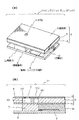
図3(a)は本発明の第2の実施形態のインクジェットプリンタヘッド11の構成を示す斜視図、図3(b)は同実施形態のインクジェットプリンタヘッド11の要部を簡略化して示す断面図である。
【0030】
この実施形態のインクジェットプリンタヘッド11は、薄膜トランジスタ回路9から発生する熱を伝導して排除する目的で設置された充填材10を備える点で前述した第1の実施形態と相違するが、他の部分の構成に関しては第1の実施形態と同様であるので、重複する構成部分に関しては図1(a)および図1(b)の説明で用いたものと同一の符号を付すにとどめ、説明は省略する。なお、この実施形態の充填材10は絶縁基板8とプリンタヘッド本体6の振動板5との間の離間距離を一定に保持するためのスペーサとしての機能を兼ね備える。
【0031】
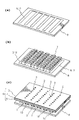
次に、本発明の第2の実施形態のインクジェットプリンタヘッド11の製造方法について簡単に説明する。図4は本発明の第2の実施形態の製造方法を説明する図である。まず、図4(a)に示すように、減圧CVD法等により絶縁基板8上に薄膜トランジスタ回路9を形成する。次に、図4(b)に示すように、圧電素子7を絶縁基板8上の薄膜トランジスタ回路9に隣接する位置に実装する。前記と同様、圧電素子7と絶縁基板8との間に球状のハンダを並べ、リフローにより、既に形成された薄膜トランジスタ回路9と圧電素子7とを電気的に接続する。接続後、圧電素子7の端面を研磨することにより、アライメントを行う。そして、研磨された圧電素子7の端面をダイシングすることにより、前記と同様、最小構成単位となる各々の圧電素子7を個別化する。
【0032】
その後、図4(c)に示すように薄膜トランジスタ回路9を覆う部分に充填材10を実装する。この充填材10の材質に関してはアルミ等、熱伝導性のよい金属が用いられる。そして、最終的に、振動板5,圧力室構成部材4およびノズルプレート3からなるプリンタヘッド本体6を圧電素子7上に実装する。
【0033】
この製造方法により製造されたインクジェットプリンタヘッド11の動作に関しては、前述した第1の実施形態と同様である。従って、本実施形態で用いる薄膜トランジスタ回路9は前述した第1の実施形態の場合と同様、安価な絶縁基板を用いた低温プロセスの多結晶シリコンで作成してもよいし、また、高温プロセスの多結晶シリコンやその他の薄膜トランジスタを用いてもよい。
【0034】
この実施形態によれば、インクジェットプリンタヘッド11の動作中に薄膜トランジスタ回路9で発生する熱は充填材10によって吸収され、大気中に放出されるので、高密度化によって生じる回路の温度上昇を抑制することができる。
【0035】
図5(a)は本発明の第3の実施形態のインクジェットプリンタヘッド12の構成を示す斜視図、図5(b)は同実施形態のインクジェットプリンタヘッド12の要部を簡略化して示す断面図である。
【0036】
この実施形態のインクジェットプリンタヘッド12は、薄膜トランジスタ回路9と共にアンプ回路13を一体に形成した点で前述した第1の実施形態と相違するが、他の部分の構成に関しては前述した第1の実施形態と同様であるので、重複する構成部分に関しては図1(a)および図1(b)の説明で用いたものと同一の符号を付すにとどめ、説明は省略する。
【0037】
アンプ回路13は薄膜トランジスタ9と同様、安価な絶縁基板を用いることのできる低温プロセスの多結晶シリコンで作成してもよいし、高温プロセスの多結晶シリコンまたはその他の薄膜トランジスタを用いてもよい。
【0038】
薄膜トランジスタ9と共にアンプ回路13が形成されているので、前述した第1の実施形態以上に回路構成の高密度化が達成される。
【0039】
次に、本発明の第3の実施形態のインクジェットプリンタヘッド12の製造方法について簡単に説明する。図6は本発明の第3の実施例の製造工程を説明する図である。まず、図6(a)に示すように絶縁基板8上に薄膜トランジスタ回路9およびアンプ回路13を形成する。
【0040】
次に、図6(b)に示すように、圧電素子7を絶縁基板8上の薄膜トランジスタ回路9およびアンプ回路13に隣接する位置に実装する。この際、圧電素子7と絶縁基板8上との間に球状のハンダを並べ、リフローにより、既に形成された薄膜トランジスタ回路9およびアンプ回路13とを電気的に接続する。接続後、圧電素子7の端面を研磨することにより、アライメントを行う。そして、研磨された圧電素子7の端面をダイシングすることにより前述した最小構成単位となる各々の圧電素子7を個別化する。
【0041】
そして、図6(c)のように、振動板5,圧力室構成部材4およびノズルプレート3からなるプリンタヘッド本体6を圧電素子7上に実装する。
【0042】
次に、この製造方法により形成されたインクジェットプリンタヘッド12の動作について図5(b)を参照して説明する。インクはプリンタ本体からチューブを介して供給され、インクプール107に充填され、インク供給口112を介して圧力室106に導かれる。また、電気信号はプリンタ本体から図示省略のFPCを介して絶縁基板8上の薄膜トランジスタ回路9に供給され、アンプ回路13によって増幅されて圧電素子7に印加される。そして、この信号に応じて圧電素子7が振動し、振動板5を変形させて、圧力室106内に圧力波を発生させる。この圧力波によってノズル穴となる小孔2からインク滴が吐出される。
【0043】
図7(a)は本発明の第4の実施形態のインクジェットプリンタヘッド14の構成を示す斜視図、図7(b)は同実施形態のインクジェットプリンタヘッド14の要部を簡略化して示す断面図である。
【0044】
この実施形態のインクジェットプリンタヘッド14は、薄膜トランジスタ回路9およびアンプ回路13から発生する熱を伝導し排除する充填材10が設置されている点で前述した第3の実施形態と相違するが、他の部分の構成に関しては前述した第3の実施形態と同様であるので、重複する構成部分に関しては図5(a)および図5(b)の説明で用いたものと同一の符号を付すにとどめ、説明は省略する。
【0045】
次に、本発明の第4の実施形態の製造方法について簡単に説明する。図8は本発明の第4の実施形態の製造工程を簡単に説明する図である。まず、図8(a)に示すように、絶縁基板8上に薄膜トランジスタ回路9およびアンプ回路13を形成する。
【0046】
次に、図8(b)に示すように、圧電素子7を絶縁基板8上の薄膜トランジスタ回路9およびアンプ回路13に隣接する位置に実装する。この際、圧電素子7と絶縁基板8との間に球状のハンダを並べ、リフローにより、既に形成された薄膜トランジスタ回路9およびアンプ回路13と圧電素子7とを電気的に接続する。接続後、圧電素子7の端面を研磨することにより、アライメントを行う。そして、研磨された圧電素子7の端面をダイシングすることにより前述した最小構成単位に対応する各々の圧電素子7を個別化する。
【0047】
その後、図8(c)に示すように薄膜トランジスタ回路9およびアンプ13を覆う部分に充填材10を実装する。この充填材10の材質に関しては、前述した第2の実施形態の場合と同様、アルミ等、熱伝導性の良い金属が用いられる。そして、最終的に、振動板5,圧力室構成部材4およびノズルプレート3からなるプリンタヘッド本体6を圧電素子7上に実装する。
【0048】
この製造方法により形成されたインクジェットプリンタヘッド14の動作は前述した第3の実施形態のものと同様であり、また、回路の温度上昇の抑制効果に関しては前述した第2の実施形態のものと同様である。本実施形態で用いる薄膜トランジスタ回路9およびアンプ回路13は、前述した各実施形態と同様、安価な絶縁基板を用いた低温プロセスの多結晶シリコンで作成してもよいし、また、高温プロセスの多結晶シリコンやその他の薄膜トランジスタを用いてもよい。
【0049】
図9は本発明の第5の実施形態のインクジェットプリンタヘッド15の構成の要部を簡略化して示す断面図である。本実施形態のインクジェットプリンタヘッド15においては、絶縁基板8において圧電素子7と反対側の面に薄膜トランジスタ回路9とアンプおよびバッファ回路17を形成し、絶縁基板8の端面に導体金属からなる電気接続16を設けて薄膜トランジスタ回路9とアンプおよびバッファ回路17を圧電素子7に電気的に接続し、更に、薄膜トランジスタ回路9とアンプおよびバッファ回路17の上に放熱板18を設置するようにしている。
【0050】
電気接続16の部分の材質は銀ペースト、銀パラジウムペースト、あるいはその他の導体金属を用い、また、放熱板18の材質については、アルミ等、熱伝導性のよい金属を用いる。薄膜トランジスタ回路9とアンプおよびバッファ回路17を絶縁基板8の裏面に形成するようにしているので、これらのものを絶縁基板8の表面に形成する場合のように圧電素子7の設置面を避けて同一平面上に配備する必要はなく、絶縁基板8自体の実装面積を小さくできる。また、薄膜トランジスタ回路9とアンプおよびバッファ回路17から発生する熱を放熱板18によって強制的に排除することができるので、より安定した動作を達成することができる。
【0051】
次に、本発明の第5の実施形態の製造方法について説明する。まず、絶縁基板8の裏面に薄膜トランジスタ回路9とアンプおよびバッファ回路17を形成する。次に絶縁基板8の薄膜トランジスタ回路9とアンプおよびバッファ回路17を覆う部分に放熱板18を実装する。そして、絶縁基板8における薄膜トランジスタ回路9とアンプおよびバッファ回路17と反対の面、つまり、絶縁基板8の表側の面に圧電素子7を実装する。その後、圧電素子7の端面を研磨することにより、アライメントを行う。そして、研磨された圧電素子7の端面をダイシングすることにより前述した最小構成単位に対応する各々の圧電素子7を個別化する。
【0052】
裏面側の薄膜トランジスタ回路9とアンプおよびバッファ回路17と表側の圧電素子7との電気的接続については、例えば、絶縁基板8の側面に銀ペーストを吹き付ける等の手段により達成する。そして、最終的に、振動板5,圧力室構成部材4およびノズルプレート3からなるプリンタヘッド本体6を圧電素子7上に実装する。
【0053】
次に、この製造方法により形成されたインクジェットプリンタヘッド15の動作について図9を参照して説明する。インクはプリンタ本体からチューブを介して供給され、インクプール107に充填される。また、電気信号はプリンタ本体から図示省略のFPCを介して絶縁基板8上の薄膜トランジスタ回路9に供給され、アンプおよびバッファ回路13のアンプにより増幅される。そして、電気接続16を通って、上面側の圧電素子7に印加される。そして、この信号に応じて圧電素子7が振動し、振動板5を変形させて、圧力室12内に圧力波を発生させる。この圧力波によってノズル穴となる小孔2からインク滴が吐出される。
【0054】
本発明の第5の実施形態で用いる薄膜トランジスタ回路9とアンプおよびバッファ回路17は、これまでに述べてきた各実施形態と同様、安価な絶縁基板を用いた低温プロセスの多結晶シリコンで作成してもよいし、また、高温プロセスの多結晶シリコンやその他の薄膜トランジスタを用いてもよい。
【0055】
そして、インクジェットプリンタヘッド15の動作中に薄膜トランジスタ回路9やアンプおよびバッファ回路17で発生する熱は放熱板18によって吸収され、大気中に放出されるので、高密度化によって生じる回路の温度上昇を抑制することができる。
【0056】
図10は本発明の第6の実施形態のインクジェットプリンタヘッド19の要部を簡略化して示す断面図である。
【0057】
この実施形態のインクジェットプリンタヘッド19では、絶縁基板8の表面に一体に形成した薄膜トランジスタ回路9およびアンプ回路13の上に更に保護膜20が形成され、圧電素子7は保護膜20の上に実装されている。薄膜トランジスタ回路9およびアンプ回路13と圧電素7との間の電気的な接続は、例えば、スパッタ法等により保護膜20を貫通してアルミあるいは導電性の金属でコンタクト20を形成させることにより達成される。保護膜20の材質としては有機系の薄膜が用いられる。
【0058】
次に、本発明の第6の実施形態の製造方法について簡単に説明する。まず、絶縁基板8上に薄膜トランジスタ回路9とアンプ回路13および保護膜20を形成する。そして、保護膜20にコンタクトホールを開け、アルミ、あるいは導電性の金属を利用したスパッタ法によりコンタクト21を形成する。次に、保護膜20上のコンタクト21に合わせて、圧電素子7を実装する。この際、圧電素子7とコンタクト21の接触面に球状のハンダを並べ、リフローにより、既に形成された薄膜トランジスタ回路9およびアンプ回路13と圧電素子7とを電気的に接続する。その後、圧電素子7の端面を研磨することにより、アライメントを行い、更に、研磨された圧電素子7の端面をダイシングすることにより圧電素子7を個別化し、最後に、振動板5,圧力室構成部材4およびノズルプレート3からなるプリンタヘッド本体6を圧電素子7上に実装する。
【0059】
次に、この製造方法により形成されたインクジェットプリンタヘッド19の動作について図10を参照して説明する。インクはプリンタ本体からチューブを介して供給され、インクプール107に充填される。また、電気信号はプリンタ本体から図示省略のFPCを介して絶縁基板8上の薄膜トランジスタ回路9に供給され、アンプ回路13で増幅された後、コンタクト21を経て圧電素子7に印加される。そして、この信号に応じて圧電素子7が振動し、振動板5を変形させて、圧力室12内に圧力波を発生させる。この圧力波によってノズル穴となる小孔2からインク滴が吐出される。
【0060】
本発明の第6の実施形態で用いる薄膜トランジスタ回路9およびアンプ回路13は、前述した各実施形態と同様、安価な絶縁基板を用いた低温プロセスの多結晶シリコンで作成してもよいし、また、高温プロセスの多結晶シリコンやその他の薄膜トランジスタを用いてもよい。
【0061】
【発明の効果】
本発明のインクジェットプリンタヘッドは、同一絶縁基板上に圧電素子やトランジスタ等の駆動回路を形成し、かつ、ノズルにおけるインクの吐出方向に重合して一体化することによってノズルや回路の高密度実装を実現したので、多数のノズルをマトリクス状に高密度で配備することが容易となり、印刷速度の高速化や高画質印刷が実現される。
【図面の簡単な説明】
【図1】図1(a)は本発明を適用した第1の実施形態の構成を示す斜視図、図1(b)は同実施形態の要部を簡略化して示す断面図である。
【図2】同実施形態の製造工程を図2(a),図2(b),図2(c)の順で説明する図である。
【図3】図3(a)は本発明を適用した第2の実施形態の構成を示す斜視図、図3(b)は同実施形態の要部を簡略化して示す断面図である。
【図4】同実施形態の製造工程を図4(a),図4(b),図4(c)の順で説明する図である。
【図5】図5(a)は本発明を適用した第3の実施形態の構成を示す斜視図、図5(b)は同実施形態の要部を簡略化して示す断面図である。
【図6】同実施形態の製造工程を図6(a),図6(b),図6(c)の順で説明する図である。
【図7】図7(a)は本発明を適用した第4の実施形態の構成を示す斜視図、図7(b)は同実施形態の要部を簡略化して示す断面図である。
【図8】同実施形態の製造工程を図8(a),図8(b),図8(c)の順で説明する図である。
【図9】本発明を適用した第5の実施形態の要部を簡略化して示す断面図である。
【図10】本発明を適用した第6の実施形態の要部を簡略化して示す断面図である。
【図11】圧電素子を用いてインク滴を吐出させる従来のインクジェットプリンタヘッドの構成の概略について一例を挙げて模式的に示す断面図である。
【図12】従来のインクジェットプリンタヘッドのインク滴吐出動作に関わる機能の概略について示す機能ブロック図である。
【符号の説明】
1 インクジェットプリンタヘッド
2 小孔(ノズル穴)
3 板状体(ノズルプレート)
4 圧力室構成部材
5 振動板
6 プリンタヘッド本体
7 圧電素子
8 絶縁基板
9 薄膜トランジスタ回路
10 充填材
11 インクジェットプリンタヘッド
12 インクジェットプリンタヘッド
13 アンプ回路
14 インクジェットプリンタヘッド
15 インクジェットプリンタヘッド
16 電気接続
17 アンプおよびバッファ回路
18 放熱板
19 インクジェットプリンタヘッド
20 保護膜
21 コンタクト
105 障壁
106 圧力室
107 インクプール
112 インク供給口[0001]
BACKGROUND OF THE INVENTION
The present invention relates to an improvement of an ink jet printer head that records characters and images by causing minute droplets to fly onto a recording medium such as paper.
[0002]
[Prior art]
FIG. 11 is a cross-sectional view schematically showing an example of the configuration of a conventional ink jet printer head that ejects ink droplets using a piezoelectric element, and FIG. 12 is an overview of functions related to ink droplet ejection operations. It is a functional block diagram shown.
[0003]
As shown in FIG. 11, a conventional ink
[0004]
In addition, an
[0005]
A plurality of
[0006]
As shown in FIG. 12, the ink in the
[0007]
[Problems to be solved by the invention]
In recent years, in the field of ink jet printers, technical problems such as high printing speed and high image quality printing have become problems. First, as means for realizing high speed, there is an increase in the number of nozzles of the ink jet printer head. In order to achieve high image quality, it is desired to change the size of the ink droplets ejected by changing the electrical signal supplied to the piezoelectric element and to change the size of the dots attached to the paper surface. A high-density ink jet printer head is required to satisfy both of these requirements.
[0008]
However, if the number of nozzles is increased or the function of changing the electrical signal supplied to the piezoelectric element is provided, the number of required drive circuits is also redundant and the wiring capacity increases. For example, as shown in FIG. 12, when the substrate on which the
[0009]
Further, it is possible to consider a means in which connection terminals are provided on different substrates, for example, the
[0010]
The driving signal sent from the printer
[0011]
OBJECT OF THE INVENTION
Therefore, an object of the present invention is to provide an ink jet printer head suitable for high-speed printing and high-quality printing by increasing the wiring and circuit configuration.
[0012]
[Means for Solving the Problems]
According to the present invention, a nozzle and a vibration plate are provided in a pressure chamber for storing ink, and the vibration plate is vibrated by a piezoelectric element driven by an electric signal to eject ink droplets from the nozzle. A print head body comprising a nozzle plate in which a plurality of nozzles are arranged in a matrix, a pressure chamber constituting member that constitutes a pressure chamber corresponding to the plurality of nozzles, and a diaphragm And the piezoelectric element Thin film transistor for supplying electrical signals A circuit was formed and the piezoelectric element was mounted The object is achieved by a structure in which an insulating substrate is integrally arranged in the direction of ink discharge in the nozzle so that the pressure chamber corresponds to the piezoelectric element via the diaphragm. did.
For supplying electrical signals to piezoelectric elements Transistor circuit The thin film Transistor circuit By forming the circuit structure, the circuit configuration can be densified. Also this thin film Transistor circuit By deploying together with piezoelectric elements on an insulating substrate Transistor circuit There is no need for a dedicated board, Transistor circuit The wiring capacity between the two is also reduced.
As a result, it becomes easy to arrange a large number of nozzles at a high density, and a high printing speed and high image quality printing are realized.
[0013]
In addition, when an amplifier circuit that amplifies an electrical signal and transmits it to the piezoelectric element is required, this amplifier circuit is also connected to the thin film. Transistor circuit At the same time, it is arranged integrally on the insulating substrate.
As a result of providing the amplifier circuit on the piezoelectric element side, it is not necessary to provide a large number of amplifier circuits on the printer body side, and no heat sink fins for cooling on the printer body side are required, thereby reducing the size of the entire inkjet printer. .
[0014]
Thin film Transistor circuit The amplifier circuit can be formed of, for example, polycrystalline silicon.
[ 0015 ]
A pressure chamber is integrally provided on the piezoelectric element via the diaphragm. In configuration A plate-like body having small holes is provided on the surface of the pressure chamber opposite to the diaphragm, and nozzles are formed by the small holes, thereby realizing high-density deployment of the nozzles.
[0016]
Furthermore, a thin film is formed on the same surface as the surface on which the piezoelectric element is mounted on the insulating substrate. Transistor circuit The Formation When the pressure chamber and the insulating substrate, that is, the pressure chamber and the thin film Transistor circuit A filler with high thermal conductivity is interposed between the filler and the filler to serve as a spacer between the insulating substrate and the print head body. Transistor circuit By forcibly removing the heat generated from the heat generation, the heat generation problem associated with the higher density of the circuit configuration is solved. Moreover, as a result of the filler acting as a spacer, the separation distance between the insulating substrate and the printer head main body is also kept constant.
[0017]
In addition, a thin film is formed on the insulating substrate so as to overlap with the piezoelectric element on the surface opposite to the surface on which the piezoelectric element is mounted. Transistor circuit The Formation The piezoelectric element and thin film located on the front and back of the insulating substrate. Transistor circuit Are connected by a conductive metal. Thin film using the surface opposite to the surface on which the piezoelectric element is mounted, that is, the back surface of the insulating substrate on which the piezoelectric element is not mounted Transistor circuit By arranging the above, it becomes possible to further reduce the area of the insulating substrate and further to arrange the nozzles at a high density.
[0018]
Thin film on the surface opposite to the surface on which the piezoelectric element is mounted Transistor circuit If the is installed, the surface opposite to the surface on which the piezoelectric element is mounted, that is, the thin film Transistor circuit The Formation Install a heat sink on the surface of the Transistor circuit By forcibly removing the heat generated from the circuit, the heat generation problem associated with higher circuit density is solved.
[ 0019 ]
DETAILED DESCRIPTION OF THE INVENTION
Hereinafter, some embodiments of the present invention will be described with reference to the drawings. FIG. 1A is a perspective view showing a configuration of an inkjet printer head 1 according to a first embodiment to which the present invention is applied, and FIG. 1B is a cross-sectional view showing a main part of the inkjet printer head 1 according to the embodiment in a simplified manner. FIG.
[ 0020 ]
The ink jet printer head 1 of this embodiment is generally constituted by a printer head
[ 0021 ]
The structure of the pressure
That is, in the pressure
[ 0022 ]
In FIG. 1A and FIG. 1B, the configuration of the
[ 0023 ]
As shown in FIGS. 1A and 1B, the printer head
[ 0024 ]
The thin film transistor circuit 9 may be made of low-temperature process polycrystalline silicon that can use an inexpensive insulating substrate, or may use high-temperature process polycrystalline silicon or other thin film transistors. The vibration plate 5 also serves as a common electrode for the
[ 0025 ]
Next, a method for manufacturing the ink jet printer head 1 of the first embodiment will be briefly described. FIG. 2 is a diagram for explaining a manufacturing process according to the first embodiment of the present invention. First, as shown in FIG. 2A, a thin film transistor circuit 9 is formed on an insulating
[ 0026 ]
Next, as shown in FIG. 2B, the
[ 0027 ]
Thereafter, as shown in FIG. 2C, the
[ 0028 ]
Next, the operation of the ink jet printer head 1 formed by this manufacturing method will be described with reference to FIG. Ink is supplied from the printer main body via a tube, and is guided to the
[ 0029 ]
FIG. 3A is a perspective view showing the configuration of the ink
[ 0030 ]
The ink
[ 0031 ]
Next, a method for manufacturing the ink
[ 0032 ]
Thereafter, as shown in FIG. 4C, the
[ 0033 ]
The operation of the
[ 0034 ]
According to this embodiment, the heat generated in the thin film transistor circuit 9 during the operation of the
[ 0035 ]
FIG. 5A is a perspective view showing a configuration of an ink
[ 0036 ]
The
[ 0037 ]
Similarly to the thin film transistor 9, the
[ 0038 ]
Since the
[ 0039 ]
Next, a method for manufacturing the
[ 0040 ]
Next, as shown in FIG. 6B, the
[ 0041 ]
Then, as shown in FIG. 6C, the
[ 0042 ]
Next, the operation of the ink
[ 0043 ]
FIG. 7A is a perspective view showing a configuration of an
[ 0044 ]
The
[ 0045 ]
Next, a manufacturing method according to the fourth embodiment of the present invention will be briefly described. FIG. 8 is a diagram for briefly explaining the manufacturing process of the fourth embodiment of the present invention. First, as shown in FIG. 8A, the thin film transistor circuit 9 and the
[ 0046 ]
Next, as shown in FIG. 8B, the
[ 0047 ]
Thereafter, as shown in FIG. 8C, the
[ 0048 ]
The operation of the
[ 0049 ]
FIG. 9 is a cross-sectional view schematically showing the main part of the configuration of the
[ 0050 ]
Silver paste, silver palladium paste, or other conductive metal is used as the material of the
[ 0051 ]
Next, a manufacturing method according to the fifth embodiment of the present invention will be described. First, the thin film transistor circuit 9 and the amplifier and buffer circuit 17 are formed on the back surface of the insulating
[ 0052 ]
The electrical connection between the thin film transistor circuit 9 on the back side, the amplifier / buffer circuit 17 and the
[ 0053 ]
Next, the operation of the
[ 0054 ]
The thin film transistor circuit 9 and the amplifier and buffer circuit 17 used in the fifth embodiment of the present invention are made of polycrystalline silicon of a low temperature process using an inexpensive insulating substrate, as in the embodiments described so far. Alternatively, high-temperature process polycrystalline silicon or other thin film transistors may be used.
[ 0055 ]
The heat generated in the thin film transistor circuit 9 and the amplifier and buffer circuit 17 during the operation of the ink
[ 0056 ]
FIG. 10 is a cross-sectional view schematically showing the main part of an ink
[ 0057 ]
In the ink
[ 0058 ]
Next, a manufacturing method according to the sixth embodiment of the present invention will be briefly described. First, the thin film transistor circuit 9, the
[ 0059 ]
Next, the operation of the ink
[ 0060 ]
The thin film transistor circuit 9 and the
[ 0061 ]
【The invention's effect】
The inkjet printer head of the present invention forms a drive circuit such as a piezoelectric element or a transistor on the same insulating substrate. And superimposing in the direction of ink ejection at the nozzle. Has achieved high-density mounting of nozzles and circuits. In a matrix It becomes easy to deploy with high density, and high-speed printing and high-quality printing are realized.
[Brief description of the drawings]
FIG. 1A is a perspective view showing a configuration of a first embodiment to which the present invention is applied, and FIG. 1B is a cross-sectional view showing a main part of the embodiment in a simplified manner.
FIG. 2 is a diagram illustrating the manufacturing process of the embodiment in the order of FIG. 2A, FIG. 2B, and FIG. 2C;
FIG. 3A is a perspective view showing a configuration of a second embodiment to which the present invention is applied, and FIG. 3B is a cross-sectional view showing a simplified main portion of the embodiment.
4 is a diagram for explaining the manufacturing process of the embodiment in the order of FIG. 4A, FIG. 4B, and FIG. 4C;
FIG. 5A is a perspective view showing a configuration of a third embodiment to which the present invention is applied, and FIG. 5B is a cross-sectional view showing a simplified main portion of the embodiment.
6 is a diagram for explaining the manufacturing process of the embodiment in the order of FIG. 6A, FIG. 6B, and FIG. 6C;
FIG. 7A is a perspective view showing a configuration of a fourth embodiment to which the present invention is applied, and FIG. 7B is a cross-sectional view showing a simplified main portion of the embodiment.
FIG. 8 is a diagram for explaining the manufacturing process of the embodiment in the order of FIG. 8A, FIG. 8B, and FIG. 8C;
FIG. 9 is a cross-sectional view schematically showing a main part of a fifth embodiment to which the present invention is applied.
FIG. 10 is a simplified cross-sectional view showing a main part of a sixth embodiment to which the present invention is applied.
FIG. 11 is a cross-sectional view schematically showing an example of the configuration of a conventional inkjet printer head that ejects ink droplets using a piezoelectric element.
FIG. 12 is a functional block diagram showing an outline of functions related to an ink droplet ejection operation of a conventional inkjet printer head.
[Explanation of symbols]
1 Inkjet printer head
2 Small holes (nozzle holes)
3 Plate (nozzle plate)
4 Pressure chamber components
5 Diaphragm
6 Printer head body
7 Piezoelectric elements
8 Insulating substrate
9 Thin film transistor circuit
10 Filler
11 Inkjet printer head
12 Inkjet printer head
13 Amplifier circuit
14 Inkjet printer head
15 Inkjet printer head
16 Electrical connection
17 Amplifier and buffer circuit
18 Heat sink
19 Inkjet printer head
20 Protective film
21 Contact
105 Barrier
106 Pressure chamber
107 Ink pool
112 Ink supply port
Claims (7)
複数のノズルがマトリクス状に配置されたノズルプレートと、前記複数のノズルに対応して圧力室を構成する圧力室構成部材と振動板とからなるプリントヘッド本体と、前記圧電素子に電気信号を供給するための薄膜トランジスタ回路を形成すると共に前記圧電素子を実装した絶縁基板とが、前記振動板を介し前記圧電素子上に前記圧力室が対応するよう前記ノズルにおけるインクの吐出方向に重合して一体に配備されていることを特徴とするインクジェットプリンタヘッド。 An inkjet printer head configured to provide a nozzle and a vibration plate in a pressure chamber for storing ink, and to vibrate the vibration plate by a piezoelectric element driven by an electric signal to discharge ink droplets from the nozzle,
Supply and a nozzle plate in which a plurality of nozzles are arranged in a matrix, and a print head body comprising a pressure chamber constituting member and the diaphragm constituting the pressure chambers corresponding to said plurality of nozzles, the electrical signal to said piezoelectric element And an insulating substrate on which the piezoelectric element is mounted and integrated with the pressure chamber on the piezoelectric element via the diaphragm in the direction of ink discharge in the nozzle. An inkjet printer head, wherein the inkjet printer head is provided.
Priority Applications (1)
| Application Number | Priority Date | Filing Date | Title |
|---|---|---|---|
| JP9984099A JP3667553B2 (en) | 1999-04-07 | 1999-04-07 | Inkjet printer head |
Applications Claiming Priority (1)
| Application Number | Priority Date | Filing Date | Title |
|---|---|---|---|
| JP9984099A JP3667553B2 (en) | 1999-04-07 | 1999-04-07 | Inkjet printer head |
Related Child Applications (1)
| Application Number | Title | Priority Date | Filing Date |
|---|---|---|---|
| JP2002105107A Division JP2002307680A (en) | 2002-04-08 | 2002-04-08 | Ink jet printer head and driving circuit board |
Publications (2)
| Publication Number | Publication Date |
|---|---|
| JP2000289196A JP2000289196A (en) | 2000-10-17 |
| JP3667553B2 true JP3667553B2 (en) | 2005-07-06 |
Family
ID=14258009
Family Applications (1)
| Application Number | Title | Priority Date | Filing Date |
|---|---|---|---|
| JP9984099A Expired - Lifetime JP3667553B2 (en) | 1999-04-07 | 1999-04-07 | Inkjet printer head |
Country Status (1)
| Country | Link |
|---|---|
| JP (1) | JP3667553B2 (en) |
-
1999
- 1999-04-07 JP JP9984099A patent/JP3667553B2/en not_active Expired - Lifetime
Also Published As
| Publication number | Publication date |
|---|---|
| JP2000289196A (en) | 2000-10-17 |
Similar Documents
| Publication | Publication Date | Title |
|---|---|---|
| JP4221929B2 (en) | Multi-nozzle ink jet head | |
| JPH10278282A (en) | Method of manufacturing inkjet head | |
| US8851603B2 (en) | Driving device for driving liquid discharge head, recording apparatus, and recording method | |
| JP2001138518A (en) | Printing head equipped with large-sized nozzle array for thermal ink jet | |
| TWI273982B (en) | Droplet ejection head and droplet ejection apparatus | |
| US7478896B2 (en) | Ink jet head | |
| CN113939405A (en) | Liquid ejection head and recording apparatus | |
| JP2004181798A (en) | Ink jet type recording head and ink jet type recording device using the same | |
| JP2001113700A (en) | Inkjet head | |
| JP4569151B2 (en) | Inkjet printer head unit, inkjet printer, and signal transmission board used therefor | |
| JP2008074091A (en) | Liquid transfer device and method for manufacturing liquid transfer device | |
| JP3584952B2 (en) | Actuator unit for laminated ink jet recording head and ink jet recording head using the same | |
| JP3221470B2 (en) | Ink jet head and method of manufacturing the same | |
| JP3667553B2 (en) | Inkjet printer head | |
| JP2004160941A (en) | Droplet ejection head, inkjet recording device | |
| JP2002307680A (en) | Ink jet printer head and driving circuit board | |
| JP4507782B2 (en) | Inkjet recording device | |
| JP3611782B2 (en) | Inkjet head | |
| JP4639957B2 (en) | Droplet discharge head and droplet discharge apparatus | |
| JP5691320B2 (en) | Ink jet recording head and ink jet recording apparatus | |
| JP2000071448A (en) | Ink jet recording device | |
| JP2011079246A (en) | Inkjet recording head | |
| JP2009083242A (en) | Droplet discharge head | |
| JPH11291493A (en) | Ink jet recording head | |
| JP2005131948A (en) | Head module, liquid ejection head, liquid ejection apparatus, head module manufacturing method, and liquid ejection head manufacturing method |
Legal Events
| Date | Code | Title | Description |
|---|---|---|---|
| A02 | Decision of refusal |
Free format text: JAPANESE INTERMEDIATE CODE: A02 Effective date: 20020212 |
|
| A521 | Written amendment |
Free format text: JAPANESE INTERMEDIATE CODE: A523 Effective date: 20050301 |
|
| RD01 | Notification of change of attorney |
Free format text: JAPANESE INTERMEDIATE CODE: A7421 Effective date: 20050301 |
|
| A61 | First payment of annual fees (during grant procedure) |
Free format text: JAPANESE INTERMEDIATE CODE: A61 Effective date: 20050406 |
|
| R150 | Certificate of patent or registration of utility model |
Free format text: JAPANESE INTERMEDIATE CODE: R150 |
|
| FPAY | Renewal fee payment (event date is renewal date of database) |
Free format text: PAYMENT UNTIL: 20080415 Year of fee payment: 3 |
|
| FPAY | Renewal fee payment (event date is renewal date of database) |
Free format text: PAYMENT UNTIL: 20090415 Year of fee payment: 4 |
|
| FPAY | Renewal fee payment (event date is renewal date of database) |
Free format text: PAYMENT UNTIL: 20100415 Year of fee payment: 5 |
|
| FPAY | Renewal fee payment (event date is renewal date of database) |
Free format text: PAYMENT UNTIL: 20110415 Year of fee payment: 6 |
|
| FPAY | Renewal fee payment (event date is renewal date of database) |
Free format text: PAYMENT UNTIL: 20120415 Year of fee payment: 7 |
|
| FPAY | Renewal fee payment (event date is renewal date of database) |
Free format text: PAYMENT UNTIL: 20120415 Year of fee payment: 7 |
|
| FPAY | Renewal fee payment (event date is renewal date of database) |
Free format text: PAYMENT UNTIL: 20130415 Year of fee payment: 8 |
|
| FPAY | Renewal fee payment (event date is renewal date of database) |
Free format text: PAYMENT UNTIL: 20130415 Year of fee payment: 8 |
|
| S111 | Request for change of ownership or part of ownership |
Free format text: JAPANESE INTERMEDIATE CODE: R313113 |
|
| FPAY | Renewal fee payment (event date is renewal date of database) |
Free format text: PAYMENT UNTIL: 20130415 Year of fee payment: 8 |
|
| R350 | Written notification of registration of transfer |
Free format text: JAPANESE INTERMEDIATE CODE: R350 |
|
| FPAY | Renewal fee payment (event date is renewal date of database) |
Free format text: PAYMENT UNTIL: 20130415 Year of fee payment: 8 |
|
| FPAY | Renewal fee payment (event date is renewal date of database) |
Free format text: PAYMENT UNTIL: 20140415 Year of fee payment: 9 |
|
| R250 | Receipt of annual fees |
Free format text: JAPANESE INTERMEDIATE CODE: R250 |
|
| R250 | Receipt of annual fees |
Free format text: JAPANESE INTERMEDIATE CODE: R250 |
|
| R250 | Receipt of annual fees |
Free format text: JAPANESE INTERMEDIATE CODE: R250 |
|
| R250 | Receipt of annual fees |
Free format text: JAPANESE INTERMEDIATE CODE: R250 |
|
| R250 | Receipt of annual fees |
Free format text: JAPANESE INTERMEDIATE CODE: R250 |
|
| EXPY | Cancellation because of completion of term |