JP3665740B2 - Opening device for gas pressure vessel of airbag - Google Patents
Opening device for gas pressure vessel of airbag Download PDFInfo
- Publication number
- JP3665740B2 JP3665740B2 JP2000510621A JP2000510621A JP3665740B2 JP 3665740 B2 JP3665740 B2 JP 3665740B2 JP 2000510621 A JP2000510621 A JP 2000510621A JP 2000510621 A JP2000510621 A JP 2000510621A JP 3665740 B2 JP3665740 B2 JP 3665740B2
- Authority
- JP
- Japan
- Prior art keywords
- gas pressure
- pressure vessel
- opening device
- sealing element
- housing
- Prior art date
- Legal status (The legal status is an assumption and is not a legal conclusion. Google has not performed a legal analysis and makes no representation as to the accuracy of the status listed.)
- Expired - Fee Related
Links
- 238000007789 sealing Methods 0.000 claims description 35
- 239000002360 explosive Substances 0.000 claims description 14
- 239000007789 gas Substances 0.000 description 60
- 239000011888 foil Substances 0.000 description 6
- 239000001307 helium Substances 0.000 description 3
- 229910052734 helium Inorganic materials 0.000 description 3
- SWQJXJOGLNCZEY-UHFFFAOYSA-N helium atom Chemical compound [He] SWQJXJOGLNCZEY-UHFFFAOYSA-N 0.000 description 3
- XKRFYHLGVUSROY-UHFFFAOYSA-N Argon Chemical compound [Ar] XKRFYHLGVUSROY-UHFFFAOYSA-N 0.000 description 2
- IJGRMHOSHXDMSA-UHFFFAOYSA-N Atomic nitrogen Chemical compound N#N IJGRMHOSHXDMSA-UHFFFAOYSA-N 0.000 description 2
- 238000004519 manufacturing process Methods 0.000 description 2
- 239000000463 material Substances 0.000 description 2
- 229910052786 argon Inorganic materials 0.000 description 1
- 238000010276 construction Methods 0.000 description 1
- 238000004880 explosion Methods 0.000 description 1
- 230000002349 favourable effect Effects 0.000 description 1
- 239000011261 inert gas Substances 0.000 description 1
- 238000009434 installation Methods 0.000 description 1
- 239000000203 mixture Substances 0.000 description 1
- 229910052757 nitrogen Inorganic materials 0.000 description 1
- 229910052756 noble gas Inorganic materials 0.000 description 1
- 230000003068 static effect Effects 0.000 description 1
Images


Classifications
-
- B—PERFORMING OPERATIONS; TRANSPORTING
- B60—VEHICLES IN GENERAL
- B60R—VEHICLES, VEHICLE FITTINGS, OR VEHICLE PARTS, NOT OTHERWISE PROVIDED FOR
- B60R21/00—Arrangements or fittings on vehicles for protecting or preventing injuries to occupants or pedestrians in case of accidents or other traffic risks
- B60R21/02—Occupant safety arrangements or fittings, e.g. crash pads
- B60R21/16—Inflatable occupant restraints or confinements designed to inflate upon impact or impending impact, e.g. air bags
- B60R21/26—Inflatable occupant restraints or confinements designed to inflate upon impact or impending impact, e.g. air bags characterised by the inflation fluid source or means to control inflation fluid flow
- B60R21/268—Inflatable occupant restraints or confinements designed to inflate upon impact or impending impact, e.g. air bags characterised by the inflation fluid source or means to control inflation fluid flow using instantaneous release of stored pressurised gas
-
- F—MECHANICAL ENGINEERING; LIGHTING; HEATING; WEAPONS; BLASTING
- F17—STORING OR DISTRIBUTING GASES OR LIQUIDS
- F17C—VESSELS FOR CONTAINING OR STORING COMPRESSED, LIQUEFIED OR SOLIDIFIED GASES; FIXED-CAPACITY GAS-HOLDERS; FILLING VESSELS WITH, OR DISCHARGING FROM VESSELS, COMPRESSED, LIQUEFIED, OR SOLIDIFIED GASES
- F17C7/00—Methods or apparatus for discharging liquefied, solidified, or compressed gases from pressure vessels, not covered by another subclass
-
- F—MECHANICAL ENGINEERING; LIGHTING; HEATING; WEAPONS; BLASTING
- F17—STORING OR DISTRIBUTING GASES OR LIQUIDS
- F17C—VESSELS FOR CONTAINING OR STORING COMPRESSED, LIQUEFIED OR SOLIDIFIED GASES; FIXED-CAPACITY GAS-HOLDERS; FILLING VESSELS WITH, OR DISCHARGING FROM VESSELS, COMPRESSED, LIQUEFIED, OR SOLIDIFIED GASES
- F17C2201/00—Vessel construction, in particular geometry, arrangement or size
- F17C2201/01—Shape
- F17C2201/0104—Shape cylindrical
-
- F—MECHANICAL ENGINEERING; LIGHTING; HEATING; WEAPONS; BLASTING
- F17—STORING OR DISTRIBUTING GASES OR LIQUIDS
- F17C—VESSELS FOR CONTAINING OR STORING COMPRESSED, LIQUEFIED OR SOLIDIFIED GASES; FIXED-CAPACITY GAS-HOLDERS; FILLING VESSELS WITH, OR DISCHARGING FROM VESSELS, COMPRESSED, LIQUEFIED, OR SOLIDIFIED GASES
- F17C2205/00—Vessel construction, in particular mounting arrangements, attachments or identifications means
- F17C2205/03—Fluid connections, filters, valves, closure means or other attachments
- F17C2205/0302—Fittings, valves, filters, or components in connection with the gas storage device
- F17C2205/0323—Valves
- F17C2205/0332—Safety valves or pressure relief valves
-
- F—MECHANICAL ENGINEERING; LIGHTING; HEATING; WEAPONS; BLASTING
- F17—STORING OR DISTRIBUTING GASES OR LIQUIDS
- F17C—VESSELS FOR CONTAINING OR STORING COMPRESSED, LIQUEFIED OR SOLIDIFIED GASES; FIXED-CAPACITY GAS-HOLDERS; FILLING VESSELS WITH, OR DISCHARGING FROM VESSELS, COMPRESSED, LIQUEFIED, OR SOLIDIFIED GASES
- F17C2221/00—Handled fluid, in particular type of fluid
- F17C2221/01—Pure fluids
- F17C2221/016—Noble gases (Ar, Kr, Xe)
- F17C2221/017—Helium
-
- F—MECHANICAL ENGINEERING; LIGHTING; HEATING; WEAPONS; BLASTING
- F17—STORING OR DISTRIBUTING GASES OR LIQUIDS
- F17C—VESSELS FOR CONTAINING OR STORING COMPRESSED, LIQUEFIED OR SOLIDIFIED GASES; FIXED-CAPACITY GAS-HOLDERS; FILLING VESSELS WITH, OR DISCHARGING FROM VESSELS, COMPRESSED, LIQUEFIED, OR SOLIDIFIED GASES
- F17C2223/00—Handled fluid before transfer, i.e. state of fluid when stored in the vessel or before transfer from the vessel
- F17C2223/01—Handled fluid before transfer, i.e. state of fluid when stored in the vessel or before transfer from the vessel characterised by the phase
- F17C2223/0107—Single phase
- F17C2223/0123—Single phase gaseous, e.g. CNG, GNC
-
- F—MECHANICAL ENGINEERING; LIGHTING; HEATING; WEAPONS; BLASTING
- F17—STORING OR DISTRIBUTING GASES OR LIQUIDS
- F17C—VESSELS FOR CONTAINING OR STORING COMPRESSED, LIQUEFIED OR SOLIDIFIED GASES; FIXED-CAPACITY GAS-HOLDERS; FILLING VESSELS WITH, OR DISCHARGING FROM VESSELS, COMPRESSED, LIQUEFIED, OR SOLIDIFIED GASES
- F17C2270/00—Applications
- F17C2270/01—Applications for fluid transport or storage
- F17C2270/0165—Applications for fluid transport or storage on the road
- F17C2270/0181—Airbags
-
- Y—GENERAL TAGGING OF NEW TECHNOLOGICAL DEVELOPMENTS; GENERAL TAGGING OF CROSS-SECTIONAL TECHNOLOGIES SPANNING OVER SEVERAL SECTIONS OF THE IPC; TECHNICAL SUBJECTS COVERED BY FORMER USPC CROSS-REFERENCE ART COLLECTIONS [XRACs] AND DIGESTS
- Y10—TECHNICAL SUBJECTS COVERED BY FORMER USPC
- Y10T—TECHNICAL SUBJECTS COVERED BY FORMER US CLASSIFICATION
- Y10T137/00—Fluid handling
- Y10T137/1624—Destructible or deformable element controlled
- Y10T137/1632—Destructible element
- Y10T137/1774—With counterbalancing element
Landscapes
- Engineering & Computer Science (AREA)
- Mechanical Engineering (AREA)
- Physics & Mathematics (AREA)
- Fluid Mechanics (AREA)
- General Engineering & Computer Science (AREA)
- Air Bags (AREA)
- Safety Valves (AREA)
Description
【0001】
本発明は、ガス圧容器のための開口装置であって、ガス圧容器の排流穴に接続し、ガス圧容器と固定結合されているハウジングと、ハウジングの内部空間とガス圧容器の内部空間との間に配置され、ガス圧容器の排流穴を閉鎖することによりハウジングの内部空間をガス圧容器の内部空間に対し密封させている密封要素にして、ガス圧容器内のガス圧により密封要素に対して作用する開口力に抗するように加圧部材を介して対向支持部材に支持されている前記密封要素と、密封要素とは別個に支持される作動装置とを備え、作動装置が作動時に密封要素の支持を解消することにより、排流穴がガス圧容器内のガス圧により開口してエアバッグを膨らませるようにした前記開口装置に関する。
【0002】
この種の開口装置は、ドイツ連邦共和国特許公開第19540618号公報から知られている。ガス圧容器の排流穴は密封要素で閉鎖され、密封要素はガス力を支持するため加圧部材を介してハウジング固定の対向支持部材で支持されている。加圧部材には爆薬装填部が付設されており、爆薬装填部が点火すると対向支持部材が破損して、密封要素の支持が解消される。このとき密封要素はガス圧容器内のガス圧だけで破壊され、ハウジングに接続されているエアバッグは流出するガスにより膨らむ。
【0003】
ドイツ連邦共和国特許第19727047号公報からは、ガス圧蓄圧器を不活性ガスで充填すること、たとえば窒素、アルゴンおよびヘリウムのグループからなる少なくとも1種類のガスで充填することが知られている。充填されたガス圧容器は破裂ディスクにより閉鎖される。破裂ディスクはガス圧容器に溶接されており、爆薬装填部の爆発圧により開口する。
【0004】
充填されるガス圧容器は下請け業者により製造されて顧客に発送される。発送の準備が終わっているガス圧容器は、それぞれ爆薬装填部を備えた、作動準備完了状態にある開口装置を含んでいる。したがって製造、発送、最終組み立ての際には、開口装置の不慮の作動を回避するため、慎重な操作が必要である。
【0005】
さらに、エアバッグを機械的に損傷させずに急速にきちんと膨らませるには、ガス圧容器内に蓄積されているガスが特定の混合状態になければならないことが確認された。
【0006】
本発明の課題は、この種の開口装置において、製造、発送、最終組み立ての際に、開口装置の不慮の作動を回避することである。
【0007】
この課題は、本発明によれば、互いに対向する側において開口しているハウジングが、ガス圧容器と結合される本体を有し、本体の開口端面が本体とは別個に設けられる端面板により閉鎖可能であり、作動装置が、ハウジングとは別個に独立して取り付け可能なユニットとして一方の端面板で保持されていることにより解決される。
【0008】
本発明によれば、作動装置はハウジングとは別個に独立して取り付け可能なユニットとして実施されている。密封要素の支持が作動装置とは独立に安定であるため、作動装置なしでも開口装置をガス圧容器とともに事前に取り付けることができる。ハウジングは反対側で開いたままであるので、密封要素が不慮に開口しても、加圧状態にあるガスは同じ開口面積の反対側から流出し、よってスラスト力のない(schubneutral)反作用力だけが発生する。したがってガス圧容器はほとんど移動せず、或いは全く移動しないので、事前に取り付けて発送し、最終的に組み立てる場合、付加的なコストを要せずに高い安定性が得られる。作動装置は開口装置およびガス圧容器とは別個に事前に取り付けられる。最終取り付けのときにはじめてガス圧容器用の開口装置に作動装置を具備させて、装置全体が作動準備状態にもたらされる。しかしこの場合ガス圧容器は固定して取り付けられるので、排流ガスに発生するスラスト力が捕獲される。
【0009】
ハウジングを、ガス圧容器と連結され端面が開口した本体から形成するのが有利である。開口端面は端面板により閉鎖可能である。この場合、ハウジング本体は発送用に暫定的な端面板で閉鎖することができる。両端面板は同じ大きさの排流穴を有している。このように、ハウジング内での開口装置の損傷は確実に回避される。最終組み立ての際にはじめて、一方の端面板に取り付けた作動装置がハウジング本体に装着され、この場合、作動装置とは反対側の端面板はエアバッグの充填に必要な排流穴を有している。この端面板にエアバッグを固定するのが合目的である。
【0010】
作動装置の位置正確な取り付けを保証するため、ハウジング本体の端面の開口縁は端面板の受容溝に係合する。
本発明の他の構成は他の請求項、以下の説明および図面から明らかである。図面には、本発明のいくつかの実施形態が図示されている。
【0011】
図1に図示したガス圧容器1は、たとえば自動車に使用されるエアバッグ2を膨らませるために用いる。
図2と図3からわかるように、ガス圧容器1の中央の排流穴3には、ガス圧容器1と固定連結されているハウジング4が接続している。排流穴3はガス圧容器1の中心縦軸線48に同軸に位置しているのが有利である。ハウジング4の正確な構成は図1、図2および図7から明らかであり、他方図3ないし図6はハウジング4を概略的に図示したものであり、図8と図9はハウジングの変形実施形態を示したものである。
【0012】
ハウジング4は、特に図2に示すように中空の本体5を有している。中空の本体5は、互いに逆の側に位置している開口した端面6と7を備え、端面6と7は端面板8と9により閉鎖される。図1からわかるように端面板8と9は端面6と7よりも大きく形成されているので、端面板8と9は本体5から突出している。突出部分10には、タイロッド12を配置するための貫通穴11が設けられている。端面板8と9は大きさの点で同じであるように合目的に形成されているので、互いに逆の側にある端面板8と9の貫通穴11は互いに合同であり、それぞれのタイロッド12の配置を可能にしている。端面板を本体5に位置正確に取付けできるよう保証するため、端面板8と9の本体5側には、開口している端面6と7の縁14を受容する受容穴13が形成されている。端面6と7を閉鎖して端面板8と9を取り付けると、本体5の縁14はそれぞれの端面板の受容溝13に係合して、端面板のハウジング本体5への位置正確な取り付けを保証する。この配置構成により、タイロッド12の取り付けのため貫通穴11が互いに正確に整列した位置を占めることも保証されている。なおタイロッド12は端面板8,9の周方向に3本設けられている。そのうち1本のタイロッド12はガス圧容器1の中心縦軸線48とほぼ交差して、開口装置上方の加圧部材の延長上にある。他の2本のタイロッド12はガス圧容器1の首部に隣接するようにハウジング4の左右に位置している。これら3本のタイロッド12はすべて、端面板8と9に対して垂直なハウジング4の中心縦軸線45に平行に位置している。
【0013】
ガス圧容器1はほぼハウジング4の中心に開口しており、或いは図示した実施形態の場合横断面にて正方形に実施されているハウジング本体5のほぼ中心に開口している。ハウジング本体5の他の横断面形状も有利である(図8)。端面板8と9を取り外したときにスラスト力がないようにするため、ハウジング4またはその本体5は互いに逆の側の端面6,7で開口している。開口端面6,7は同じ面積であるのが有利である。各端面6,7の中心垂線はハウジング本体4またはハウジング4の中心縦軸線45と同軸である。ガス圧容器1の中心縦軸線48は、ハウジング4の中心縦軸線45と直角に交わっている。
【0014】
排流穴3は密封要素15により密封されている。密封要素15は、図示した実施形態では薄いフォイルとして形成されており、排流穴3のハウジング4とは逆の側においてガス圧容器1内に取り付けられている。密封要素15はフォイルエッジ16の領域で容器ハウジング17と圧密に結合されているのが有利である。フォイルエッジ16は、フォイルの材料に応じて容器ハウジング17と溶接または接着してよい。
【0015】
密封要素15は、ハウジング4側で支持ディスク18に当接している。支持ディスク18は排流穴3内に配置されている。この場合支持ディスク18は排流穴3の縁19と半径方向に遊びを持って位置しており、これにより、密封要素15により容器側で閉鎖されている環状隙間20が形成されている。この環状隙間20は逃がし弁を形成している。環状隙間20は密封要素15の材料との関連で次のように構成され、すなわち予め設定可能な限界圧のときに密封要素15がこの環状隙間の領域で破損し、その結果過圧が環状隙間20を介して逃がし制御され、しかも排流穴3自体が開口しないように構成されている。なお図8と図9は、環状隙間を設けていないガス圧容器を示している。
【0016】
支持ディスク18は、加圧部材21を介して、ハウジング固定の対向支持部材22で支持されているので、容器1内のガス圧によって密封要素15に作用する開口力が確実に捕獲される。この場合加圧部材21は、ボールヘッド状の端部23により支持ディスク18の対応する凹状の支持部24内にあり、加圧部材21の他端25はわずかに凹状のロック凹部26を有しており、このロック凹部26により加圧部材21は対向支持部材22を形成しているピン27に当接して簡単にロックが可能である。ピン27は、ハウジング本体5の対向する穴47で保持されている。加圧部材21の縦軸線28は支持ディスク18または密封要素15に対して垂直であり、ピン27の軸線を通っており、ガス圧容器1の中心縦軸線48に同軸に位置している。
【0017】
縦長の、有利には筒状の加圧部材21の縦軸線28に対して交差するように作動装置30が配置されている。作動装置30は、図2が示すように、ハウジングの端面板9に取り付けられ、端面板9とともに、ハウジング4とは別個に独立して取り付け可能なユニット29を形成している。
【0018】
作動装置30は、縦軸線28に対して交差する方向にシリンダ32内を移動可能に案内されている操作ピストン31を有している。シリンダ32内には、公知の態様で電気的に点火される爆薬装填部33が配置されている。操作ピストン31は、対向支持ピン27付近にして加圧部材21の端部25の領域において該加圧部材21に接触し、この場合シリンダ32の縦軸線34は加圧部材21の縦軸線28に対して直角であるのが有利である。
【0019】
図3からわかるように、密封要素15の支持は、支持ディスク18と加圧部材21と対向支持部22とを介して行なわれ、作動装置30の支持とは独立である。これにはロック凹部26も寄与している。したがってガス圧容器1は、作動装置30を配置しなくても作動可能状態に予め取り付けることができ、爆薬装填部33が配置されなくとも充填することができる。これは事前組み立て、発送、最終組み立ての際に有利である。最終組み立ての際にはじめて、端面板9が爆薬装填部33を含んでいる作動装置30とすでに述べた態様でハウジング本体5に固定される。この場合、他の端面6に配置された端面板8が排流穴35を有し、これらの排流穴35を介して、有利には端面板8に固定されるエアバッグ2を膨らませるのが有利である。
【0020】
図4の実施形態では、爆薬装填部33の代わりに、純粋に電気的または熱電的に作用する作動装置30が設けられている。図3で述べた支持態様と異なっているのは、加圧部材21のピン27側の端部25が傾斜して形成されているので、加圧部材21に対して矢印方向36に作用する力が加圧部材21の端部25の傾斜面37のために合成力38を生じさせ、この合成力が加圧部材21を対向支持部材22から引き離そうとすることである。合成力38は、導電性があり機械的に負荷可能なワイヤー39により捕獲される。ワイヤー39は、その一端を絶縁部材40を介して加圧部材21に固定され、他端を他の絶縁部材40を介してハウジング4に固定されている。ワイヤー39には作動装置の接続ケーブル41が蝋付けされており、この接続ケーブル41を介してワイヤー39が一瞬間高電流により加熱されて熱で弱くなるので、合成力38の作用でワイヤー39が破断し、加圧部材21の端部25が対向支持部材22から離間し、密封要素15の支持が解消されるため、ガス圧容器1内のガス圧が密封要素15を急激に開放させ、排流穴35を介してエアバッグ2が充填される。電気的な作動装置30を、図3の爆薬装填部を備えた作動装置30に対応させて、ハウジングとは別個に独立して取り付け可能なユニットとして形成するのが合目的である。
【0021】
図5の実施形態は、原理的には図4で説明した電気的な作動装置30に対応している。したがって同一の部材には同一の符号を付すことにする。図5の実施形態の場合、ガス圧容器1は2つの別個の丸い個別容器から形成されており、その間にハウジング4が設けられている。トーラス状のリングは2つの排流穴3と3aを有し、排流穴3aは排流穴3よりも小さく実施されている。密封要素15または15aは、支持ディスク18または18aと加圧部材21と21aを介して共通の対向支持部材22で同じように支持されている。それぞれの支持に対して別個の保持ワイヤー39が設けられているので、排流穴3,3aは互いに時間的にずれて開口することができる。エアバッグ2の好ましい膨張特性を得るため、まず一方の容器の排流穴3aを開口させ、その後時間をずらして他方の容器の大きなほうの排流穴3を開口させて最終的にエアバッグを膨らませるのが有利である。
【0022】
図6の実施形態は原理的には図5の実施形態に対応しているので、同一の部材に対しては同一の符号を使用する。
両加圧部材21と21aは共通の対向支持部材22aに配置されている。爆薬装填部を備えた作動装置30を配置しなくとも、それぞれの密封要素15と15aの支持はトグルレバー構成に相当しているので安定である。加圧部材21,21aの端部25または25aは、図3の実施形態で説明したようなロック凹部26,26aを有している。対向支持部材22aはハウジング4の縦スリット42で移動可能に保持され、爆薬装填部を備えた作動装置30の操作ピストン31は対向支持部材22aに係合する。作動時には、操作ピストン31は対向支持部材22aを図示した安定な位置からトグルレバー装置の死点を越えて移動させ、これによりそれぞれの密封要素15と15aの支持が解消され、排流穴3と3aを開口させる。
【0023】
図7の実施形態は構成の点で図2の実施形態に対応しているので、同一の部材に対しては同一の符号を使用する。ハウジング4を形成しているハウジング本体5はガス圧容器1の首部と溶接され、互いに対向する開口した端面6と7を有している。端面板9は調心ピン42を有している。支持ディスク18は排流穴3内にわずかに遊びを持って位置しているので、密封要素15としては圧力に関しあまり安定でないフォイルを使用できる。排流穴内での支持ディスク18の遊びが小さいため、フォイルは排流穴のほとんど全開口横断面にわたって支持されている。
【0024】
排流穴3の開口横断面、たとえばその径は、ガス圧が支持ディスク18に対して大きな開口力を生じさせるように選定されるので、作動時には加圧部材21が急激に離間して排流穴3が急激に爆発的に開口することが保証されている。
【0025】
ガス圧容器はヘリウム混合物、特に主にヘリウムまたは他の適当な希ガスで充填されているのが有利である。希ガスは温度依存性が低く、蓄圧が同じである場合高い膨張(膨らまし)速度を持っているので、エアバッグを極めて短時間で膨らませることができ有利である。
【0026】
エアバッグの機械的損傷を確実に阻止するため、ガス圧容器1内には、ガスの排流方向において排流穴3の前方に絞りが設けられている。図示した実施形態の場合、絞りは穴付き絞り板47として形成されており、絞り板47はその外縁において容器壁とほぼ気密に、有利には完全に気密に溶接されている。絞り穴50は容器ハウジング17の中心縦軸線48に関し対称で、特に排流穴3に対し整列するように位置しているのが合目的である。この場合、排流穴3の開口横断面は絞り穴50の開口横断面よりも大きく、特に複数倍大きい。図示した実施形態ではその比はほぼ3:1であり、有利にはほぼ8:1である。
【0027】
絞り板47は、たとえば瓶首部への引き込み領域において密封要素15または支持板18に対しほぼ平行に間隔dを持って位置しているので、瓶首部には密封要素15と絞り板47の間に圧力室46が形成されている。この圧力室46には、残りの容器ハウジング17と同じ静圧が支配している。排流穴が開口した後圧力が降下し、その後の圧力は絞り穴50を介して流れてくるガスによって決定される。なお前記間隔dは、絞り穴50の径Dのほぼ半分に相当している。
【0028】
排流穴35を有している端面板8に鉢状の凹部を設けるのが合目的である。この凹部はエアバッグ内へドーム状に突出し、エアバッグの確実な固定を可能にする。
図8と図9に図示した実施形態では、瓶首部は絞り板49と排流穴3と密封要素15とを備え、ハウジング本体5とともに管部分として実施され、一方の開口端面においてガス圧容器1と溶接され、他方の開口端面においてねじ込み可能なキャップ8aで閉鎖されている。キャップ8aは排流穴35を有し、エアバッグの中にドーム状に突出している。作動装置30は構成部品として前記管部分の筒状の壁のなかに中心縦軸線48に対して交差するようにねじ込まれ(図9)、これで開口装置が完備したことになる。
【図面の簡単な説明】
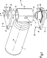
【図1】 一端に開口装置を配置したガス圧容器の斜視図である。
【図2】 図1の斜視図において、開口装置のハウジングを開口させて示した図である。
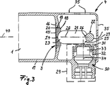
【図3】 爆薬装填部を備えた開口装置の第1実施形態の断面図である。
【図4】 熱電式作動装置を備えた開口装置の第2実施形態を示す図である。
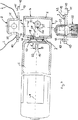
【図5】 電気式作動装置を備えた複動型開口装置を備えるガス圧容器の他の基本形状を示す図である。
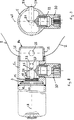
【図6】 爆薬装填部を有する作動装置を備えた、図5のガス圧容器を示す図である。
【図7】 絞りを備えたガス圧容器の部分断面図である。
【図8】 膨らませ穴とは反対側に端面キャップを備えたガス圧容器を半径方向に切断した断面図である。[0001]
The present invention is an opening device for a gas pressure vessel, which is connected to a discharge hole of the gas pressure vessel and is fixedly coupled to the gas pressure vessel, an internal space of the housing, and an internal space of the gas pressure vessel The internal space of the housing is sealed against the internal space of the gas pressure vessel by closing the exhaust hole of the gas pressure vessel, and sealed by the gas pressure in the gas pressure vessel It said sealing element being supported by the opposite support member via the pressure member to resist opening forces acting on the element, and a working device are supported separately and the sealing element, actuating device by eliminating the support of the sealing element during operation, to said opening device you so that inflation of the air bag drainage hole is opened by the gas pressure in the gas container.
[0002]
An opening device of this kind is known from German Offenlegungsschrift 19540618. The exhaust hole of the gas pressure vessel is closed by a sealing element, and the sealing element is supported by a counter support member fixed to the housing via a pressurizing member to support the gas force. The pressure member is provided with an explosive loading portion, and when the explosive loading portion is ignited, the opposing support member is damaged and the support of the sealing element is canceled. At this time, the sealing element is broken only by the gas pressure in the gas pressure vessel, and the airbag connected to the housing is inflated by the outflowing gas.
[0003]
From German Patent No. 197227047 it is known to fill a gas pressure accumulator with an inert gas, for example with at least one gas consisting of a group of nitrogen, argon and helium. The filled gas pressure vessel is closed by a rupture disc. The rupture disc is welded to the gas pressure vessel and is opened by the explosion pressure in the explosive loading section .
[0004]
The gas pressure container to be filled is manufactured by a subcontractor and shipped to a customer. Gas pressure vessels that are ready for shipping include opening devices that are each ready for operation, each with an explosive loading section . Therefore, careful operation is required during manufacture, shipping, and final assembly to avoid inadvertent operation of the opening device.
[0005]
Furthermore, it has been confirmed that the gas accumulated in the gas pressure vessel must be in a specific mixed state in order to inflate quickly and properly without mechanically damaging the airbag.
[0006]
The object of the present invention is to avoid inadvertent operation of the opening device during manufacturing, shipping and final assembly in this type of opening device.
[0007]
According to the present invention, according to the present invention, the housings that are open on opposite sides have a main body that is coupled to the gas pressure vessel, and the open end surface of the main body is closed by an end face plate that is provided separately from the main body. This is possible and is solved by the fact that the actuating device is held on one end plate as a unit which can be mounted independently and independently of the housing.
[0008]
According to the invention, the actuating device is implemented as a unit that can be mounted independently of the housing. Since the support of the sealing element is stable independently of the actuating device, the opening device can be preinstalled with the gas pressure vessel without the actuating device. Since the housing remains open on the opposite side, even if the sealing element is inadvertently opened, the pressurized gas will flow out from the opposite side of the same opening area, so that only a reaction force with no thrust force is present. Occur. Therefore, since the gas pressure vessel hardly moves or does not move at all, when it is attached and shipped in advance and finally assembled, high stability can be obtained without additional cost. The actuating device is preinstalled separately from the opening device and the gas pressure vessel. Only when the final installation is made, the opening device for the gas pressure vessel is provided with an actuating device, so that the entire device is brought into operation ready. However, in this case, since the gas pressure vessel is fixedly attached, the thrust force generated in the exhaust gas is captured.
[0009]
The housing is advantageously formed from a body connected to the gas pressure vessel and having an open end. The open end face can be closed by an end face plate. In this case, the housing body can be closed with a temporary end plate for shipping. Both end plates have drain holes of the same size. In this way, damage to the opening device in the housing is reliably avoided. For the first time of assembly, the actuator attached to one end plate is mounted on the housing body. In this case, the end plate opposite to the actuator has a drain hole necessary for filling the airbag. Yes. The purpose is to fix the airbag to this end face plate.
[0010]
In order to ensure a precise mounting of the actuator, the opening edge of the end face of the housing body engages the receiving groove of the end face plate.
Other features of the invention will be apparent from the other claims, the following description and the drawings. In the drawings, several embodiments of the invention are illustrated.
[0011]
The gas pressure vessel 1 illustrated in FIG. 1 is used for inflating an
As can be seen from FIGS. 2 and 3, a
[0012]
The
[0013]
The gas pressure vessel 1 opens substantially at the center of the
[0014]
The
[0015]
The sealing
[0016]
Since the
[0017]
The
[0018]
The
[0019]
As can be seen from FIG. 3, the sealing
[0020]
In the embodiment of FIG. 4, instead of the
[0021]
The embodiment of FIG. 5 corresponds in principle to the
[0022]
Since the embodiment of FIG. 6 corresponds in principle to the embodiment of FIG. 5, the same reference numerals are used for the same members.
Both the
[0023]
Since the embodiment of FIG. 7 corresponds to the embodiment of FIG. 2 in terms of configuration, the same reference numerals are used for the same members. The
[0024]
The opening cross section of the
[0025]
The gas pressure vessel is advantageously filled with a helium mixture, in particular mainly helium or other suitable noble gas. The rare gas has a low temperature dependency and has a high inflation (inflation) speed when the accumulated pressure is the same, which is advantageous because the airbag can be inflated in a very short time.
[0026]
In order to reliably prevent mechanical damage to the airbag, a throttle is provided in the gas pressure vessel 1 in front of the
[0027]
Since the squeezing
[0028]
The purpose is to provide a bowl-shaped recess in the
In the embodiment illustrated in FIGS. 8 and 9, the bottle neck includes a
[Brief description of the drawings]
FIG. 1 is a perspective view of a gas pressure vessel having an opening device at one end.
FIG. 2 is a view showing an opening device housing opened in the perspective view of FIG. 1;
FIG. 3 is a cross-sectional view of a first embodiment of an opening device with an explosive loading section .
FIG. 4 is a view showing a second embodiment of an opening device provided with a thermoelectric operating device.
FIG. 5 is a view showing another basic shape of a gas pressure vessel provided with a double-acting opening device provided with an electric actuator.
6 shows the gas pressure vessel of FIG. 5 with an actuating device having an explosive loading section .
FIG. 7 is a partial cross-sectional view of a gas pressure vessel provided with a throttle.
FIG. 8 is a cross-sectional view of a gas pressure vessel provided with an end cap on the side opposite to the inflating hole, cut in the radial direction.
Claims (9)
互いに対向する側(6,7)において開口しているハウジング(4)が、ガス圧容器(1)と結合される本体(5)を有し、本体(5)の開口端面(6,7)が本体(5)とは別個に設けられる端面板(8,9)により閉鎖可能であり、作動装置(30)が、ハウジング(4)とは別個に独立して取り付け可能なユニット(29)として一方の端面板(9)で保持されていることを特徴とする開口装置。An opening device for a gas pressure vessel, which is connected to a discharge hole (3) of the gas pressure vessel (1) and is fixedly coupled to the gas pressure vessel (1), and a housing (4 ) And the internal space of the gas pressure vessel (1), and by closing the exhaust hole (3) of the gas pressure vessel (1), the internal space of the housing (4) is The sealing element (15) sealed against the internal space of (1) is pressurized so as to resist the opening force acting on the sealing element (15) by the gas pressure in the gas pressure vessel (1). includes a member (21) said sealing element is supported by the opposite support member (22) through (15), the actuating device is supported separately from the sealing element (15) and (30), the actuator ( 30) releases the support of the sealing element (15) when activated, so that the drainage hole (3) In the opening apparatus in so that inflation of the air bag (2) is open by means of the gas pressure in the scan vessel (1),
The housing (4) opened on the opposite sides (6, 7) has a main body (5) coupled to the gas pressure vessel (1), and the open end face (6, 7) of the main body (5). Can be closed by end plates (8, 9) provided separately from the main body (5) , and the actuating device (30) can be installed as a unit (29) that can be attached independently from the housing (4) An opening device characterized by being held by one end face plate (9).
Applications Claiming Priority (3)
| Application Number | Priority Date | Filing Date | Title |
|---|---|---|---|
| DE19739375A DE19739375B4 (en) | 1997-09-09 | 1997-09-09 | Opening device for a gas pressure tank of an airbag |
| DE19739375.6 | 1997-09-09 | ||
| PCT/EP1998/005755 WO1999012775A1 (en) | 1997-09-09 | 1998-09-09 | Opening device for the gas pressure container of an airbag |
Publications (2)
| Publication Number | Publication Date |
|---|---|
| JP2001515816A JP2001515816A (en) | 2001-09-25 |
| JP3665740B2 true JP3665740B2 (en) | 2005-06-29 |
Family
ID=7841654
Family Applications (1)
| Application Number | Title | Priority Date | Filing Date |
|---|---|---|---|
| JP2000510621A Expired - Fee Related JP3665740B2 (en) | 1997-09-09 | 1998-09-09 | Opening device for gas pressure vessel of airbag |
Country Status (8)
| Country | Link |
|---|---|
| US (1) | US6247725B1 (en) |
| EP (1) | EP1012006B1 (en) |
| JP (1) | JP3665740B2 (en) |
| AT (1) | ATE324299T1 (en) |
| DE (2) | DE19739375B4 (en) |
| ES (1) | ES2263219T3 (en) |
| PT (1) | PT1012006E (en) |
| WO (1) | WO1999012775A1 (en) |
Families Citing this family (49)
| Publication number | Priority date | Publication date | Assignee | Title |
|---|---|---|---|---|
| DE10031750A1 (en) * | 2000-06-29 | 2002-01-10 | Welz Industrieprodukte Gmbh | Cold gas generator for an airbag system |
| US20030137135A1 (en) * | 2000-06-29 | 2003-07-24 | Welz Industrieprodukte Gmbh | Cold Gas Generator |
| DE10031749A1 (en) * | 2000-06-29 | 2002-01-10 | Welz Industrieprodukte Gmbh | Cold gas generator |
| DE10031751A1 (en) * | 2000-06-29 | 2002-01-10 | Welz Industrieprodukte Gmbh | Cold gas generator |
| FR2811624B1 (en) * | 2000-07-12 | 2002-12-06 | Alstom | EXHAUST DEVICE FOR AN INFLATABLE ELEMENT AND DEVICE FOR PROTECTING A VEHICLE AGAINST IMPACT EQUIPPED WITH SUCH AN EXHAUST DEVICE |
| DE20016041U1 (en) | 2000-09-15 | 2002-02-21 | Breed Automotive Technology, Inc., Lakeland, Fla. | Device for driving a piston for releasing a filling gas from a gas generator, in particular gas storage |
| JP2002172995A (en) * | 2000-09-28 | 2002-06-18 | Takata Corp | Storage gas inflator |
| DE10063093B4 (en) * | 2000-12-18 | 2005-10-13 | Key Safety Systems, Inc., Sterling Heights | Device for filling an airbag |
| DE10103974B4 (en) * | 2001-01-30 | 2006-03-09 | Key Safety Systems, Inc., Sterling Heights | Device for testing the filling pressure of an airbag gas storage |
| JP4864251B2 (en) * | 2001-02-26 | 2012-02-01 | 株式会社ダイセル | Inflator |
| DE10112558B4 (en) * | 2001-03-15 | 2006-04-20 | Key Safety Systems, Inc., Sterling Heights | Device for filling an airbag |
| DE20104433U1 (en) | 2001-03-15 | 2001-06-13 | Breed Automotive Technology, Inc., Lakeland, Fla. | Device for inflating an airbag |
| GB2373310B (en) * | 2001-03-15 | 2005-02-02 | Autoliv Dev | Improvements in or relating to an inflator |
| US6914742B1 (en) | 2001-06-22 | 2005-07-05 | Seagate Technology Llc | Data storage assembly with robust servo writing methodology |
| US7332330B2 (en) * | 2001-09-11 | 2008-02-19 | Renamed Biologics, Inc. | Device for maintaining vascularization near an implant |
| US6554315B2 (en) * | 2001-09-27 | 2003-04-29 | Trw Inc. | Inflatable vehicle occupant protection device |
| DE10297387T5 (en) | 2001-10-30 | 2005-02-24 | Seagate Technology Llc, Scotts Valley | A low density gas disk drive servo track recorder |
| DE10158222B4 (en) * | 2001-11-16 | 2013-07-18 | TAKATA Aktiengesellschaft | Tripping device for safety system |
| JP4063039B2 (en) * | 2001-12-10 | 2008-03-19 | タカタ株式会社 | Inflator assembly and air belt |
| US6629703B2 (en) | 2001-12-14 | 2003-10-07 | Breed Automotive Technology, Inc. | Opening device for a cold gas inflator |
| DE10202552B4 (en) * | 2002-01-24 | 2016-04-21 | Volkswagen Ag | Valve arrangement for a pressure vessel of an airbag inflator |
| DE60207448T2 (en) * | 2002-04-10 | 2006-07-27 | Dalphi-Metal España S.A. | PRESSURE GAS TANK |
| US6726243B2 (en) * | 2002-05-31 | 2004-04-27 | Autoliv Asp, Inc. | Tuning the performance of compressed gas-containing inflators |
| US6908105B2 (en) * | 2002-06-26 | 2005-06-21 | Daicel Chemical Industries, Ltd. | Gas generator for air bag |
| US7175198B2 (en) | 2002-08-20 | 2007-02-13 | Daicel Chemical Industries, Ltd. | Inflator |
| JP2004074947A (en) * | 2002-08-20 | 2004-03-11 | Daicel Chem Ind Ltd | Inflater |
| US7293797B2 (en) * | 2002-10-07 | 2007-11-13 | Daicel Chemical Industries, Ltd. | Inflator |
| JP4067929B2 (en) * | 2002-10-07 | 2008-03-26 | ダイセル化学工業株式会社 | Inflator |
| JP4628106B2 (en) * | 2002-11-14 | 2011-02-09 | オートモーティブ システムズ ラボラトリー インコーポレーテッド | Pressurized gas release mechanism |
| AT6624U1 (en) * | 2002-11-29 | 2004-01-26 | Isi Airbag Gmbh | KALTGAS GENERATOR |
| US6857657B2 (en) | 2003-04-07 | 2005-02-22 | Key Safety Systems, Inc. | Inflator having a support member capable of sliding to open the pressure vessel |
| DE10318888B3 (en) * | 2003-04-17 | 2004-10-28 | Takata-Petri (Ulm) Gmbh | Gas generator for a vehicle occupant-protection system comprises rupturing devices supported on each other when a compressed gas store is closed and designed so that they only together withstand the pressure of the compressed gas store |
| DE20306818U1 (en) * | 2003-05-02 | 2003-09-11 | TRW Occupant Restraint Systems GmbH & Co. KG, 73553 Alfdorf | The gas bag module |
| DE10333895A1 (en) * | 2003-07-22 | 2005-02-17 | Petri-Dn Gmbh Inflator Systems | Gas generator for filling airbag of motor vehicle, comprises a counter bearing which has a base body and a support plate which is formed by a separate part |
| DE10346372A1 (en) * | 2003-09-29 | 2005-05-25 | Petri-Dn Gmbh Inflator Systems | Automotive air bag module has a gas bag root inflation assembly guiding inflation gases along cage sidewalls |
| DE102004026436A1 (en) * | 2004-05-27 | 2005-12-22 | Werner Herrmann | Non-pyrotechnic safety and actuating device for e.g. airbag includes crash sensor, actuator bolt, magnetic coil, support element, retaining element, guide element and propellent gas container |
| US7316417B2 (en) * | 2004-06-30 | 2008-01-08 | Autoliv Asp, Inc. | Inflator with internally mounted initiator |
| GB2417066B (en) * | 2004-08-13 | 2006-12-06 | Autoliv Dev | Improvements in or relating to an inflator for an air-bag |
| DE602005010730D1 (en) | 2005-12-20 | 2008-12-11 | Key Safety Systems Inc | Gas generator with throttle for variable gas flow |
| DE602005010729D1 (en) | 2005-12-20 | 2008-12-11 | Key Safety Systems Inc | Gas generator with improved cap |
| JP2008201244A (en) * | 2007-02-20 | 2008-09-04 | Daicel Chem Ind Ltd | Inflator for occupant restraining system for vehicle |
| US7914040B1 (en) * | 2007-04-27 | 2011-03-29 | Tk Holdings, Inc. | Cold gas generating system |
| US7658406B2 (en) * | 2007-07-22 | 2010-02-09 | Key Safety Systems, Inc. | Venting device for an airbag inflator |
| CN101918251B (en) * | 2008-01-15 | 2012-11-07 | 奥托立夫开发公司 | An inflator for an air-bag |
| US8113542B1 (en) * | 2008-01-22 | 2012-02-14 | Tk Holdings, Inc. | Pressurized gas release mechanism |
| US8235417B2 (en) * | 2009-06-15 | 2012-08-07 | Nxgen Technologies, Llc | Apparatus and method for releasing an inflation gas from an inflator |
| EP2527210B1 (en) * | 2011-05-25 | 2013-12-25 | Autoliv Development AB | An inflator for an air bag |
| DE102011080342A1 (en) * | 2011-08-03 | 2013-02-07 | Robert Bosch Gmbh | Cold gas generator for providing cold gas for activation of an impact bag and method for providing cold gas for an impact bag activation |
| IT201700109554A1 (en) | 2017-09-29 | 2019-03-29 | Getters Spa | Air bag module |
Family Cites Families (15)
| Publication number | Priority date | Publication date | Assignee | Title |
|---|---|---|---|---|
| JPS4716499Y1 (en) * | 1970-04-25 | 1972-06-09 | ||
| JPS497958Y1 (en) * | 1970-04-30 | 1974-02-25 | ||
| US3663036A (en) * | 1970-06-16 | 1972-05-16 | Olin Corp | Vehicle safety device having an inflatable confinement |
| US3837671A (en) * | 1972-11-06 | 1974-09-24 | Allied Chem | Inflating means for inflatable vehicle restraint systems |
| JPS5398637A (en) * | 1977-02-08 | 1978-08-29 | Honda Motor Co Ltd | Composite link device |
| US4275901A (en) * | 1978-07-21 | 1981-06-30 | Honda Giken Kogyo Kabushiki Kaisha | Inflatable safety bag system for vehicles |
| JPS63103749A (en) * | 1986-10-22 | 1988-05-09 | Koichi Kaneda | Shock detecting operation mechanism for air bag device |
| US5236675A (en) * | 1992-04-08 | 1993-08-17 | Daicel Chemical Industries, Ltd. | Gas generator with circumferential joints |
| CA2156362C (en) * | 1994-09-12 | 1998-06-30 | Jess A. Cuevas | Mini inflator assembly |
| DE19540618A1 (en) * | 1995-10-31 | 1997-05-07 | Autoliv Dev | Device for flowing pressurized gas into a vehicle safety device |
| DE19540619A1 (en) * | 1995-10-31 | 1997-05-07 | Autoliv Dev | Gas-filled pressure tank for vehicle safety arrangement |
| GB2309511A (en) * | 1996-01-25 | 1997-07-30 | Grew W W & Co Ltd | Inflation of airbags and other inflatable articles |
| US5820162A (en) * | 1996-03-21 | 1998-10-13 | Airbelt Systems, Llc. | Airbag system inflator |
| JPH1071922A (en) | 1996-06-26 | 1998-03-17 | Nissan Motor Co Ltd | Gas generator |
| DE29714433U1 (en) * | 1997-08-12 | 1997-10-09 | Autoflator Ab, Vargarda | Airbag inflating device |
-
1997
- 1997-09-09 DE DE19739375A patent/DE19739375B4/en not_active Expired - Fee Related
-
1998
- 1998-09-09 WO PCT/EP1998/005755 patent/WO1999012775A1/en active IP Right Grant
- 1998-09-09 US US09/508,500 patent/US6247725B1/en not_active Expired - Fee Related
- 1998-09-09 DE DE59813520T patent/DE59813520D1/en not_active Expired - Lifetime
- 1998-09-09 ES ES98948949T patent/ES2263219T3/en not_active Expired - Lifetime
- 1998-09-09 AT AT98948949T patent/ATE324299T1/en not_active IP Right Cessation
- 1998-09-09 EP EP19980948949 patent/EP1012006B1/en not_active Expired - Lifetime
- 1998-09-09 PT PT98948949T patent/PT1012006E/en unknown
- 1998-09-09 JP JP2000510621A patent/JP3665740B2/en not_active Expired - Fee Related
Also Published As
| Publication number | Publication date |
|---|---|
| EP1012006A1 (en) | 2000-06-28 |
| JP2001515816A (en) | 2001-09-25 |
| DE59813520D1 (en) | 2006-06-01 |
| DE19739375A1 (en) | 1999-03-18 |
| ES2263219T3 (en) | 2006-12-01 |
| WO1999012775A1 (en) | 1999-03-18 |
| DE19739375B4 (en) | 2005-07-28 |
| US6247725B1 (en) | 2001-06-19 |
| EP1012006B1 (en) | 2006-04-26 |
| ATE324299T1 (en) | 2006-05-15 |
| PT1012006E (en) | 2006-06-30 |
Similar Documents
| Publication | Publication Date | Title |
|---|---|---|
| JP3665740B2 (en) | Opening device for gas pressure vessel of airbag | |
| EP0652141B1 (en) | Isolation member for air bag inflator | |
| US6206420B1 (en) | Device for introducing pressurized gas into a vehicle safety device | |
| US6908106B2 (en) | Inflator | |
| EP0949126B1 (en) | Airbag inflator | |
| US6612326B2 (en) | Inflator | |
| JPH0829695B2 (en) | Protective equipment for passengers of automobiles | |
| US7679019B2 (en) | Electrical switching system | |
| US5513572A (en) | Hybrid inflator | |
| US5727812A (en) | Airbag cushion assembly having a horn switch secured with a cushion strap | |
| WO2015060081A1 (en) | Rupture disk and inflator using same | |
| US11498514B2 (en) | Overigniting protection device, second ignition stage, gas generator and airbag module | |
| JP4672115B2 (en) | Expansion device for automotive safety equipment | |
| US5873596A (en) | Air bag device having horn switch | |
| US9789845B2 (en) | Combustion chamber comprising an opening device for a compressed gas tank of a hybrid inflator, hybrid inflator, airbag module, vehicle safety system and method of discharging fluid from an inflator | |
| EP3166822B1 (en) | Igniter assembly with retractable piston | |
| JP2004501822A (en) | Cold gas generator | |
| US3951428A (en) | Gas bag inflating device | |
| JP4576282B2 (en) | Gas generator for airbag | |
| CA2216917C (en) | Gas generating apparatus for air bag apparatus | |
| JP6054232B2 (en) | Gas generator | |
| JP4067929B2 (en) | Inflator | |
| CA2191791A1 (en) | Apparatus for inflating an airbag | |
| EP2365921A1 (en) | Inflator with means for increasing the output flow of pressurized gas | |
| KR200260255Y1 (en) | opening and shutting device for pressed gas |
Legal Events
| Date | Code | Title | Description |
|---|---|---|---|
| A131 | Notification of reasons for refusal |
Free format text: JAPANESE INTERMEDIATE CODE: A131 Effective date: 20040629 |
|
| A601 | Written request for extension of time |
Free format text: JAPANESE INTERMEDIATE CODE: A601 Effective date: 20040928 |
|
| A602 | Written permission of extension of time |
Free format text: JAPANESE INTERMEDIATE CODE: A602 Effective date: 20041005 |
|
| A521 | Request for written amendment filed |
Free format text: JAPANESE INTERMEDIATE CODE: A523 Effective date: 20041224 |
|
| TRDD | Decision of grant or rejection written | ||
| A01 | Written decision to grant a patent or to grant a registration (utility model) |
Free format text: JAPANESE INTERMEDIATE CODE: A01 Effective date: 20050308 |
|
| A61 | First payment of annual fees (during grant procedure) |
Free format text: JAPANESE INTERMEDIATE CODE: A61 Effective date: 20050404 |
|
| R150 | Certificate of patent or registration of utility model |
Free format text: JAPANESE INTERMEDIATE CODE: R150 |
|
| FPAY | Renewal fee payment (event date is renewal date of database) |
Free format text: PAYMENT UNTIL: 20090408 Year of fee payment: 4 |
|
| FPAY | Renewal fee payment (event date is renewal date of database) |
Free format text: PAYMENT UNTIL: 20090408 Year of fee payment: 4 |
|
| FPAY | Renewal fee payment (event date is renewal date of database) |
Free format text: PAYMENT UNTIL: 20100408 Year of fee payment: 5 |
|
| FPAY | Renewal fee payment (event date is renewal date of database) |
Free format text: PAYMENT UNTIL: 20110408 Year of fee payment: 6 |
|
| FPAY | Renewal fee payment (event date is renewal date of database) |
Free format text: PAYMENT UNTIL: 20120408 Year of fee payment: 7 |
|
| LAPS | Cancellation because of no payment of annual fees |