JP3665592B2 - Mat washing machine - Google Patents
Mat washing machine Download PDFInfo
- Publication number
- JP3665592B2 JP3665592B2 JP2001256587A JP2001256587A JP3665592B2 JP 3665592 B2 JP3665592 B2 JP 3665592B2 JP 2001256587 A JP2001256587 A JP 2001256587A JP 2001256587 A JP2001256587 A JP 2001256587A JP 3665592 B2 JP3665592 B2 JP 3665592B2
- Authority
- JP
- Japan
- Prior art keywords
- mat
- outer cylinder
- inner cylinder
- washing machine
- cylinder
- Prior art date
- Legal status (The legal status is an assumption and is not a legal conclusion. Google has not performed a legal analysis and makes no representation as to the accuracy of the status listed.)
- Expired - Fee Related
Links
Images

Classifications
-
- D—TEXTILES; PAPER
- D06—TREATMENT OF TEXTILES OR THE LIKE; LAUNDERING; FLEXIBLE MATERIALS NOT OTHERWISE PROVIDED FOR
- D06G—MECHANICAL OR PRESSURE CLEANING OF CARPETS, RUGS, SACKS, HIDES, OR OTHER SKIN OR TEXTILE ARTICLES OR FABRICS; TURNING INSIDE-OUT FLEXIBLE TUBULAR OR OTHER HOLLOW ARTICLES
- D06G1/00—Beating, brushing, or otherwise mechanically cleaning or pressure cleaning carpets, rugs, sacks, hides, or other skin or textile articles or fabrics
- D06G1/005—Beating, brushing, or otherwise mechanically cleaning or pressure cleaning carpets, rugs, sacks, hides, or other skin or textile articles or fabrics inside a rotary receptacle
Description
【0001】
【発明の属する技術分野】
この発明は、回転ドラム式の洗濯機に関するもので、特に寝台のマットを洗浄するのに適した回転ドラム式洗濯機に関するものである。
【0002】
【従来の技術】
洗濯物を収容し、洗濯液に一部浸漬された状態で回転する回転ドラムを備えた回転ドラム式洗濯機は、業務用洗濯機として広く用いられており、衣類を痛めないで効率よく洗濯できるという特徴を備えている。洗濯物を収容する回転ドラムは、水平軸回りに回転する構造が一般的で、洗濯終了後回転ドラムを高速回転させて脱水を行い、更には低速回転する回転ドラム内に温風を通過させて、脱水後の乾燥まで行うものも用いられている。
【0003】
このような回転ドラム式洗濯機で寝台のマットや和布団などのような大型の洗濯物を洗濯しようとすると、洗濯物が偏在したときに回転ドラムのアンバランスが非常に大きくなって、洗濯機の円滑な運転が妨げられる。そこで、マットや和布団を回転ドラムの周面に定置させて、回転ドラムのアンバランスが生じないようにする技術が特開平6−114181号公報や、特開2000−135396号公報により提案されている。
【0004】
特開平6−114181号公報に記載の発明は、本願出願人の出願に係るもので、曲げ方向や長さ方向にも弾力性を備えたマットの洗濯に適したもので、回転ドラムの内周面に所定間隔でドラムの軸方向の畝状突起を設け、隣接する畝状突起の間にマットを少し弾性圧縮した状態で嵌め込むことにより、マットを回転ドラムの周面に定置させるようにしたものである。
【0005】
一方、特開2000−135396号公報に開示された発明は、柔軟な和布団の洗濯に適したもので、同心に配置されて一体に回転する外筒と内筒とを備え、和布団を内筒に巻き付けた状態で内筒と外筒との間に収容することにより、和布団を回転ドラム内に定置させるようにしたものである。
【0006】
【発明が解決しようとする課題】
特開平6−114181号公報記載のものは、複数枚のマットを同時に洗濯するような大型のマット洗濯機の構造として特に適しており、回転ドラムへのマットの挿入も容易である。それは、回転ドラムが大型であれば、畝状突起間にマットを収納するときのマットの屈曲量も比較的小さいため、回転ドラムへのマットの嵌め込み作業が比較的容易にできることによる。これに対してマットを1枚ずつ洗濯するような小型の洗濯機のときは、マットを回転ドラムに挿入するときに、マットをほとんど360度近くまで屈曲してやる必要があるが、このときマットが円弧状にならないでU字状やV字状に屈折するため、マットを回転ドラムに嵌め込む際に、より多くの熟練と腕力とが必要である。
【0007】
小型のマット洗濯機は、病院に設置されることも多く、その場合には洗濯機へのマットの出し入れが女性の手で行われることが多いので、マットの装脱に腕力を要しないことが要求される。
【0008】
一方、特開2000−135396号記載のものは、和布団を内筒に巻き付けて収容することからも理解されるように、小型の洗濯機に適した構造である。内筒と外筒とを同心に配置した構造は、柔軟でかつ濡れたときに非常に重くなる和布団をバランス良く回転ドラム内に保持するのに有効である。しかし曲げ方向にも弾力性を有するマットの場合には、内筒に丸く巻き付けようとしても、マットはU字ないしV字状に折れ曲がろうとし、弾力で真っ直ぐになろうとするマットの両端部分を円弧状に曲げて内筒と外筒との間に挿入するのに腕力や熟練が必要になるという前記特開平6−114181号公報記載のものと同様な問題が生ずる。
【0009】
そこでこの発明は、病院の寝台等に用いられている曲げ方向にも弾力性を備えたマットの洗浄に適した小型の洗濯機を得ることを課題としており、非力な女性でも容易に回転ドラム内へのマットの挿入を行うことができ、かつ洗濯中におけるマットの移動や回転ドラムのアンバランスを生じない回転ドラム式マット洗濯機を得ることを課題としている。
【0010】
【課題を解決するための手段】
この発明のマット洗濯機の回転ドラム3は、外筒7と内筒8との二重円筒構造を備えており、かつ内筒8は外筒7の中心に対して偏心している。ドラムの回転は外筒7の軸心回りに行われる。内筒8が外筒7に偏心している関係上、内筒8と外筒7との間の径方向の間隙は、偏心側14で狭く、反偏心側で広い。狭い方の偏心側の間隙14は、洗濯しようとするマットの厚さより必要な遊隙分だけ広い。
【0011】
内筒8を偏心させたことによるアンバランス及び回転ドラム内へのマットの装着状態に起因するアンバランスをバランスさせるために、内筒8の偏心方向と反対の方向の適宜な箇所にバランス部材15を一般的には外筒7に固定して設ける。
【0012】
洗濯しようとするマット17は、長さ中央部を内筒8と外筒7の間隔が最も狭くなった部分に差込まれるようにして、内筒8と外筒7との間に挿入する。このようにマットを挿入すると、真っ直ぐな状態を保とうとするマットの両端付近は、内筒8と外筒7との間の間隔が広くなった反偏心側の間隙の部分に差し込まれるため、マットの端部を無理やり曲げる必要がなくなり、回転ドラムへのマットの挿入が容易になる。
【0013】
回転ドラムの外筒7の内周面には、挿入したマットの周方向の移動を防止するためのストッパを設けておくのが好ましく、このストッパは内筒の反偏心側の外筒内面に固定されることとなるので、このストッパをバランス部材とすることが可能である。すなわち、内筒8を偏心させたことによるアンバランスを解消するのに必要なバランス部材の重量と、ストッパの装着位置とから算出される重量をストッパ15に付与してボルトなどにより外筒7の内周面に固定する。
【0014】
このストッパ15は挿入されたマットの端部から若干離れた位置に固定するようにしてもよく、これによりストッパ15の位置を変更することなく、若干であれば長さの違うマットを洗濯することができる。
【0015】
【発明の実施の形態】
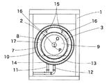
図1及び図2は、この発明のマット洗濯機の一実施例を示した図である。フレーム1には液封構造の洗濯槽10が固定され、回転軸2が水平に軸支されている。この回転軸の一端は、洗濯槽10の後壁を貫通してその先端に回転ドラム3が固定されている。回転軸2の他端にはプーリ4が固定され、ベルト5を介してフレーム1に搭載した電動機6で回転駆動される。洗濯槽10及び回転ドラム3は反回転軸側の端面が開放されて洗濯物の投入排出口となっている。
【0016】
回転ドラム3は、ステンレスの穴明き板からなる外筒7と内筒8とを備えている。外筒7の軸心Oは、回転軸2の軸心と一致しており、内筒8の軸心Pは、回転軸2の中心すなわち外筒7の軸心Oに対して偏心している。外筒7は、回転軸2に固定された支持円板9に溶着されており、内筒8はその奥端において支持円板9に図示しないボルトで固定されている。
【0017】
洗濯槽10にはそれぞれ電磁バルブを備えた洗濯液供給管11と、洗濯液排出管12とが接続されており、所定のレベルまで洗濯液13が供給されて回転ドラム3はその下方部分が洗濯液13に浸漬した状態で回転する。この洗濯機で洗濯後のマットの脱水も行うときは、洗濯液排出管12から洗濯液を排出した後、回転ドラム3を高速回転させる。
【0018】
図1、2は内筒8の偏心方向を下方にした状態で回転ドラムを図示している。従って図1においては、図の下端側で内筒8と外筒7との間の間隙14が最も狭く、上方では広くなっている。内筒8の反偏心側、すなわち図1の回転ドラムの上方部分に2本のストッパ15が外筒7の内周面にボルトで固定して取付けられている。このストッパ15は、断面が略V字状の回転ドラムの軸方向に長い部材で、そのマット側を向く面16が外筒7の内面と直交する角度になるようにして外筒7に固定されている。
【0019】
この2本のストッパ15は、内筒8の偏心方向とちょうど反対の方向、すなわち図1の外筒の真上の位置に対して対称に配置されている。内筒8を回転軸2の中心から偏心させたことによるアンバランスは、その偏心方向と反対の方向に2本のストッパ15を固定することによりバランスさせている。同時にこのストッパ15は、内筒8と外筒7との間に挿入されたマット17の周方向の移動を阻止する機能を有している。
【0020】
マット17は図1に想像線で示すように、略円弧状に屈曲して内筒8と外筒7との間の間隙に挿入される。内筒8と外筒7との間の間隔が最も狭くなった位置14にマット17の長手中間部が挿入される。従ってマットの両端部は、内筒8と外筒7との間隔が広くなった位置に挿入されることとなり、マットの厚さに対して十分に余裕のある間隙となっているため、マットの端部を無理に曲げなくても挿入することができる。
【0021】
挿入されたマットは真っ直ぐになろうとする弾力が内筒8と外筒7とによって抑制されて、回転ドラム3の周面に沿った状態で保持され、かつストッパ15により周方向の大きな移動が防止される。
【0022】
なお、洗濯槽10には回転ドラムの開口を閉鎖するように扉18が設けられており、この扉18を開いてマット17の出し入れを行い、扉を閉じて洗濯槽10を密閉した状態で洗濯や脱水操作が行われる。
【0023】
また、図示実施例のものでは、内筒8及びストッパ15をボルト止めしているので、これを取外して外筒内面に適宜ビータを取付けることにより、通常の衣類の洗濯機として用いることができ、また通常の衣類の洗濯機のビータを取り外して、内筒8とストッパ15とを取付けることにより、この発明のマット洗濯機とすることが可能である。
【0024】
【発明の効果】
以上説明したこの発明によれば、曲げ方向の弾性を備えたマットをアンバランスを生じさせないで洗濯することができ、かつ洗濯機へのマットの挿入が容易で作業性のよい小型のマット洗濯機を提供できるという効果がある。
【図面の簡単な説明】
【図1】本発明の回転ドラム式マット洗濯機の回転ドラムを示すの正面図
【図2】本発明の回転ドラム式マット洗濯機の断面側面図
【符号の説明】
7 外筒
8 内筒
15 ストッパ
O 外筒の軸心
P 内筒の軸心[0001]
BACKGROUND OF THE INVENTION
The present invention relates to a rotary drum type washing machine, and more particularly to a rotary drum type washing machine suitable for cleaning a mat of a bed.
[0002]
[Prior art]
Rotating drum type washing machines equipped with rotating drums that store laundry and rotate while being partially immersed in the washing liquid are widely used as commercial washing machines and can wash clothes efficiently without damaging clothes It has the characteristics. Rotating drums that store laundry generally have a structure that rotates around a horizontal axis. After washing, the rotating drum is rotated at a high speed for dehydration, and further, hot air is passed through the rotating drum that rotates at a low speed. In addition, what is performed until drying after dehydration is also used.
[0003]
When trying to wash large laundry items such as bed mats or Japanese futons with a rotating drum type washing machine, the unbalance of the rotating drum becomes very large when the laundry is unevenly distributed. Smooth operation is hindered. Therefore, Japanese Patent Laid-Open No. 6-114181 and Japanese Patent Laid-Open No. 2000-135396 have proposed a technique in which a mat or Japanese futon is placed on the peripheral surface of the rotating drum so that the rotating drum is not unbalanced. Yes.
[0004]
The invention described in Japanese Patent Laid-Open No. 6-114181 relates to the application of the applicant of the present application, and is suitable for washing a mat having elasticity in the bending direction and the length direction. A drum-shaped projection in the axial direction of the drum is provided on the surface at a predetermined interval, and the mat is placed on the peripheral surface of the rotating drum by fitting the mat between the adjacent cage-shaped projections in a slightly elastically compressed state. Is.
[0005]
On the other hand, the invention disclosed in Japanese Patent Application Laid-Open No. 2000-135396 is suitable for washing a flexible Japanese futon, and includes an outer cylinder and an inner cylinder that are arranged concentrically and rotate integrally. The Japanese futon is placed in the rotating drum by being accommodated between the inner cylinder and the outer cylinder in a state of being wound around the cylinder.
[0006]
[Problems to be solved by the invention]
The one described in JP-A-6-114181 is particularly suitable as the structure of a large-sized mat washing machine for washing a plurality of mats at the same time, and the mat can be easily inserted into the rotating drum. This is because if the rotating drum is large, the amount of bending of the mat when the mat is accommodated between the hook-shaped projections is relatively small, so that the mat can be fitted into the rotating drum relatively easily. On the other hand, in the case of a small washing machine in which mats are washed one by one, it is necessary to bend the mat almost to 360 degrees when inserting the mat into the rotating drum. Since it is refracted into a U-shape or V-shape without being arcuate, more skill and strength are required when the mat is fitted into the rotating drum.
[0007]
Small mat washing machines are often installed in hospitals, and in that case, mats are often put in and out of the washing machine by a woman's hand, so it may not require arm strength to put on and take off the mat. Required.
[0008]
On the other hand, the one described in Japanese Patent Application Laid-Open No. 2000-135396 has a structure suitable for a small washing machine, as can be understood from the fact that a Japanese futon is wrapped around an inner cylinder and accommodated. The structure in which the inner cylinder and the outer cylinder are concentrically arranged is effective for holding a Japanese futon which is flexible and very heavy when wet in the rotating drum in a well-balanced manner. However, in the case of a mat that is also elastic in the bending direction, both ends of the mat that try to bend in a U-shape or V-shape and to be straightened by elasticity even if it is wrapped around the inner cylinder. A problem similar to that described in Japanese Patent Laid-Open No. 6-114181 arises in that arm force and skill are required to bend the tube into an arc shape and insert it between the inner tube and the outer tube.
[0009]
Therefore, an object of the present invention is to obtain a small washing machine suitable for washing a mat having elasticity in a bending direction used for a hospital bed or the like. It is an object of the present invention to obtain a rotating drum mat washing machine that can insert a mat into a mat and does not cause movement of the mat or unbalance of the rotating drum during washing.
[0010]
[Means for Solving the Problems]
The
[0011]
In order to balance the unbalance caused by the eccentricity of the
[0012]
The
[0013]
It is preferable to provide a stopper for preventing the inserted mat from moving in the circumferential direction on the inner peripheral surface of the
[0014]
This
[0015]
DETAILED DESCRIPTION OF THE INVENTION
1 and 2 are diagrams showing an embodiment of a mat washing machine according to the present invention. A liquid-sealed
[0016]
The
[0017]
A washing
[0018]
1 and 2 illustrate the rotating drum with the eccentric direction of the
[0019]
The two
[0020]
As shown by an imaginary line in FIG. 1, the
[0021]
The inserted mat is restrained by the
[0022]
The
[0023]
Also, in the illustrated embodiment, the
[0024]
【The invention's effect】
According to the present invention described above, the mat having the elasticity in the bending direction can be washed without causing imbalance, and the mat can be easily inserted into the washing machine and has a good workability. There is an effect that can be provided.
[Brief description of the drawings]
FIG. 1 is a front view showing a rotating drum of a rotating drum mat washing machine of the present invention. FIG. 2 is a sectional side view of a rotating drum mat washing machine of the present invention.
7
15 Stopper O Outer cylinder axis P Inner cylinder axis
Claims (2)
Priority Applications (1)
| Application Number | Priority Date | Filing Date | Title |
|---|---|---|---|
| JP2001256587A JP3665592B2 (en) | 2001-08-27 | 2001-08-27 | Mat washing machine |
Applications Claiming Priority (1)
| Application Number | Priority Date | Filing Date | Title |
|---|---|---|---|
| JP2001256587A JP3665592B2 (en) | 2001-08-27 | 2001-08-27 | Mat washing machine |
Publications (2)
| Publication Number | Publication Date |
|---|---|
| JP2003062376A JP2003062376A (en) | 2003-03-04 |
| JP3665592B2 true JP3665592B2 (en) | 2005-06-29 |
Family
ID=19084382
Family Applications (1)
| Application Number | Title | Priority Date | Filing Date |
|---|---|---|---|
| JP2001256587A Expired - Fee Related JP3665592B2 (en) | 2001-08-27 | 2001-08-27 | Mat washing machine |
Country Status (1)
| Country | Link |
|---|---|
| JP (1) | JP3665592B2 (en) |
Families Citing this family (3)
| Publication number | Priority date | Publication date | Assignee | Title |
|---|---|---|---|---|
| EP2514864B1 (en) | 2010-03-15 | 2020-08-12 | LG Electronics Inc. | Laundry machine and method for controlling same |
| CN112553857B (en) * | 2020-12-24 | 2022-07-01 | 济宁翔宇毛绒玩具股份有限公司 | Plush toy adds salt stirring cleaning device |
| CN113235283B (en) * | 2021-03-29 | 2023-09-22 | 安徽万利达羽绒制品有限公司 | Supporting and hanging mechanism applied to down jacket cleaning line |
-
2001
- 2001-08-27 JP JP2001256587A patent/JP3665592B2/en not_active Expired - Fee Related
Also Published As
| Publication number | Publication date |
|---|---|
| JP2003062376A (en) | 2003-03-04 |
Similar Documents
| Publication | Publication Date | Title |
|---|---|---|
| US5107606A (en) | Drum type washing apparatus and method of processing the wash using said apparatus | |
| US7398662B2 (en) | Gasket and washing machine using the same | |
| CN103031694A (en) | Washing machine | |
| US20070130730A1 (en) | Hinge assembly for door of laundry device | |
| US20060000244A1 (en) | Drum washing machine | |
| EP1738009A1 (en) | Drum assembly in washing machine and method for fabricating the same | |
| KR101217118B1 (en) | Washing machine | |
| CA2748841C (en) | Laundry machine | |
| KR101065703B1 (en) | Washing machine | |
| KR100790630B1 (en) | Drum type washing machine | |
| CA2748840A1 (en) | Laundry machine with tub support | |
| RU2505634C2 (en) | Machine for laundry processing | |
| JP3665592B2 (en) | Mat washing machine | |
| EP2389472B1 (en) | Laundry machine | |
| US6622530B1 (en) | Suspension mechanism for connecting the moving tub assembly of the washing machines with horizontal axis to the fixed body | |
| US20110283743A1 (en) | Washing machine | |
| US20050178168A1 (en) | Gasket and drum-type washing machine having the same | |
| JP2738957B2 (en) | Drum type washing machine | |
| US20030115913A1 (en) | Washing machine with an improved water tub | |
| KR100424315B1 (en) | The tub a of drum-washer | |
| US11788226B2 (en) | Water recirculation insert for laundry appliance | |
| US20210054555A1 (en) | Drum-type washing apparatus | |
| KR100712280B1 (en) | Balance weight combine structure for a tub of a drum-type washing machine | |
| CN100532693C (en) | Drying pipeline of drum washing machine | |
| JP3163976B2 (en) | Fully automatic washing machine |
Legal Events
| Date | Code | Title | Description |
|---|---|---|---|
| TRDD | Decision of grant or rejection written | ||
| A01 | Written decision to grant a patent or to grant a registration (utility model) |
Free format text: JAPANESE INTERMEDIATE CODE: A01 Effective date: 20050301 |
|
| A61 | First payment of annual fees (during grant procedure) |
Free format text: JAPANESE INTERMEDIATE CODE: A61 Effective date: 20050401 |
|
| R150 | Certificate of patent or registration of utility model |
Ref document number: 3665592 Country of ref document: JP Free format text: JAPANESE INTERMEDIATE CODE: R150 Free format text: JAPANESE INTERMEDIATE CODE: R150 |
|
| FPAY | Renewal fee payment (event date is renewal date of database) |
Free format text: PAYMENT UNTIL: 20080408 Year of fee payment: 3 |
|
| FPAY | Renewal fee payment (event date is renewal date of database) |
Free format text: PAYMENT UNTIL: 20110408 Year of fee payment: 6 |
|
| R250 | Receipt of annual fees |
Free format text: JAPANESE INTERMEDIATE CODE: R250 |
|
| FPAY | Renewal fee payment (event date is renewal date of database) |
Free format text: PAYMENT UNTIL: 20110408 Year of fee payment: 6 |
|
| FPAY | Renewal fee payment (event date is renewal date of database) |
Free format text: PAYMENT UNTIL: 20140408 Year of fee payment: 9 |
|
| R250 | Receipt of annual fees |
Free format text: JAPANESE INTERMEDIATE CODE: R250 |
|
| R250 | Receipt of annual fees |
Free format text: JAPANESE INTERMEDIATE CODE: R250 |
|
| R250 | Receipt of annual fees |
Free format text: JAPANESE INTERMEDIATE CODE: R250 |
|
| R250 | Receipt of annual fees |
Free format text: JAPANESE INTERMEDIATE CODE: R250 |
|
| R250 | Receipt of annual fees |
Free format text: JAPANESE INTERMEDIATE CODE: R250 |
|
| S111 | Request for change of ownership or part of ownership |
Free format text: JAPANESE INTERMEDIATE CODE: R313111 |
|
| R350 | Written notification of registration of transfer |
Free format text: JAPANESE INTERMEDIATE CODE: R350 |
|
| R250 | Receipt of annual fees |
Free format text: JAPANESE INTERMEDIATE CODE: R250 |
|
| LAPS | Cancellation because of no payment of annual fees |