JP3665397B2 - Endoscope light source device - Google Patents
Endoscope light source device Download PDFInfo
- Publication number
- JP3665397B2 JP3665397B2 JP31513395A JP31513395A JP3665397B2 JP 3665397 B2 JP3665397 B2 JP 3665397B2 JP 31513395 A JP31513395 A JP 31513395A JP 31513395 A JP31513395 A JP 31513395A JP 3665397 B2 JP3665397 B2 JP 3665397B2
- Authority
- JP
- Japan
- Prior art keywords
- light
- stepping motor
- shielding
- light source
- endoscope
- Prior art date
- Legal status (The legal status is an assumption and is not a legal conclusion. Google has not performed a legal analysis and makes no representation as to the accuracy of the status listed.)
- Expired - Fee Related
Links
- 238000005286 illumination Methods 0.000 claims description 29
- 239000012530 fluid Substances 0.000 claims description 12
- 230000000903 blocking effect Effects 0.000 claims description 7
- 230000009471 action Effects 0.000 claims description 3
- 230000003139 buffering effect Effects 0.000 claims description 3
- 238000013016 damping Methods 0.000 claims 1
- 230000007246 mechanism Effects 0.000 description 13
- 239000000835 fiber Substances 0.000 description 8
- 230000008878 coupling Effects 0.000 description 6
- 238000010168 coupling process Methods 0.000 description 6
- 238000005859 coupling reaction Methods 0.000 description 6
- 230000008859 change Effects 0.000 description 5
- 238000003384 imaging method Methods 0.000 description 5
- 230000015654 memory Effects 0.000 description 3
- 230000000694 effects Effects 0.000 description 2
- 230000003287 optical effect Effects 0.000 description 2
- 238000010586 diagram Methods 0.000 description 1
- 230000004907 flux Effects 0.000 description 1
- 238000009499 grossing Methods 0.000 description 1
- 238000003780 insertion Methods 0.000 description 1
- 230000037431 insertion Effects 0.000 description 1
- 239000007788 liquid Substances 0.000 description 1
- 229910052724 xenon Inorganic materials 0.000 description 1
- FHNFHKCVQCLJFQ-UHFFFAOYSA-N xenon atom Chemical compound [Xe] FHNFHKCVQCLJFQ-UHFFFAOYSA-N 0.000 description 1
Images


Landscapes
- Endoscopes (AREA)
- Instruments For Viewing The Inside Of Hollow Bodies (AREA)
Description
【0001】
【発明の属する技術分野】
この発明は、内視鏡の照明用ライトガイドに照明光を供給するための内視鏡用光源装置に関する。
【0002】
【従来の技術】
内視鏡用光源装置には、一般に、光源ランプから放射された照明光を内視鏡の照明用ライトガイドに入射させるための照明光路の途中に、光線束を部分的に遮るための遮光絞りが配置されていて、その遮光絞りを駆動して照明光路の遮光面積を変化させることによって、被写体に照射される照明光の明るさを調整している。
【0003】
特に電子内視鏡等においては、撮像画面の明るさを一定に維持することが望ましいので、映像信号中の輝度信号の大きさが一定になるように、常に遮光絞りの動作を制御しており、そのような遮光絞りの駆動にはステッピングモータが用いられている。
【0004】
【発明が解決しようとする課題】
しかし、ステッピングモータで遮光絞りを直接駆動すると、ステッピングモータのカクッカクッという不連続的な運動がそのまま遮光絞りに伝えられるので、照明光の明るさが階段状に変化をして、観察者に不愉快な印象を与える場合がある。特に、部屋を暗くしてテレビモニタに内視鏡観察画像を表示している場合等はその傾向が大きくなり、観察に不都合をきたす場合がある。
【0005】
そこで本発明は、遮光絞りをステッピングモータで駆動しても照明光の明るさが滑らかに変化をして、観察者に不自然な印象を与えない内視鏡用光源装置を提供することを目的とする。
【0006】
【課題を解決するための手段】
上記の目的を達成するため、本発明の内視鏡用光源装置は、光源ランプから放射された照明光を内視鏡の照明用ライトガイドに入射させるための照明光路の途中に、光線束を部分的に遮るための遮光絞りを配置して、上記遮光絞りをステッピングモータで駆動することによって上記光線束の遮光面積を変化させるようにした内視鏡用光源装置において、上記ステッピングモータの出力軸の不連続的な回転運動によって駆動される上記遮光絞りの急な動作変化を緩衝するための緩衝手段を設けて、上記遮光絞りが滑らかに動作するようにしたことを特徴とする。
【0007】
なお、上記緩衝手段が、上記ステッピングモータの出力軸と上記遮光絞りとの間に介装されて上記ステッピングモータの駆動力を上記遮光絞りに伝達するばね部材を含んでいてもよい。
【0008】
そして、上記緩衝手段が、流体の粘性の作用によって上記ばね部材の振動運動を抑制する流体緩衝手段を含んでいてもよい。
また、上記ステッピングモータの回転角度が所定幅を越えると、上記ステッピングモータの回転運動が上記ばね部材を介さずに上記遮光絞りに直接的に伝達されるようにしてもよい。
【0009】
【発明の実施の形態】
図面を参照して本発明の実施の形態を説明する。
図3は、電子内視鏡装置の全体構成を示しており、内視鏡の挿入部1の先端に内蔵された対物光学系2による被写体の結像位置に、例えばモノクロタイプの電荷結合素子(CCD)からなる固体撮像素子3が配置されている。
【0010】
内視鏡観察像はその固体撮像素子3で撮像されて電気信号に変換され、その撮像信号が信号ケーブル4によって伝送される。5は、被写体を照明するための照明光を伝送するライトガイドファイババンドルである。
【0011】
光源装置兼ビデオプロセッサ10には、例えばキセノンランプからなる光源ランプ11が内蔵されていて、そこから放射された照明光が、収束レンズ12によって収束されてライトガイドファイババンドル5に入射する。
【0012】
ライトガイドファイババンドル5の入射端面と収束レンズ12との間には、赤(R)、緑(G)、青(B)の三色のカラーフィルタが同一円周上に配置されたRGB回転フィルタ13が設けられていて、モータ14によって一定速度で回転駆動される。
【0013】
したがって、ライトガイドファイババンドル5には、赤、緑、青の三色の照明光が、時間をずらして順に入射し、そのように順に色が変化する照明光によって被写体が照明される。
【0014】
光源ランプ11と収束レンズ12との間には、光源ランプ11からライトガイドファイババンドル5に入射する光線束の一部を遮って、照明光の明るさ(光束)を調整するたの遮光絞り機構15が配置されている。
【0015】
この遮光絞り機構15においては、後述する遮光羽根の姿勢がステッピングモータ16によって制御され、それによってライトガイドファイババンドル5に入射する照明光線束の面積が変化する。
【0016】
信号ケーブル4を介して光源装置兼ビデオプロセッサ10に伝送されてきた撮像信号は、撮像信号処理回路17に入力され、そこで映像信号が抽出される。そして、アナログデジタル変換器18においてデジタル信号化された映像信号が、赤、緑、青の各色の映像信号別にメモリ19R,19G,19Bに格納される。
【0017】
各メモリ19R,19G,19Bに格納されたRGBの映像信号は、各メモリ19R,19G,19Bから同時に読み出されて、デジタルアナログ変換器20R,20G,20Bでアナログ信号に変換されてから映像信号処理回路21に入力される。そして、その映像信号処理回路21から出力されるビデオ信号がテレビモニタ30に入力されて、内視鏡観察画像がテレビモニタ30に表示される。
【0018】
また、アナログデジタル変換器18から出力されるデジタルの映像信号は、分岐されて、CPU(中央演算装置)を有する制御部22に入力され、その制御部22から出力される制御信号がステッピングモータ16の駆動回路に入力されて、ステッピングモータ16の出力軸の停止角度が制御される。
【0019】
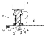
図1は、本発明の第1の実施の形態の遮光絞り機構15の正面図、図2はそのII−II断面図である。
161は、ステッピングモータ16によって回転駆動される出力軸であり、その出力軸161に対して回転自在に嵌合するフランジ151に、遮光羽根152がビス等によって固着されている。
【0020】
照明光線束を遮るための遮光部152aは、遮光羽根152の一端側に円形状に形成されている。154は、フランジ151が出力軸161から抜け出すのを防止するための抜け止め環であり、止めネジ155によって出力軸161の先端部分に固定されている。
【0021】
出力軸161の基部寄りの部分に形成された太径部とフランジ151との間にはコイルバネ153が介装されており、このコイルバネ153の一端側は出力軸161に穿設された孔に差し込まれ、他端側はフランジ151に穿設された孔に差し込まれている。
【0022】
したがって、ステッピングモータ16によって出力軸161が回転駆動されると、それによってコイルバネ153の一端側が軸回りに回転し、その回転運動がコイルバネ153を介して弾力的にフランジ151に伝達される。
【0023】
156は、封入された流体の粘性制動作用によってロッド156aの軸方向の動作を緩衝するダッシュポット(流体緩衝器)であり、ロッド156aの先端が、遮光羽根152に突設されたピン157に回転自在に係合している。
【0024】
このように構成された遮光絞り機構15では、例えば図1に示される絞り全閉状態から、図4に示される光線束100が全く遮られない全開状態の方向にステッピングモータ16を回転駆動すると、出力軸161の回転動作は、ステッピングモータ16の1ステップ毎に大きな速度変化のあるカクッカクッという不連続的な運動になる。
【0025】
しかし、そのような不連続的運動はコイルバネ153の弾力性によって吸収されて、急な動作変化が緩衝されるので、コイルバネ153の他端側とつながっているフランジ151は、ある程度滑らかな回転運動をする。
【0026】
ただし、それだけではコイルバネ153の有するバネ性によって、フランジ151の運動に振動運動が加わるが、遮光羽根152に連結されたダッシュポット156によって、そのような振動が抑制される。
【0027】
その結果、遮光羽根152は、ステッピングモータ16の回転運動に対して若干の遅れを有する滑らかな運動をして、それによってライトガイドファイババンドル5に入射する照明光線束の面積が変化し、被写体に照射される照明光の明るさが滑らかに変化する。
【0028】
なお、実際に装置を設計する際には、コイルバネ153のバネ定数とダッシュポット156の粘性制動係数等を、テレビモニタ30に表示される内視鏡観察画面の明るさが違和感なく変化するように設定すればよい。
【0029】
このようにして、この実施の形態の内視鏡用光源装置においては、制御部22から出力される制御信号に基づいてステッピングモータ16に適宜数の駆動パルスを入力させることによって、図5に示されるように、光線束100が部分的に遮られる任意の位置で遮光羽根152を停止させて照明光の明るさを調整することができ、その遮光羽根152移動の際には、被写体に照射される照明光の明るさが違和感なく滑らかに変化する。
【0030】
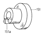
図6は、本発明の第2の実施の形態の遮光絞り機構15の正面図、図7はVII−VII断面を示しており、フランジ151と抜け止め環154とが、回転方向の遊び範囲を越えると当接するようにしたものであり、その他は第1の実施の形態と同じである。
【0031】
この実施の形態のフランジ151には、図8に示されるように、扇状の突起151aが末端側に突出している。そして、IX−IX断面を示す図9に示されるように、その突起151aより幅広に抜け止め環154に形成された扇状の切り欠き154aの中で、突起151aが自由に回動できるように配置されている。
【0032】
その回動幅(遊び範囲)は例えば両側へ10°ずつであり、出力軸161の回転角度が遊び範囲内にある場合は、前述の第1の実施の形態の装置と全く同様に動作する。
【0033】
しかし、出力軸161に直結された抜け止め環154がその遊び範囲を超えて回転すると、切り欠き154aの壁面と突起151aとがぶつかって、フランジ151に直結された遮光羽根152が出力軸161の運動どおりに回転駆動される。
【0034】
したがって、例えば被写体までの距離が急に変化をして照明光の明るさを大きく変える必要がある場合などには、照明光の明るさがステッピングモータ16の回転に同期して遅れなく変化する。ただしその際には、明るさが不連続的に変化する現象は発生する。なお、遊び範囲を作る手段として電磁クラッチ等を用いてもよい。
【0035】
図10は、本発明の第3の実施の形態の遮光絞り機構15の正面図、図11はXI−XI断面を示しており、遮光羽根152の運動を滑らかにするための緩衝手段として流体継手158を利用したものである。
【0036】
この実施の形態の遮光絞り機構15においては、出力軸161に対してアーム161bを介してクランク状に連結された板バネ161aの先端部分が、遮光羽根152に回転中心位置から離れて穿設された孔152bに差し込まれている。
【0037】
遮光羽根152は、振動運動を抑制するために設けられた流体継手158によって、光源装置兼ビデオプロセッサ10のフレーム10aに支持されている。流体継手158には、フレーム10aに連結された固定軸158aと遮光羽根152に連結された回転軸158bとの間に、高粘度の液体158cが封入されている。
【0038】
したがって、ステッピングモータ16が駆動されると、板バネ161aを介して152が流体継手158を中心にして回転運動をするが、板バネ161aの弾力性と流体継手158の粘性抵抗によって、遮光羽根152は、ステッピングモータ16の回転運動に対して若干の遅れを有する滑らかな運動をして、第1の実施の形態と同様に、被写体に照射される照明光の明るさが滑らかに変化をする。
【0039】
【発明の効果】
本発明によれば、ステッピングモータの出力軸の不連続的な回転運動によって駆動される遮光絞りの急な動作変化が緩衝手段によって緩衝されて、遮光絞りが滑らかに動作するので、被写体に照射される照明光の明るさが滑らかに変化をして、観察者に不自然な印象を与えない安定した内視鏡観察を行うことができる。
【図面の簡単な説明】
【図1】本発明の第1の実施の形態の絞り機構の全閉状態の正面図である。
【図2】本発明の第1の実施の形態のII−II断面図である。
【図3】本発明の第1の実施の形態の電子内視鏡装置の全体構成を示すブロック図である。
【図4】本発明の第1の実施の形態の絞り機構の全開状態の正面図である。
【図5】本発明の第1の実施の形態の絞り機構の中間開度状態の正面図である。
【図6】本発明の第2の実施の形態の絞り機構の全閉状態の正面図である。
【図7】本発明の第2の実施の形態のVII−VII断面図である。
【図8】本発明の第2の実施の形態のフランジの斜視図である。
【図9】本発明の第2の実施の形態のIX−IX断面図である。
【図10】本発明の第3の実施の形態の絞り機構の全閉状態の正面図である。
【図11】本発明の第3の実施の形態のXI−XI断面図である。
【符号の説明】
4 ライトガイドファイババンドル
10 光源装置兼ビデオプロセッサ
11 光源ランプ
15 遮光絞り機構
16 ステッピングモータ
151 フランジ
152 遮光羽根
153 コイルバネ
156 ダッシュポット
158 流体継手
161 出力軸
161a 板バネ[0001]
BACKGROUND OF THE INVENTION
The present invention relates to an endoscope light source device for supplying illumination light to an illumination light guide of an endoscope.
[0002]
[Prior art]
In general, an endoscope light source device is a light-shielding diaphragm for partially blocking a light beam in the middle of an illumination light path for causing illumination light emitted from a light source lamp to enter an illumination light guide of an endoscope. Is arranged, and the brightness of the illumination light applied to the subject is adjusted by changing the light shielding area of the illumination optical path by driving the light shielding diaphragm.
[0003]
Especially in electronic endoscopes, it is desirable to keep the brightness of the imaging screen constant, so the operation of the light-shielding diaphragm is always controlled so that the magnitude of the luminance signal in the video signal is constant. A stepping motor is used to drive such a light-shielding diaphragm.
[0004]
[Problems to be solved by the invention]
However, when the shading diaphragm is directly driven by the stepping motor, the discontinuous movement of the stepping motor is transmitted to the shading diaphragm as it is, so the brightness of the illumination light changes stepwise, which is unpleasant for the observer. May give an impression. In particular, when an endoscopic observation image is displayed on a television monitor in a dark room, the tendency increases, which may cause inconvenience in observation.
[0005]
Therefore, an object of the present invention is to provide an endoscope light source device in which the brightness of illumination light changes smoothly even when the light-shielding diaphragm is driven by a stepping motor and does not give an unnatural impression to the observer. And
[0006]
[Means for Solving the Problems]
In order to achieve the above object, an endoscope light source device according to the present invention provides a beam bundle in the middle of an illumination light path for causing illumination light emitted from a light source lamp to enter an illumination light guide of an endoscope. In an endoscope light source device in which a light-shielding diaphragm for partially shielding is disposed and the light-shielding diaphragm is driven by a stepping motor to change the light-shielding area of the light beam, the output shaft of the stepping motor Buffering means for buffering a sudden change in the operation of the light-shielding diaphragm driven by the discontinuous rotational movement is provided so that the light-shielding diaphragm operates smoothly.
[0007]
The buffer means may include a spring member that is interposed between the output shaft of the stepping motor and the light-shielding diaphragm and transmits the driving force of the stepping motor to the light-shielding diaphragm.
[0008]
And the said buffer means may contain the fluid buffer means which suppresses the vibration motion of the said spring member by the effect | action of the viscosity of a fluid.
Further, when the rotational angle of the stepping motor exceeds a predetermined width, the rotational motion of the stepping motor may be directly transmitted to the light-shielding diaphragm without passing through the spring member.
[0009]
DETAILED DESCRIPTION OF THE INVENTION
Embodiments of the present invention will be described with reference to the drawings.
FIG. 3 shows the overall configuration of the electronic endoscope apparatus. For example, a monochrome type charge coupled device (at the imaging position of the subject by the objective
[0010]
The endoscopic observation image is picked up by the solid-state
[0011]
The light source device /
[0012]
An RGB rotation filter in which three color filters of red (R), green (G), and blue (B) are arranged on the same circumference between the incident end face of the light guide fiber bundle 5 and the
[0013]
Therefore, red, green, and blue illumination lights are sequentially incident on the light guide fiber bundle 5 at different times, and the subject is illuminated with the illumination light that changes color in that order.
[0014]
Between the
[0015]
In this light-
[0016]
The imaging signal transmitted to the light source device /
[0017]
The RGB video signals stored in the
[0018]
The digital video signal output from the analog-
[0019]
FIG. 1 is a front view of a light-
[0020]
The
[0021]
A
[0022]
Therefore, when the
[0023]
[0024]
In the light blocking
[0025]
However, such a discontinuous movement is absorbed by the elasticity of the
[0026]
However, by virtue of the spring property of the
[0027]
As a result, the
[0028]
When actually designing the apparatus, the brightness of the endoscopic observation screen displayed on the
[0029]
In this way, in the endoscope light source device of this embodiment, an appropriate number of driving pulses are input to the stepping
[0030]
FIG. 6 is a front view of the light-shielding
[0031]
In the
[0032]
The rotation width (play range) is, for example, 10 ° on both sides. When the rotation angle of the
[0033]
However, when the retaining
[0034]
Therefore, for example, when the distance to the subject suddenly changes and the brightness of the illumination light needs to be greatly changed, the brightness of the illumination light changes without delay in synchronization with the rotation of the stepping
[0035]
FIG. 10 is a front view of the light-shielding
[0036]
In the light-shielding
[0037]
The
[0038]
Therefore, when the stepping
[0039]
【The invention's effect】
According to the present invention, the sudden movement change of the light-shielding diaphragm driven by the discontinuous rotational movement of the output shaft of the stepping motor is buffered by the buffer means, and the light-shielding diaphragm operates smoothly. Therefore, stable endoscopic observation can be performed without giving an unnatural impression to the observer.
[Brief description of the drawings]
FIG. 1 is a front view showing a fully closed state of a diaphragm mechanism according to a first embodiment of the present invention.
FIG. 2 is a II-II sectional view of the first embodiment of the present invention.
FIG. 3 is a block diagram showing an overall configuration of the electronic endoscope apparatus according to the first embodiment of the present invention.
FIG. 4 is a front view of the aperture mechanism in the fully opened state according to the first embodiment of the present invention.
FIG. 5 is a front view showing an intermediate opening state of the aperture mechanism according to the first embodiment of the present invention.
FIG. 6 is a front view of the aperture mechanism in the fully closed state according to the second embodiment of the present invention.
FIG. 7 is a sectional view taken along the line VII-VII of the second embodiment of the present invention.
FIG. 8 is a perspective view of a flange according to a second embodiment of the present invention.
FIG. 9 is a cross-sectional view taken along the line IX-IX of the second embodiment of the present invention.
FIG. 10 is a front view of a throttling mechanism according to a third embodiment of the present invention in a fully closed state.
FIG. 11 is a cross-sectional view taken along the line XI-XI of the third embodiment of the present invention.
[Explanation of symbols]
4 light
Claims (3)
上記ステッピングモータの出力軸の不連続的な回転運動によって駆動される上記遮光絞りの急な動作変化を緩衝するための、上記ステッピングモータの出力軸と上記遮光絞りとの間に介装されて上記ステッピングモータの駆動力を上記遮光絞りに伝達するばね部材を含む緩衝手段を設けて、上記遮光絞りが滑らかに動作するようにしたことを特徴とする内視鏡用光源装置。A light-shielding stop for partially blocking the light bundle is disposed in the middle of the illumination light path for causing the illumination light emitted from the light source lamp to enter the illumination light guide of the endoscope. In the endoscope light source device that changes the light shielding area of the light bundle by driving with
Interposing between the output shaft of the stepping motor and the light-shielding diaphragm for buffering sudden changes in the operation of the light-shielding diaphragm driven by discontinuous rotational movement of the output shaft of the stepping motor. A light source device for an endoscope , wherein a buffer means including a spring member for transmitting a driving force of a stepping motor to the light-shielding diaphragm is provided so that the light-shielding diaphragm operates smoothly.
Priority Applications (1)
| Application Number | Priority Date | Filing Date | Title |
|---|---|---|---|
| JP31513395A JP3665397B2 (en) | 1995-12-04 | 1995-12-04 | Endoscope light source device |
Applications Claiming Priority (1)
| Application Number | Priority Date | Filing Date | Title |
|---|---|---|---|
| JP31513395A JP3665397B2 (en) | 1995-12-04 | 1995-12-04 | Endoscope light source device |
Publications (2)
| Publication Number | Publication Date |
|---|---|
| JPH09154816A JPH09154816A (en) | 1997-06-17 |
| JP3665397B2 true JP3665397B2 (en) | 2005-06-29 |
Family
ID=18061809
Family Applications (1)
| Application Number | Title | Priority Date | Filing Date |
|---|---|---|---|
| JP31513395A Expired - Fee Related JP3665397B2 (en) | 1995-12-04 | 1995-12-04 | Endoscope light source device |
Country Status (1)
| Country | Link |
|---|---|
| JP (1) | JP3665397B2 (en) |
Families Citing this family (1)
| Publication number | Priority date | Publication date | Assignee | Title |
|---|---|---|---|---|
| JP6055639B2 (en) * | 2012-09-27 | 2016-12-27 | Hoya株式会社 | Rotating chopper driving device in endoscope light source device, and assembling method of rotating chopper driving device in endoscope light source device |
-
1995
- 1995-12-04 JP JP31513395A patent/JP3665397B2/en not_active Expired - Fee Related
Also Published As
| Publication number | Publication date |
|---|---|
| JPH09154816A (en) | 1997-06-17 |
Similar Documents
| Publication | Publication Date | Title |
|---|---|---|
| US4862253A (en) | Apparatus for converting a video processor | |
| US9049359B2 (en) | Camera body | |
| JPH0755525Y2 (en) | Light-shielding device for lens barrel of lens shutter type camera | |
| JP2003521200A (en) | Compact through-the-lens digital camera | |
| US8077403B2 (en) | Lens barrel | |
| JPS63182621A (en) | Light source device for endoscope | |
| JP4200408B2 (en) | Imaging device | |
| JP3665397B2 (en) | Endoscope light source device | |
| KR100379763B1 (en) | Device for recording three dimensional video that can be watched without 3D glasses | |
| JPS6269222A (en) | Endoscope recording device | |
| AU2002249657A1 (en) | Apparatus for recording three dimensional video and movie camera | |
| JPH11183809A (en) | Image pickup device for endoscope | |
| JP2002341223A (en) | Zoom lens barrel | |
| JPS6396623A (en) | Light source device for endoscope | |
| JP4429641B2 (en) | Stereo microscope | |
| JPH03156411A (en) | Lens barrel | |
| JP2004245978A (en) | Fluorescence microscope | |
| JPH10248808A (en) | Light source device for endoscope | |
| JP4317285B2 (en) | Endoscopic imaging device | |
| JPS6141430A (en) | Iris apparatus of light source apparatus for endoscope | |
| JPH10115787A (en) | Multi-field optical device | |
| KR20020061093A (en) | Device for recording three dimensional video | |
| JP2000098444A (en) | Light amount adjusting device, lens barrel having the light amount adjusting device, and camera | |
| JP2015118208A (en) | Intermediate adapter | |
| JPH0738895Y2 (en) | Focusing mechanism for direct-view imaging device |
Legal Events
| Date | Code | Title | Description |
|---|---|---|---|
| A977 | Report on retrieval |
Free format text: JAPANESE INTERMEDIATE CODE: A971007 Effective date: 20040331 |
|
| A131 | Notification of reasons for refusal |
Free format text: JAPANESE INTERMEDIATE CODE: A131 Effective date: 20041130 |
|
| A521 | Written amendment |
Free format text: JAPANESE INTERMEDIATE CODE: A523 Effective date: 20050119 |
|
| TRDD | Decision of grant or rejection written | ||
| A01 | Written decision to grant a patent or to grant a registration (utility model) |
Free format text: JAPANESE INTERMEDIATE CODE: A01 Effective date: 20050317 |
|
| A61 | First payment of annual fees (during grant procedure) |
Free format text: JAPANESE INTERMEDIATE CODE: A61 Effective date: 20050401 |
|
| R150 | Certificate of patent or registration of utility model |
Free format text: JAPANESE INTERMEDIATE CODE: R150 |
|
| FPAY | Renewal fee payment (event date is renewal date of database) |
Free format text: PAYMENT UNTIL: 20090408 Year of fee payment: 4 |
|
| FPAY | Renewal fee payment (event date is renewal date of database) |
Free format text: PAYMENT UNTIL: 20090408 Year of fee payment: 4 |
|
| FPAY | Renewal fee payment (event date is renewal date of database) |
Free format text: PAYMENT UNTIL: 20100408 Year of fee payment: 5 |
|
| FPAY | Renewal fee payment (event date is renewal date of database) |
Free format text: PAYMENT UNTIL: 20100408 Year of fee payment: 5 |
|
| FPAY | Renewal fee payment (event date is renewal date of database) |
Free format text: PAYMENT UNTIL: 20110408 Year of fee payment: 6 |
|
| FPAY | Renewal fee payment (event date is renewal date of database) |
Free format text: PAYMENT UNTIL: 20120408 Year of fee payment: 7 |
|
| LAPS | Cancellation because of no payment of annual fees |