JP3663653B2 - Hydrogen generator - Google Patents
Hydrogen generator Download PDFInfo
- Publication number
- JP3663653B2 JP3663653B2 JP03879095A JP3879095A JP3663653B2 JP 3663653 B2 JP3663653 B2 JP 3663653B2 JP 03879095 A JP03879095 A JP 03879095A JP 3879095 A JP3879095 A JP 3879095A JP 3663653 B2 JP3663653 B2 JP 3663653B2
- Authority
- JP
- Japan
- Prior art keywords
- supply pipe
- internal space
- water
- catalyst
- methanol
- Prior art date
- Legal status (The legal status is an assumption and is not a legal conclusion. Google has not performed a legal analysis and makes no representation as to the accuracy of the status listed.)
- Expired - Fee Related
Links
Images

Description
【0001】
【産業上の利用分野】
本発明は、水素発生装置に関する。
【0002】
【従来の技術】
この種の従来技術としては、水蒸気改質法及び部分酸化改質法を用いた装置が知られている。
【0003】
前者の水蒸気改質法は、反応管内にメタノールと水を混入して、反応管に熱を加えることによって両者を下式の如く反応させ、水素を得るものである。
【0004】
CH3 OH + H2 O → CO2 + 3H2
上記水蒸気改質法の長所としては、得られる改質ガス中の水素濃度が高いことが挙げられるが、短所として▲1▼水の貯蔵手段及び加熱手段が必要であるため構造が複雑であり小型化が困難であること、▲2▼吸熱反応であるために加熱が必要であること、が挙げられる。このため、装置の搭載性(装置が大型化する)、始動性(始動開始から十分な水素が得られるまでに時間が掛かる)、応答性(発生される水素量を一時的に増大させたい場合に必要量が発生されるまでに時間が掛かる)が悪いという問題点があった。
【0005】
このような問題点から後者の部分酸化改質法が提案されている。この方法を用いた装置としては、特開昭62−59501号公報に開示されるような装置が知られている。これは、メタノールと酸素(空気)の混合物を触媒が収納されたハウジング内に供給管を通じて流入させることによって、両者を下式の如く反応させ、水素を得るものである。
【0006】
CH3 OH + 1/2O2 → CO2 + 2H2
上記部分酸化改質法の長所としては、▲1▼構造がシンプルであるために装置を小型化できること、▲2▼発熱反応であるために反応を起こさせるための熱源が不要であること、が挙げられる。このため、装置の搭載性(即ち、小型化)、始動性、応答性を良好なものとすることができる。
【0007】
又、特開昭62−59501号公報に開示される水素発生装置では、一部不完全な反応により生じる一酸化炭素を低減するために、メタノール中に水を混入させて、水と一酸化炭素とを下式の如く反応させることにより低減させる方法が採用されている。
【0008】
H2 O + CO → CO2 + H2
【0009】
【発明が解決しようとする課題】
上記した水と一酸化炭素とは、低温度(150℃程度)の方が反応が促進されるが、上記したようにメタノールに水を混入する方法では、ホットスポット領域(メタノールと酸素とが活発に反応する領域であり、通常作動時は300℃〜400℃のとなっている)にて水と一散化炭素とが反応されるために、一酸化炭素の低減効果が小さい。
【0010】
本発明は、一酸化炭素の低減効果が大きい水素発生装置の提供を技術的課題とする。
【0011】
【課題を解決するための手段】
上記した技術的課題を解決するため請求項1の発明において講じた技術的手段は、内部空間内に触媒が充満されているハウジングと、内部空間内の上流側に開口した第1供給管と、内部空間内で反応して発生される改質ガスが内部空間から流れ出るための吹き出し管と、第1供給管に接続されたメタノール供給手段と、第1供給管に接続された酸素供給手段とを備えた水素発生装置において、内部空間内の下流側に開口した第2供給管と、第2供給管に水を供給する水供給手段とを備えたことである。
【0012】
一酸化炭素の低減効果を更に向上させるために、請求項2の発明において講じた技術的手段は、第2供給管の前記開口部を、第1供給管の開口部に対向した位置に配設したことである。
【0013】
一酸化炭素の低減効果を維持するために、請求項3の発明において講じた技術的手段は、内部空間内の下流側に配設され触媒の温度を低下させる熱交換手段を備えたことである。
【0014】
【作用】
請求項1の発明においては、メタノール供給手段と酸素供給手段より第1供給管に供給されたメタノールと酸素は、第1供給管の開口から触媒中に吹き出される。メタノールと酸素の混合流体は、ホットスポット領域(第1供給管の開口部近傍)において触媒に接触することによって反応する。この反応によって発生した改質ガス(二酸化炭素と水素の混合ガス)は、吹き出し管より順次吹き出される。
【0015】
一方、反応が一部不完全により発生した一酸化炭素は、水供給手段から第2供給管を通って内部空間内に流入した水と下流側の低温領域(150℃程度)にて反応し、二酸化炭素と水素になって吹き出し管より順次吹き出される。これにより、一酸化炭素が低減される。
【0016】
請求項2の発明においては、第2供給管の開口部が第1供給管の開口部の対向した位置に配設されているために、メタノールと酸素が反応して発生した改質ガスの下流域(一酸化炭素の濃度が低い)で高濃度の水による高い反応確率が得られ、一酸化炭素の低減効果を更に向上させることができる。
【0017】
請求項3の発明においては、内部空間の下流側の触媒にホットスポット領域の熱が伝わり、内部空間下流側の触媒の温度が上がり過ぎるのを、熱交換手段が内部空間下流側の触媒の温度を奪うことにて防止することができるために、内部空間の下流側の触媒温度を水と一酸化炭素が活発に反応する温度領域に保つことができ、一酸化炭素の低減効果を維持することができる。
【0018】
【実施例】
本発明に係る実施例を図面に基づいて説明する。
【0019】
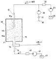
図1は本発明に係る第1実施例の水素発生装置の構成図である。同図において、ハウジング10の内部空間10a内には、触媒11が充満されている。触媒11には、銅系触媒、ニッケル系触媒、貴金属系触媒等が用いられる。
【0020】
ハウジング10の図中上面には、開口部12aがハウジングの内部空間10a内に開口した第1供給管12が挿入されている。この第1供給管12の開口部12aは内部空間10aの図中上部(上流側)に位置している。
【0021】
第1供給管12は、後述するメタノール供給手段及び酸素供給手段に接続されている。メタノール供給手段は、液体のメタノールを貯えるメタノールタンク20と、このメタノールタンク20内に貯えられているメタノールを第1供給管12に順次供給するためのメタノールポンプ21と、液体のメタノールを気化するための気化器22とから構成されている。酸素供給手段は、酸素(空気)を取り入れる取り入れ口30と、この取り入れ口30から吸い込んだ酸素のゴミを取り除くフィルター31と、酸素を第1供給管12に順次供給するためのエアポンプ32とから構成されている。
【0022】
一方、ハウジング10の図中下面には、ハウジング10内で反応して発生する改質ガスが流れだすための吹き出し管14が取り付けられている。この吹き出し管14を流れる改質ガスは、例えば燃料電池に供給されて電力の発生源として利用される。
【0023】
吹き出し管14内には、水供給手段に接続される第2供給管15が挿通されている。第2供給管15の開口部15aは、内部空間10aの下方で且つ第1供給管12の開口部12aに対向した位置に配設されている。
【0024】
水供給手段は、水を貯える水タンク40と、この水タンク40内に貯えられている水を第2供給管15に順次供給するウォータポンプ41と、水を気化して水蒸気とするための気化器42とから構成されている。
【0025】
尚、メタノールポンプ21、エアポンプ32、ウォータポンプ41の作動制御は、図示しない制御装置により成される。
【0026】
上記した第1実施例の水素発生装置の作用を説明する。
【0027】
制御装置によりメタノールポンプ21、エアポンプ32、ウォータポンプ41が作動されると、第1供給管12よりメタノールと酸素の混合流体が内部空間10aに供給されると共に、第2供給管15より水蒸気が内部空間に供給される。
【0028】
第1供給管より供給される混合流体は、ホットスポット領域HSにて触媒に接触することにより反応して、水素と二酸化炭素とからなる改質ガスを発生する。
【0029】
このとき、一部不完全な反応により生じる一酸化炭素は、内部空間10a内の図中下方(下流)にて、第2供給管15より図中上方に向けて吹き出される水蒸気(水)と反応して二酸化炭素と水素になる。
【0030】
上記第1実施例の水素発生装置においては、一酸化炭素と水は内部空間10aの下流側の低温領域(150℃程度)にて反応されるために、水と一酸化炭素との反応が促進されて一酸化炭素の低減効果が大きいものである。
【0031】
又、第1実施例の水素発生装置においては、第2供給管15の開口部15aが第1供給管12の開口部12aの対向した位置に配設されているために、改質ガスと供給された水蒸気の流れが対向し、改質ガス下流域の一酸化炭素濃度の低い領域で高い密度の高い水蒸気が当たることになり、一酸化炭素の低減効果を更に向上させることができる。
【0032】
図2は本発明に係る第2実施例の水素発生装置のハウジングとその周辺の構成図である。同図において、上記第1実施例の水素発生装置との相違点についてのみ説明する。
【0033】
図2において、第1供給管12のメタノール通路12bは、ハウジング10の図中下方より挿通されていて、触媒11中の熱を第1供給管12に効率よく伝達させるためにフィン状を呈した熱交換部材(熱交換手段)50が複数設けられている。一方、第1供給管12の酸素通路12cは、ハウジング10の下方より内部空間10a内に挿通されて内部空間10aの内周面に沿って螺旋状に配設されている。そして、内部空間10aの中央付近にてメタノール通路12bと酸素通路12cの両者は接続され、更にその開口部12aは図中上方に向けて開口している。
【0034】
次に、第2実施例の水素発生装置の作用について説明する。
【0035】
メタノールポンプ21及び酸素ポンプ32から供給されるメタノールと酸素は、それぞれの通路12b、12cを通って混合され、第1供給管12の開口部12aから内部空間10aに供給される。第1供給管12より供給される混合流体は、ホットスポット領域HSにて触媒に接触することにより反応して、水素と二酸化炭素とからなる改質ガスを発生する。
【0036】
第2実施例においては、内部空間10a内に配設されている第1供給管12のメタノール通路12bは熱交換部材50を介して触媒11の熱を吸収し、酸素通路12cは直接触媒11の熱を吸収して、下流側に位置する触媒11の熱を奪う構成となっている。このため、内部空間10aの下流側の触媒11に、ホットスポット領域HSの熱が伝わり、内部空間10aの下流側の触媒11の温度が上がり過ぎるのを、熱交換部材50及び酸素通路12cが内部空間10a下流側の触媒11の温度を奪うことにて防止することができるために、内部空間10aの下流側の触媒温度を水と一酸化炭素が活発に反応する温度領域に保ことがができ、一酸化炭素の低減効果を維持することができる。
【0037】
【発明の効果】
請求項1の発明においては、ハウジング内部空間の下流側に水が供給され、水と一酸化炭素とは下流側の低温領域にて反応されるために、水と一酸化炭素との反応が促進されて一酸化炭素の低減効果が大きいものである。
【0038】
請求項2の発明においては、第2供給管の開口部が第1供給管の開口部の対向した位置に配設されているために、改質ガスと供給された水蒸気の流れが対向し、改質ガス下流域の一酸化炭素濃度の低い領域で高い密度の高い水蒸気が当たることになり、一酸化炭素の低減効果を更に向上させることができる。
【0039】
請求項3の発明においては、内部空間の下流側の触媒にホットスポット領域の熱が伝わり、内部空間下流側の触媒の温度が上がり過ぎるのを、熱交換手段が内部空間下流側の触媒の温度を奪うことにて防止することができるために、内部空間の下流側の触媒温度を水と一酸化炭素が活発に反応する温度領域に保つことができ、一酸化炭素の低減効果を維持することができる。
【図面の簡単な説明】
【図1】本発明に係る第1実施例の水素発生装置の構成図を示す。
【図2】本発明に係る第2実施例の水素発生装置のハウジングとその周辺の構成図を示す。
【符号の説明】
10・・・ハウジング
10a・・・内部空間
11・・・触媒
12・・・第1供給管
14・・・吹き出し管
15・・・第2供給管
20・・・メタノールタンク(メタノール供給手段)
21・・・メタノールポンプ(メタノール供給手段)
22・・・気化器(酸素供給手段)
30・・・吸い込み口(酸素供給手段)
31・・・フィルター(酸素供給手段)
32・・・酸素ポンプ(酸素供給手段)
40・・・水タンク(水供給手段)
41・・・ウォータポンプ(水供給手段)
42・・・気化器
50・・・熱交換部材(熱交換手段)[0001]
[Industrial application fields]
The present invention relates to a hydrogen generator.
[0002]
[Prior art]
As this type of prior art, an apparatus using a steam reforming method and a partial oxidation reforming method is known.
[0003]
In the former steam reforming method, methanol and water are mixed in a reaction tube, and heat is applied to the reaction tube to cause both to react as shown in the following equation to obtain hydrogen.
[0004]
CH3 OH + H2 O → CO2 + 3H2
The advantage of the steam reforming method is that the hydrogen concentration in the resulting reformed gas is high. However, the disadvantage is that (1) water storage means and heating means are required, so the structure is complicated and compact. And (2) heat is necessary because of the endothermic reaction. For this reason, if you want to temporarily increase the mountability of the device (the device becomes larger), startability (it takes time until sufficient hydrogen is obtained from the start of startup), and responsiveness It takes a long time until the necessary amount is generated).
[0005]
In view of such problems, the latter partial oxidation reforming method has been proposed. As an apparatus using this method, an apparatus disclosed in Japanese Patent Application Laid-Open No. 62-59501 is known. In this method, a mixture of methanol and oxygen (air) is caused to flow through a supply pipe into a housing in which a catalyst is accommodated, whereby both are reacted as in the following formula to obtain hydrogen.
[0006]
CH3 OH + 1 / 2O2 → CO2 + 2H2
The advantages of the partial oxidation reforming method are: (1) the structure is simple and the apparatus can be miniaturized; and (2) the exothermic reaction eliminates the need for a heat source for causing the reaction. Can be mentioned. For this reason, the mountability (that is, downsizing), startability, and response of the apparatus can be improved.
[0007]
In addition, in the hydrogen generator disclosed in Japanese Patent Application Laid-Open No. 62-59501, water and carbon monoxide are mixed by mixing water into methanol in order to reduce carbon monoxide generated due to incomplete reaction. The method of reducing by making it react like following Formula is employ | adopted.
[0008]
H2 O + CO → CO2 + H2
[0009]
[Problems to be solved by the invention]
The reaction between water and carbon monoxide is promoted at a low temperature (about 150 ° C.). However, in the method of mixing water in methanol as described above, the hot spot region (methanol and oxygen are active). Since water reacts with carbonized carbon in a normal operation, the temperature is 300 ° C. to 400 ° C.), so the effect of reducing carbon monoxide is small.
[0010]
This invention makes it a technical subject to provide the hydrogen generator with the large reduction effect of carbon monoxide.
[0011]
[Means for Solving the Problems]
In order to solve the above technical problem, the technical means taken in the invention of claim 1 includes a housing in which the internal space is filled with a catalyst, a first supply pipe that is opened upstream in the internal space, and A blowout pipe for the reformed gas generated by reaction in the internal space to flow out of the internal space, a methanol supply means connected to the first supply pipe, and an oxygen supply means connected to the first supply pipe The provided hydrogen generator includes a second supply pipe that opens to the downstream side in the internal space, and water supply means that supplies water to the second supply pipe.
[0012]
In order to further improve the reduction effect of carbon monoxide, the technical means taken in the invention of claim 2 is arranged such that the opening of the second supply pipe is disposed at a position facing the opening of the first supply pipe. It is that.
[0013]
In order to maintain the reduction effect of carbon monoxide, the technical means taken in the invention of claim 3 is provided with a heat exchange means disposed downstream in the internal space to lower the temperature of the catalyst. .
[0014]
[Action]
In the first aspect of the invention, the methanol and oxygen supplied from the methanol supply means and the oxygen supply means to the first supply pipe are blown into the catalyst from the opening of the first supply pipe. The mixed fluid of methanol and oxygen reacts by contacting the catalyst in the hot spot region (near the opening of the first supply pipe). The reformed gas (mixed gas of carbon dioxide and hydrogen) generated by this reaction is sequentially blown out from the blowing pipe.
[0015]
On the other hand, carbon monoxide generated due to partial incomplete reaction reacts with water flowing into the internal space from the water supply means through the second supply pipe in the low temperature region (about 150 ° C.) on the downstream side, It becomes carbon dioxide and hydrogen and is blown out from the blow-out tube. Thereby, carbon monoxide is reduced.
[0016]
In the invention of claim 2, since the opening of the second supply pipe is disposed at a position opposite to the opening of the first supply pipe, the reformed gas generated by the reaction of methanol and oxygen is reduced. In the basin (the concentration of carbon monoxide is low), a high reaction probability is obtained with a high concentration of water, and the effect of reducing carbon monoxide can be further improved.
[0017]
In the invention of claim 3, the heat in the hot spot region is transferred to the catalyst on the downstream side of the internal space and the temperature of the catalyst on the downstream side of the internal space rises too much. The catalyst temperature on the downstream side of the internal space can be kept in a temperature range where water and carbon monoxide react actively, and the effect of reducing carbon monoxide is maintained. Can do.
[0018]
【Example】
Embodiments according to the present invention will be described with reference to the drawings.
[0019]
FIG. 1 is a configuration diagram of a hydrogen generator according to a first embodiment of the present invention. In the figure, the
[0020]
A
[0021]
The
[0022]
On the other hand, a blow-out
[0023]
A
[0024]
The water supply means includes a
[0025]
The operation control of the
[0026]
The operation of the hydrogen generator of the first embodiment will be described.
[0027]
When the
[0028]
The mixed fluid supplied from the first supply pipe reacts by contacting the catalyst in the hot spot region HS to generate a reformed gas composed of hydrogen and carbon dioxide.
[0029]
At this time, carbon monoxide generated due to a partially incomplete reaction is steam (water) blown out upward in the figure from the
[0030]
In the hydrogen generator of the first embodiment, since carbon monoxide and water are reacted in a low temperature region (about 150 ° C.) downstream of the
[0031]
Further, in the hydrogen generator of the first embodiment, since the opening 15a of the
[0032]
FIG. 2 is a configuration diagram of a housing and its surroundings of a hydrogen generator according to a second embodiment of the present invention. In the figure, only differences from the hydrogen generator of the first embodiment will be described.
[0033]
In FIG. 2, the
[0034]
Next, the operation of the hydrogen generator of the second embodiment will be described.
[0035]
Methanol and oxygen supplied from the
[0036]
In the second embodiment, the
[0037]
【The invention's effect】
In the first aspect of the invention, water is supplied to the downstream side of the internal space of the housing, and the water and carbon monoxide are reacted in a low temperature region on the downstream side, so that the reaction between water and carbon monoxide is accelerated. Therefore, the effect of reducing carbon monoxide is great.
[0038]
In the invention of claim 2, since the opening of the second supply pipe is disposed at a position opposed to the opening of the first supply pipe, the reformed gas and the flow of the supplied water vapor face each other, High density water vapor hits in the region of low carbon monoxide concentration in the reformed gas downstream region, and the effect of reducing carbon monoxide can be further improved.
[0039]
In the invention of claim 3, the heat in the hot spot region is transferred to the catalyst on the downstream side of the internal space and the temperature of the catalyst on the downstream side of the internal space rises too much. The catalyst temperature on the downstream side of the internal space can be kept in a temperature range where water and carbon monoxide react actively, and the effect of reducing carbon monoxide is maintained. Can do.
[Brief description of the drawings]
FIG. 1 shows a configuration diagram of a hydrogen generator according to a first embodiment of the present invention.
FIG. 2 shows a configuration diagram of a housing of a hydrogen generator according to a second embodiment of the present invention and its surroundings.
[Explanation of symbols]
DESCRIPTION OF
21 ... Methanol pump (methanol supply means)
22 ... Vaporizer (oxygen supply means)
30 ... Suction port (oxygen supply means)
31 ... Filter (oxygen supply means)
32 ... Oxygen pump (oxygen supply means)
40 ... Water tank (water supply means)
41 ... Water pump (water supply means)
42 ...
Claims (3)
前記内部空間内の上流側に開口した第1供給管と、
前記内部空間内で反応して発生される改質ガスが前記内部空間から流れ出るための吹き出し管と、
前記第1供給管に接続されたメタノール供給手段と、
前記第1供給管に接続された酸素供給手段と
を備えた水素発生装置において、
前記内部空間内の下流側に開口した第2供給管と、
該第2供給管に水を供給する水供給手段と
を備えたことを特徴とする水素発生装置。A housing filled with catalyst in the internal space;
A first supply pipe that opens to the upstream side in the internal space;
A blowout pipe for the reformed gas generated by reaction in the internal space to flow out of the internal space;
Methanol supply means connected to the first supply pipe;
In a hydrogen generator comprising an oxygen supply means connected to the first supply pipe,
A second supply pipe opened to the downstream side in the internal space;
A hydrogen generator comprising water supply means for supplying water to the second supply pipe.
Priority Applications (1)
| Application Number | Priority Date | Filing Date | Title |
|---|---|---|---|
| JP03879095A JP3663653B2 (en) | 1995-02-27 | 1995-02-27 | Hydrogen generator |
Applications Claiming Priority (1)
| Application Number | Priority Date | Filing Date | Title |
|---|---|---|---|
| JP03879095A JP3663653B2 (en) | 1995-02-27 | 1995-02-27 | Hydrogen generator |
Publications (2)
| Publication Number | Publication Date |
|---|---|
| JPH08231201A JPH08231201A (en) | 1996-09-10 |
| JP3663653B2 true JP3663653B2 (en) | 2005-06-22 |
Family
ID=12535109
Family Applications (1)
| Application Number | Title | Priority Date | Filing Date |
|---|---|---|---|
| JP03879095A Expired - Fee Related JP3663653B2 (en) | 1995-02-27 | 1995-02-27 | Hydrogen generator |
Country Status (1)
| Country | Link |
|---|---|
| JP (1) | JP3663653B2 (en) |
Families Citing this family (3)
| Publication number | Priority date | Publication date | Assignee | Title |
|---|---|---|---|---|
| US6746650B1 (en) * | 1999-06-14 | 2004-06-08 | Utc Fuel Cells, Llc | Compact, light weight methanol fuel gas autothermal reformer assembly |
| JP4534277B2 (en) * | 1999-10-06 | 2010-09-01 | トヨタ自動車株式会社 | Reformer |
| DE60034223T2 (en) * | 1999-12-28 | 2007-08-23 | Daikin Industries, Ltd. | SHIFT REACTOR WITH HEAT EXCHANGER |
-
1995
- 1995-02-27 JP JP03879095A patent/JP3663653B2/en not_active Expired - Fee Related
Also Published As
| Publication number | Publication date |
|---|---|
| JPH08231201A (en) | 1996-09-10 |
Similar Documents
| Publication | Publication Date | Title |
|---|---|---|
| US7678481B2 (en) | Fuel cell system with a fuel tank configured to store a fuel at a pressure higher than atmospheric pressure | |
| WO1996026892A1 (en) | Hydrogen generator | |
| JP3857119B2 (en) | Steam reformer and membrane envelope | |
| JPH07315801A (en) | System for producing high-purity hydrogen, production of high-purity hydrogen and fuel cell system | |
| US5618322A (en) | Reformer for fuel cell system | |
| JP2005530083A (en) | Reduction of nitrogen oxides using reformate generated from engine fuel and water and / or air | |
| JP2002227730A (en) | Gas engine | |
| JP3663653B2 (en) | Hydrogen generator | |
| JP2001080904A (en) | Fuel reformer | |
| JP3738464B2 (en) | Hydrogen generator | |
| JPH11278806A (en) | Fuel cell plant | |
| JP2003123815A (en) | Fuel cell system | |
| JP2002175820A (en) | Fuel cell power supply equipment | |
| JP3282066B2 (en) | Fuel cell system | |
| JPH06264732A (en) | Exhaust gas purifying catalyst overheating preventing device of internal combustion engine | |
| JP4968984B2 (en) | Fuel cell reformer | |
| JPH07232901A (en) | Fuel reformer | |
| JP3676335B2 (en) | Fuel cell system | |
| JP2670168B2 (en) | Hydrogen raw material reformer | |
| JP2004319213A (en) | Hydrogen generating device for portable fuel cell | |
| JP3484921B2 (en) | Gas engine with gas fuel reformer | |
| JPH03218902A (en) | Method for starting raw hydrogen material reformer | |
| JP2789201B2 (en) | Cooling device for fuel cell reformer | |
| JP2000219501A (en) | Reforming device | |
| JP2004127624A (en) | Fuel cell system |
Legal Events
| Date | Code | Title | Description |
|---|---|---|---|
| TRDD | Decision of grant or rejection written | ||
| A01 | Written decision to grant a patent or to grant a registration (utility model) |
Free format text: JAPANESE INTERMEDIATE CODE: A01 Effective date: 20050308 |
|
| A61 | First payment of annual fees (during grant procedure) |
Free format text: JAPANESE INTERMEDIATE CODE: A61 Effective date: 20050321 |
|
| LAPS | Cancellation because of no payment of annual fees |