JP3663377B2 - Data storage device, read data processing device, and read data processing method - Google Patents
Data storage device, read data processing device, and read data processing method Download PDFInfo
- Publication number
- JP3663377B2 JP3663377B2 JP2001325696A JP2001325696A JP3663377B2 JP 3663377 B2 JP3663377 B2 JP 3663377B2 JP 2001325696 A JP2001325696 A JP 2001325696A JP 2001325696 A JP2001325696 A JP 2001325696A JP 3663377 B2 JP3663377 B2 JP 3663377B2
- Authority
- JP
- Japan
- Prior art keywords
- data
- read
- error
- value
- read data
- Prior art date
- Legal status (The legal status is an assumption and is not a legal conclusion. Google has not performed a legal analysis and makes no representation as to the accuracy of the status listed.)
- Expired - Fee Related
Links
- 238000013500 data storage Methods 0.000 title claims description 22
- 238000003672 processing method Methods 0.000 title description 5
- 238000000034 method Methods 0.000 claims description 30
- 238000010586 diagram Methods 0.000 description 15
- 208000011580 syndromic disease Diseases 0.000 description 15
- 238000011084 recovery Methods 0.000 description 10
- 230000006870 function Effects 0.000 description 8
- 230000007547 defect Effects 0.000 description 2
- 230000002950 deficient Effects 0.000 description 2
- 230000000694 effects Effects 0.000 description 2
- 230000001419 dependent effect Effects 0.000 description 1
- 239000000428 dust Substances 0.000 description 1
- 239000000284 extract Substances 0.000 description 1
Images


Classifications
-
- G—PHYSICS
- G11—INFORMATION STORAGE
- G11B—INFORMATION STORAGE BASED ON RELATIVE MOVEMENT BETWEEN RECORD CARRIER AND TRANSDUCER
- G11B20/00—Signal processing not specific to the method of recording or reproducing; Circuits therefor
- G11B20/10—Digital recording or reproducing
- G11B20/18—Error detection or correction; Testing, e.g. of drop-outs
- G11B20/1806—Pulse code modulation systems for audio signals
- G11B20/1809—Pulse code modulation systems for audio signals by interleaving
Landscapes
- Engineering & Computer Science (AREA)
- Multimedia (AREA)
- Signal Processing (AREA)
- Error Detection And Correction (AREA)
- Detection And Correction Of Errors (AREA)
- Signal Processing For Digital Recording And Reproducing (AREA)
Description
【0001】
【発明の属する技術分野】
本発明は、ハード・ディスク・ドライブに代表されるデータ記憶装置に関し、特に、データ記憶媒体から読み出したデータのエラーの判定、さらにはエラーデータの訂正に関するものである。
【0002】
【従来の技術】
ハード・ディスク・ドライブは最も普及しているコンピュータの外部記憶装置の一つである。ハード・ディスク・ドライブの記憶媒体である磁気ディスクは、周知のようにディスク表面を木の年輪状に分割したトラックをさらに放射状に区切ったセクタをデータの記録最小単位としている。磁気ディスク外周になるほど線記録密度を高くすることができる。そこで、現在磁気ディスクのデータ記録方式として主流をなすゾーン・ビット・レコーディング(Zoned Bit Recording)方式では、全てのトラックをいくつかのゾーンにグループ分けし、各ゾーン内では線記録密度を一定とする。すると、セクタの長さは通常512バイト(bytes)であるから、磁気ディスクの外周に近いトラックほどセクタ数は多くなる。
ハード・ディスク・ドライブは、磁気ディスクに記憶されているデータを読み出し、または磁気ディスクにデータを書き込むための磁気ヘッドを備えている。この磁気ヘッドは、VCM(Voice Coil Motor)によって揺動するアクチュエータ機構に装着されている。
磁気ヘッドがデータの読み出しまたはデータの書き込みを行う場合、アクチュエータ機構を駆動することにより、磁気ヘッドを所定のトラックに移動かつ位置決めする。磁気ヘッドは、磁気ディスク上に記憶されたサーボ情報を手がかりに所定の位置への移動制御がなされる。
【0003】
ハード・ディスク・ドライブにおいて、単位面積当たりの記録密度が非常に大きなものとなり、信号処理系のS/Nが低くなり、磁気ディスク上の磁気的欠陥の存在が無視できなくなる。そのため、磁気ディスク上のデフェクトが存在しても読み書きされるデータの信頼性を高めるために、エラー訂正が重要になってきている。
エラー訂正は、読み出したデータがエラーを含んでいる場合などに行われる。エラーは、磁気ディスク上に形成された磁気層の剥がれや、磁気ヘッドとの擦れによるスクラッチ、磁気ディスク上のゴミなどにより発生する。ハード・ディスク・ドライブは、このエラー訂正のために磁気ディスク上に、1セクタのデータ(通常512バイト)毎に、それに基づくパリティを数10バイト付加している。このパリティをECC(エラー訂正符号:Error Correcting Code)という。読み出し時には、ハード・ディスク・ドライブに設けられたECC回路で読み出されたデータと読み出されたパリティ(ECC)からシンドロームを生成し、そのシンドロームからエラー位置の検出を行うとともにエラー訂正処理が施される。
エラー訂正能力は、一例として、512バイト/1セクタのデータに、4ウェイ・インタリーブ(1セクタのデータを先頭から順次4つの部分[インタリーブ]に振り分け、インタリーブごとにパリティを求める方法)を考える。この場合、12バイト/インタリーブすなわち48バイト/セクタのECC byteを付加した場合では、求め方にもよるが、1インタリーブ当たり5バイトすなわち、1セクタ当たり20バイトまでのエラーを訂正することができる。このため、再生データ中のエラーがエラー訂正能力以内ならば、データを順次読み出しながら、データの転送を中断することなくエラー訂正を行うことができる。これをOTF(On The Fly Collection)と呼ぶ。
【0004】
ところが、エラーの発生しているバイト数が訂正能力を超えてしまった場合は、ハード・ディスク・ドライブに備えられたMPUやHDC(ハード・ディスク・コントローラ)は、読み出しヘッドのトラック幅方向のオフセットやチャネル・イコライザーの係数など、読み出しパラメータを変化させながら読み出しのリトライを行う。これをエラー・リカバリ・オペレーション(Error Recovery Operation)という。エラー・リカバリ・オペレーションによってもエラー訂正が行えない場合には、何らかの方法でエラー位置が特定されると、OTFによる訂正よりも多くの量のエラーを訂正することができるようになる。これを、消失訂正(Erasure Correction)という。エラー位置の検出には、従来、例えば特開2000−57707号公報に示すように、リード/ライト・チャネルのビタビ・デコーダ(Viterbi Decoder)からのパリティ・エラー信号等に基づくエラー位置情報を使う方法などが用いられてきた。
【0005】
【発明が解決しようとする課題】
しかしながら、以上の方法では、ソフト・エラー・レートなど個々のヘッド特性のばらつきなどにより、過剰にエラー位置が求められたり、特にランダム・ノイズ(Random Noise)がエラー訂正不能の要因になっている場合には、読み出しの度に誤りが発生する箇所が変動することがある。さらに、ビダビ・デコーダから得られるエラー位置の精度が不確かになったりするなどの問題があった。そのため、エラー訂正能力を超えた場合には、エラー訂正を行っても、適切に訂正できる確率はあまり高くなかったといえる。
したがって本発明は、エラー訂正の確率を上げ、正しい読み出しデータを生成することを課題とする。
【0006】
【課題を解決するための手段】
前述のように、ランダム・ノイズがエラー訂正不能の要因になっている場合には、読み出しの度にエラーが発生する箇所が変動する。ところが、この特質を利用すればエラー発生位置を特定できる。つまり、同一のセクタについてデータを複数回読み出すとともに、読み出したデータを比較し、読み出されたデータが読み出し回数に係わらず一致していれば、そのデータについてはエラーが発生しておらず、逆に、そのデータが一致していなければエラーが発生しているとみなすのである。例えば、ハード・ディスク・ドライブの場合、同一のセクタ内における所定位置の値が、読み出しの回数に係わらず“0”の場合には、前記所定位置のデータは真正なデータとみなすことができる。逆に、所定位置の値が、一度目の読み出しの際には“1”であったにも係わらず、2度目の読み出しの際には“0”の場合には、前記所定位置のデータにはエラーが発生しているものとみなすことができる。
【0007】
本発明は以上の知見に基づくものであり、ホストから転送される書き込み要求および読み出し要求に基づいて、書き込み処理または読み出し処理を行うヘッドと、ヘッドの書き込み処理によって書き込みデータが記憶され、かつ読み出し処理によって読み出しデータが読み出される記憶媒体と、ヘッドが記憶媒体の所定領域において複数回読み出した読み出しデータを一時的に各々記憶する記憶手段と、各々記憶された読み出しデータを比較する比較手段とを備えることを特徴とするデータ記憶装置である。
本発明のデータ記憶装置は、複数回読み出した読み出しデータを比較することができるので、前述したように、比較されたデータにエラーが発生しているか否かの判断を行うことができる。
【0008】
本発明のデータ記憶装置において、比較手段は、各々記憶された読み出しデータの対応する部位のデータ値の一致および不一致を判断することができる。データ値が不一致であれば、当該データ値にはエラーがあるものとみなすことができる。一方、データ値が一致していれば、当該データ値にはエラーが発生しておらず、真正なデータとして取り扱うことができる。
本発明のデータ記憶装置によれば、データの比較によりエラー発生箇所を精度よく見つけることができるので、比較手段により不一致と判断された部位のデータ値に対してエラー訂正を行うエラー訂正手段を備えれば、出力される読み出しデータは極めて精度の高いものとなる。
【0009】
本発明のデータ記憶装置において、読み出したデータの比較によって真正なデータを特定するに際し、その精度を向上するために、読み出しの回数を3回以上とすることが望ましい。その場合、各々記憶された読み出しデータの対応する部位のデータ値について多数決を取ることが考えられる。そして、比較手段は、多数決により最も多く読めた値を当該部位における真正なデータ値とみなし、かつこの真正なデータの値の組み合わせによる読み出しデータを生成することができる。逆に、真正とみなされたデータ以外のデータにはエラーがあるものとみなし、このデータをエラー訂正の対象とする。
【0010】
本発明は以上のデータ記憶装置に用いることのできる以下の読み出しデータの処理装置を提供する。この読み出しデータの処理装置は所定の容量を有するセクタ単位で読み出された第1のデータについてデータ・エラーが発生しているか否か判定する第1の判定手段と、第1の判定手段によってデータ・エラーが発生していると判定された前記第1のデータを含むセクタについて、再度読み出し処理を実行して第2のデータを取得する再読み出し指示手段と、相互に対応する位置における第1のデータの値と第2のデータの値の変動有無を判定する第2の判定手段と、第2の判定手段により変動したと判定された第1のデータおよび第2のデータについてエラー訂正を施すエラー訂正手段と、を備えることを特徴とする。
本発明の読み出しデータの処理装置は、相互に対応する位置における第1のデータの値と第2のデータの値の変動有無を判定することにより、エラーの発生しているデータを特定する。そして、この特定されたデータについて、エラー訂正処理を施す。したがって、エラー訂正の確率を向上することができる。
【0011】
本発明の読み出しデータの処理装置において、相互に対応する位置における第1のデータの値と第2のデータの値の変動有無の判定は、常に行う必要はない。エラーが発生していない場合には、このような判定はほとんど意味をなさない。したがって、第2の判定手段は、第1の判定手段によりデータ・エラーが発生しているものと判定した場合に、第2のデータについて、相互に対応する位置における第1のデータの値と第2のデータの値の変動有無を判定することが望ましい。
【0012】
また本発明は、複数のセクタから構成されるトラックが形成された記憶媒体から前記セクタ単位で読み出したデータを処理する以下の読み出しデータの処理装置を提供する。この読み出しデータの処理装置は、所定のセクタについてn回だけ(nは自然数)読み出したn個の前記読み出しデータを一時的に記憶する記憶手段と、n個の読み出しデータについて、セクタ内のロケーション毎に最大頻度の値を特定する特定手段と、特定手段によってロケーション毎に特定された最大頻度の値による生成データを構成する読み出しデータ構成手段とを備えることを特徴としている。
以上の読み出しデータの処理装置は、ロケーション毎に特定された最大頻度の値を真正なデータとみなし、他のデータについてエラー訂正等の処理を施して出力のためのデータを生成することができる。
【0013】
本発明の読み出しデータの処理装置において、n個の読み出しデータについて、セクタ内のロケーション毎に最大頻度の値を特定することができない場合もある。その場合には、所定の読み出し回数時、例えば1回目に読み出された読み出しデータの値を、当該ロケーションにおける生成データを構成する値として特定し、以後のエラー訂正処理の対象とすることができる。
本発明の読み出しデータの処理装置は、読み出しデータ構成手段により構成された生成データについて、エラー訂正処理を行うエラー訂正手段を備えることができる。
【0014】
現在、ハード・ディスク・ドライブにおいて、磁気ディスクから読み出されたデータは、前述のように、インタリーブという所定単位に区分される。ここで、4ウェイ・インタリービング(4Way Interleaving)とは、1セクタのユーザ・データが、 00 01 02 03 04 05 06 ...... 511 という場合に、インタリーブ0には、00,04,08....、インタリーブ1には、01,05,09....、インタリーブ2には、02,06,10....、インタリーブ3には、03,07,11....、というように、それぞれのインタリーブではユーザ・データを4個飛ばしたロケーション(Location)のデータのみを符号化の際に使用するというものである。
【0015】
以上のインタリービングにおいて、使用しているECC(エラー訂正符号)では訂正しきれない誤りが1セクタのデータ中で発生したとする。ところが、インタリーブの単位で捉えると、ECCによって訂正可能なインタリーブと訂正不可能なインタリーブが存在するであろう。そこで、インタリーブ毎にエラー訂正を実行し、エラー訂正されたインタリーブを組み合わせることにより、従来、読み出しすることができなかったセクタの読み出しを可能にすることができる。
本発明は、以上の観点に基づくデータ記憶装置をも提供する。本発明のデータ記憶装置は、ホストから転送される書き込み要求および読み出し要求に基づいて、書き込み処理または読み出し処理を行うヘッドと、ヘッドの書き込み処理によって書き込みデータが記憶され、かつ読み出し処理によって読み出しデータが読み出される記憶媒体と、ヘッドが記憶媒体から読み出した読み出しデータを所定の規則に基づいて分割して所定単位ごとに一時的に記憶する第1の記憶手段と、分割して記憶された所定単位ごとに、読み出しデータにエラーが生じているか否か判定する判定手段とを備えることを特徴とする。
【0016】
本発明のデータ記憶装置は、読み出しデータについてエラー判定がなされた際に、所定単位ごとに当該読み出しデータについてエラー訂正処理を施すエラー訂正手段をさらに備える。そして、判定手段は、エラー判定がなされた読み出しデータについて、分割して記憶された所定単位ごとに、エラー訂正手段によるエラー訂正処理を行った後にエラー訂正が可能であったか否かを認識する。
次いで、本発明のデ―タ記憶装置は、判定手段によりエラー訂正が可能と認識されかつエラー訂正がなされた読み出しデータを、所定単位として記憶する第2の記憶手段をさらに備えることができる。
一方で本発明のデータ記憶装置は、判定手段によりエラー訂正が不可能と認識された読み出しデータを含む所定単位について、エラー訂正を可能とする所定の処理を施す。エラー訂正を可能とする所定の処理とは、読み出しヘッドのトラック幅方向のオフセットやチャネル・イコライザーの係数など、読み出しパラメータを変化させながら読み出しのリトライを行なうエラー・リカバリ・オペレーションを含む。
エラー訂正手段は、エラー訂正を可能とする所定の処理を施した所定単位に対してエラー訂正処理を施し、エラー訂正処理が施された所定単位は第2の記憶手段に記憶される。
そして、第2の記憶手段に記憶された、エラー訂正が可能と認識されかつエラー訂正手段により訂正された読み出しデータおよびエラー訂正が不可能と認識されかつエラー訂正手段により訂正された読み出しデータに基づいて、ホストへの出力対象とする所定単位を生成する編集手段を備えることができる。
【0017】
本発明は、以上のデータ記憶装置に適用することができる以下の読み出しデータの処理装置を提供する。この処理装置は、記憶媒体からセクタ単位で読み出したデータを複数のインタリーブに区分して処理する読み出しデータの処理装置であって、インタリーブ毎にデータを記憶する記憶手段と、インタリーブ毎にエラー発生の有無を判定するエラー判定手段と、インタリーブ毎にエラー訂正処理を施すエラー訂正手段とを備えるという基本構成を有している。そしてこの読み出しデータの処理装置は、エラー判定手段によりエラーが発生していると判定されかつエラー訂正手段によりエラーが訂正されたインタリーブの組み合わせによって外部への出力対象となる読み出しデータを構成することを特徴としている。
【0018】
先に、エラーデータの特定あるいは真正データの特定についてデータ記憶装置および読み出しデータの処理装置について説明した。本発明は、このデータ記憶装置および読み出しデータの処理装置に適用することのできる以下の読み出しデータの処理方法を提供する。
本発明は、記憶媒体からセクタの単位でユーザ・データを読み出し、ユーザ・データについてのエラー発生有・無を判定し、エラー発生有と判定されたユーザ・データを含むセクタをさらに1または2回以上読み出し対象としてユーザ・データを再度読み出す。そして、当初に読み出されたユーザ・データと再度読み出されたユーザ・データについて、同一のロケーションに存在するデータ値を比較する。
この比較において、読み出しの度にデータ値が変動するか否かを判定する。データ値が変動していれば、変動しているデータがエラー発生の要因と認定することができる。一方、データ値が変動していなければ、変動していないデータについては、エラーが発生していないものと認定する。ここで、すべてのデータが一致していない場合でも、一致したデータ値の頻度がもっとも高いデータ値を真正なデータ値として取り扱うことができる。
【0019】
また、インタリーブに関するデータ記憶装置および読み出しデータの処理装置に適用することのできる以下の読み出しデータの処理方法を提供する。
本発明は、記憶媒体からセクタの単位でユーザ・データを読み出し、読み出したユーザ・データを複数のインタリーブに分類し、インタリーブ毎にユーザ・データにエラーが発生しているか否か判定し、エラーが発生していると判定されたインタリーブ毎に第1のエラー訂正処理を施し、第1のエラー訂正処理によってエラーが訂正されなかったインタリーブについて、第1のエラー訂正処理とは異なる第2のエラー訂正処理を施すことを特徴とする読み出しデータの処理方法である。この読み出しデータの処理方法において、エラーが発生していないと判定されたインタリーブ、第1のエラー訂正処理によりエラー訂正がなされたインタリーブおよび第2のエラー訂正処理によりエラー訂正がなされたインタリーブの1または2以上の組み合わせによって、出力としての1セクタ分の読み出しデータを構成することになる。
【0020】
【発明の実施の形態】
以下本発明を実施の形態に基づいてより具体的に説明する。
図1は、本実施の形態によるハード・ディスク・ドライブ1の主要部を示すブロック図である。ハード・ディスク・ドライブ1は、スピンドル・モータ3によって回転駆動される磁気ディスク2上を磁気ヘッド4がシークしかつ所定のトラック(位置)に留まって磁気ディスク2に対してデータを書き込み、または磁気ディスク2に書き込まれたデータを読み出すデータ記憶再生装置である。磁気ディスク2は、必要に応じて単数または複数搭載されるが、本実施の形態においては、単数の例を示している。
【0021】
磁気ディスク2は、ハード・ディスク・ドライブ1が動作しているとき、スピンドル・モータ3のスピンドル軸を中心にして回転駆動され、ハード・ディスク・ドライブ1が非動作のとき、回転停止(静止)する。磁気ディスク2の表面には、磁気ディスク2の半径方向に沿って複数の位置情報(サーボ情報)記憶領域が放射状に形成されており、他の領域にはデータ記憶領域が形成されている。このサーボ情報を磁気ヘッド4が読み取ることにより磁気ヘッド4の位置を知ることができる。サーボ情報は、トラック識別データおよびバースト・パターンとから構成される。トラック識別情報は各データ・トラックのトラック・アドレスを表す情報である。磁気ヘッド4がこのトラック識別情報を読み取ることにより、磁気ヘッド4の現在位置するトラック位置が判断可能となる。バースト・パターンは各々信号が記憶された領域が磁気ディスク2の半径方向に沿って一定間隔で配列されたもので、互いに信号記憶領域の位相が異なる複数の信号記憶領域列で構成されている。このバースト・パターンから出力される信号に基づいて、データ・トラックに対する磁気ヘッド4のずれ量が判定可能となる。
【0022】
磁気ヘッド4は、アクチュエータ5の先端部に磁気ディスク2の表裏面に対応して2つ保持されている。磁気ヘッド4は、磁気ディスク2に対してデータの書き込みおよび読み出しを実行する。また、磁気ディスク2に記憶されているサーボ情報を読み取る。磁気ヘッド4は、アクチュエータ5と一体となって磁気ディスク2の半径方向に移動する。磁気ヘッド4が駆動しない場合に退避するためのランプ(図示せず)が、磁気ディスク2よりも外方に配置されている。
リード/ライト・チャネル11は、データの読み/書き処理を実行する。つまり、HDC(ハード・ディスク・コントローラ)13を介してホスト・コンピュータ200から転送された書き込みデータを書き込み信号(電流)に変換して磁気ヘッド4に供給する。磁気ヘッド4は、この書き込み電流に基づいて磁気ディスク2に対してデータの書き込みを実行する。一方、磁気ディスク2から読み出した読み出し信号(電流)をデジタル・データに変換してHDC13を介してホスト・コンピュータ200に出力する。
サーボ・コントローラ14は、リード/ライト・チャネル11から出力される読み出しデータの中からサーボ情報を抽出する。前述のように、サーボ情報は、トラック識別データおよびバースト・パターンを含んでいる。サーボ情報は、抽出したサーボ情報をMPU(Micro Processing Unit)12に転送する。また、サーボ情報から磁気ヘッド4のトラック・センタに対するずれ量を求めHDC13に送る。
【0023】
アクチュエータ5は、VCM(ボイス・コイル・モータ)6によって駆動される。したがって、VCM6が磁気ヘッド4を駆動するということもできる。VCM6は、コイルを要素とする可動子と永久磁石を要素とする固定子とから構成されており、このコイルに所定の電流をVCMドライバ8から供給することにより、可動子を駆動させ、磁気ヘッド4を磁気ディスク2上の所定位置に移動あるいは停止させる。
【0024】
HDC(ハード・ディスク・コントローラ)13は、ハード・ディスク・ドライブ1のインターフェースとしての機能を有している。その機能の1つは、ホスト・コンピュータ200から転送された書き込みデータを受けるとともに、受けた書き込みデータをセクタ・バッファ15に転送する機能である。
セクタ・バッファ15に一時的に記憶された書き込みデータは、MPU12の指示に基づきHDC13が読み出して、リード/ライト・チャネル11に転送する。また、HDC13はリード/ライト・チャネル11から転送される読み出しデータを、セクタ・バッファ15に一時的に記憶した後に、ホスト・コンピュータ200に転送する。HDC13は、また、読み出しデータについて、エラー訂正を行う機能を有している。
【0025】
メモリ16は、セクタ・バッファ15に一時的に記憶された読み出しデータについて、本実施の形態による特徴的な処理を施すための作業領域として機能する。この機能については、追って詳しく説明する。
MPU12とHDC13は連動して、ハード・ディスク・ドライブ1の制御を担う。MPU12は、メモリ16に記憶されたプログラムを解釈、実行する。MPU12は、サーボ・コントローラ14から転送されたサーボ情報に基づいて磁気ヘッド4の位置を判断し、判断した磁気ヘッド4の位置とターゲット位置との距離に基づいて磁気ヘッド4への位置決め制御電流をデジタル/アナログ変換器(DAC)7に出力する。
DAC7は、MPU12から出力された位置決め制御電流をアナログ信号(電圧信号)に変換するとともに、VCMドライバ8に出力する。
VCMドライバ8は、DAC7から受けた電圧信号を駆動電流に変換してVCM6に供給する。
【0026】
図2は、ハード・ディスク・ドライブ1が、読み出しデータを処理する際の機能ブロックを示す図である。
図2において、ドライブ・コントロール・ロジック17は、リード/ライト・チャネル11から転送された読み出しデータをECC回路18に転送する。
ECC回路18は、ECCを含む読み出しデータに基づいて、エラー判定を行うとともに、エラー訂正を行う。このエラー訂正は、前述のOTFおよび消失訂正の両者を含む。エラー判定およびエラー訂正は、デコーダ(Decoder)181およびシンドローム発生器(Syndrome Generator)182によって実行される。ここで、シンドロームとは、所定の多項式の演算を行ない、各データに誤りがなければ所定の多項式は0となるような、誤り(エラー)にのみ依存する値である。
メモリ・マネージャ・ロジック(Memory Manager Logic)19は、セクタ・バッファ15およびメモリ16に対する読み出しデータの記憶を制御する。
データ比較ロジック20は、セクタ・バッファ15および/またはメモリ16に記憶されている複数の読み出しデータについて、同一のロケーションにおけるデータを比較する。この比較は、データ値の変動、つまり一致または不一致を判定することを含む。また、同一のロケーションにおけるデータ値の多数決を取ることができる。
多数決後データ転送ロジック(Data Feed Logic)21は、詳しくは後述するが、データ比較ロジック20により多数決が採用された後のデータをECC回路18に転送する。
【0027】
さて、磁気ディスク2にスクラッチが生じているために読み出しエラーが発生した場合の読み出し波形を図3に示す。このような磁気ディスク2上の欠陥部分が読み出しの対象になると、読み出し波形が欠落する。この波形が失われている部分は、不定な値が読み出されることになる。この欠陥部分のデータはノイズの影響などにより、読み出される毎に異なった値となる。このため、複数回読み出せば、1セクタ中でこの部分だけが異なる値となるため、1セクタ内のエラー位置を特定することができる。この情報に基づいて、消失訂正を施せば、より多くのエラーを訂正することができることになる。
【0028】
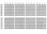
例えば、磁気ヘッド4により書き込んだ1セクタ分のユーザ・データが図4に示すように、すべてのバイトが0(ゼロ)であったものとする。なお、1セクタ中のデータ数は512バイトとしている。なお、ECCバイトの記載は省略している。
以上のユーザ・データを磁気ディスク2に書き込んだ後に、磁気ヘッド4により読み出したユーザ・データ(当初読み出しデータ)は、図5に示す通りである。つまり、下線を付した部位(ロケーション)のデータ値が、書き込みデータによるデータ値“0”と相違している。この相違部分の20バイト分だけデータが壊れている、つまりエラーとなっている。この当初読み出しデータは、ECC回路18により、エラーが発生しているものと判定される。そうすると、この当初読み出しデータと読み出されたECCバイトは、メモリ・マネージャ・ロジック19の指示により、メモリ16に記憶される。
当初読み出しデータについてエラー発生の判定がなされているため、同一のセクタが2回目の読み出し対象となる。この2回目の読み出しは、ドライブ・コントローラ・ロジック17が指示する。2回目の読み出しにより読み出されたユーザ・データを図6に示す。この2回目の読み出しデータと読み出されたECCバイトはセクタ・バッファ15に記憶される。2回目の読み出しデータにおいては、下線を付した23バイトのデータがエラーとなっている。
【0029】
データ比較ロジック20は、メモリ16に記憶された当初読み出しデータ、読み出されたECCバイトと、セクタ・バッファ15に記憶された2回目の読み出しデータ、読み出されたECCバイトとを比較する。なお、ECCバイト部分での誤りは無かったものとして以下の説明をする。図5および図6を比較すれば、189h〜19Dhのデータ値は、当初読み出しデータは、“00ACDB3436FD1D 12AFB6A32698DD53 6753A792BB21”であるのに対して、2回目の読み出しデータは、“328F992B5A1617 728E771B3C265FA7 24729DEC3689”である。つまり、当初読み出しデータと2回目の読み出しデータは、189h〜19Dhの範囲で一致せず変動している。この189h〜19Dhは、エラーが発生している箇所としてメモリ16に記憶する。そして、消失訂正を行うことで真正なデータを生成することが可能となる。消失訂正によってエラー訂正をすることができない場合には、エラー・リカバリ・オペレーションを実施する。
また、上記説明では、ユーザ・データ部分について行われているが、ECCバイト部分にエラーが発生していることもあるので、ECCバイト部分についても同様に読み出された値の比較を行うことによりエラーが発生している箇所を特定し、エラー訂正を行えば良いことになる。
【0030】
次に、本実施の形態により、同一のセクタに対して複数回データの読み出しを行って真正なデータを特定する手法について説明する。この手法は、複数回読み出したデータについて多数決を適用するものである。
なお、説明の便宜上、セクタにはあらかじめ、図7のWT dataに示すように、すべてのバイトに0(ゼロ)が書き込まれていたものとする。また、この例は、セクタについてエラー訂正不可能になったことを前提とする。
ECC回路18によりエラー訂正不可能と判定された後の1回目に読み出されたユーザ・データとパリティが、図7のRead1のように読めたとする。このデータは、ドライブ・コントロール・ロジック17、ECC回路18を経由してからメモリ・マネージャ・ロジック19によりセクタ・バッファ15に記憶される。
【0031】
2回目以降の読み出しでエラーの個数がエラー訂正可能な数以下の場合には正常に読み出しできたと判断されるが、本発明の効果を説明するため、これ以降の読み出しで発生するエラーの個数は必ず、ECC回路18におけるエラー訂正能力を超えていると仮定する。2回目の読み出しでは、図7のRead2のように、さらに3,4,5回目の読み出しでは図7のRead3〜5のように読めたとする。
以上の5回の読み出しデータにおいて、Address(アドレス)が00hのデータ値についてみると、“00”hが3回、“fb”hおよび“34”hが各々1回ずつとなっている。この場合、多数決として“00”が採用され、このセクタのアドレス00hには、“00”hが書き込まれていたものと判断し、この値を多数決後のデータとして、セクタ・バッファ15に記憶する。これと同様な操作をデータとパリティ全てについて行い、セクタ・バッファ15に記憶する。アドレス04hのように一度も同じ値のデータが読めなかったところは、例えば1回目の読み出しデータの値を選択するようにする。そして、当該アドレスに対応するロケーションは消去位置(Erasure Location)とする。以上の操作はデータ比較ロジック20で行うが、ハードウェアで行っても、ソフトウェアで行っても良い。
【0032】
次に、多数決を行った後のデータからシンドロームを再計算する。多数決後データ転送ロジック21は、セクタ・バッファ15から多数決後のデータを読み出し、ECC回路18内のシンドローム発生器182に多数決後のデータを転送し、シンドローム発生器182は多数決後のデータに対するシンドロームを生成する。
もし、シンドローム発生器182と多数決後データ転送ロジック21とクロック(Clock)が異なる場合には、多数決後データ転送ロジック21内で同期化してから、シンドローム発生器182にデータを転送する。シンドロームの生成もソフトウェアで行っても構わない。
シンドロームが生成されたら、ECC回路18内のデコーダ181と、多数決後データを決める際に取得した消去位置を使用して、消失訂正を行う。消失訂正が行われた後のデータは、ホスト・コンピュータ200に対する出力データとなる。
【0033】
以上のように、本実施の形態によれば、複数回読み出したデータから多数決を取ることによって、従来よりも高い確度の消失位置情報が得られ、また、エラー訂正符号を使用せずに真正データに修正されることもあることから、従来では不可能であったランダム・ノイズが大きい状態での読み出しが可能になる。
例えば、スクラッチのように数10バイトの長さにわたってデータが壊れている場合であっても、エラーが発生している部分とエラーが発生していない部分の境界付近の、正しく読めたり読めなかったりするデータに対してもこの手法を用いれば、エラーの個数を減らせるので、エラー訂正符号による復号の成功確率を上げることができる。
【0034】
図8〜図13は、多数決により真正なデータを特定するより具体的な例を示す。図8〜図12は、1回目〜5回目の読み出しデータを示している。各読み出し回において、エラーが発生したと判定された部位には、下線を付している。各読み出し回ごとのエラーは、6〜16バイトである。しかし、多数決を採用することにより、図13に示すように、エラーの数が2バイトまで減ることがわかる。
【0035】
次に、インタリーブ毎にエラー訂正を行う形態について、図14を参照しつつ説明する。
図14は、この形態を実行する際の機能ブロックを示している。
ECC回路18は、インタリーブ毎に復号を行う。したがって、インタリーブ毎にエラー訂正可能であったか、否か、及びエラー訂正可能な場合には、そのインタリーブ内の誤り位置および誤りの値を保持している。
図14において、第1の訂正・記憶手段22は、エラー訂正可能と判定されたインタリーブのデータを訂正して、セクタ・バッファ15に記憶する機能を有する。第2の訂正・記憶手段23は、エラー訂正が不可能と判定されたインタリーブについて、エラー・リカバリ・オペレーションを適用することによりエラー訂正を完了させ、セクタ・バッファ15に記憶する機能を有する。
セクタ・バッファ15には、あるセクタについての読み出された状態の読み出しデータ(図中、original)が記憶される。また、セクタ・バッファ15には、訂正が加えられた読み出しデータ(図中、corrected)も記憶される。
メモリ16には、エラー訂正されたインタリーブのデータが記憶される。本実施の形態では、4ウェイ・インタリーブを適用しているため、0〜3の4つの記憶領域に記憶される。
インタリーブ編集手段24は、メモリ16内に記憶されたインタリーブのデータを組み合わせてセクタ・データを生成する。ここで生成されたデータは、セクタ・バッファ15に記憶される。
【0036】
あるセクタの読み出しを行い、エラー訂正不可能であったとECC回路18により判断されたとする。その時に全てのインタリーブがエラー訂正不可能であったのか否かをECC回路18からの情報で判断する。
ECC回路18は、インタリーブ毎にデコーダ181により復号を行うのでインタリーブ毎にエラー訂正可能であったか、否か、及びエラー訂正可能な場合には、そのインタリーブ内エラー位置およびエラーの値を保持している。
次に、エラー訂正可能なインタリーブが存在した場合には、そのインタリーブをメモリ16上に記憶し、ECC回路18から得られた、そのインタリーブのエラー位置、エラーの値からエラー訂正を行い、訂正データとして保持しておく。複数のインタリーブがエラー訂正可能であった場合には、エラー訂正可能であったインタリーブ全てに対して、この操作を行う。
【0037】
次に、ECC回路18において、エラー訂正不可能と判定されたインタリーブがエラー訂正可能になるまで、従来のエラー・リカバリ・オペレーション等を行う。
従来は、このエラー・リカバリ・オペレーションで、そのセクタが1セクタの単位でエラー訂正可能な状態で読み出しできないとリカバリすることができなかった。しかし、本実施の形態では、エラー訂正不可能であったインタリーブだけに着目し、そのインタリーブがエラー訂正可能な状態で読み出しできたか否かだけを判断する。
エラー訂正が不可能であったインタリーブがエラー訂正可能になった場合にも、そのインタリーブの訂正をして、メモリ16上に記憶しておく。もし、複数のインタリーブがエラー訂正不可能であった場合には、それぞれのインタリーブがエラー訂正可能な状態になるまで、エラー・リカバリ・オペレーションを行うことになるが、その際にも、それらのインタリーブが同時にエラー訂正可能な状態でリードされなければならないわけではない。
【0038】
すべてのインタリーブが訂正された後で、インタリーブ編集手段24は、あらかじめ記憶しておいた各インタリーブのデータを1セクタ分のデータとして構成しながら、セクタ・バッファ15上に記憶し直す。これにより、従来はエラー訂正不可能であったセクタの読み出しデータの提供を可能にする。
なお、以上の場合であっても、CRCシンドロームによるデータの認証を行う。このデータの認証は、訂正がなされたインタリーブ毎に行ってもよいし、インタリーブ編集手段24によって、1セクタのデータとして編集された後に行ってもよい。どちらの方式で行うかはCRCをインタリーブ毎に生成しているか、1セクタのデータから生成しているかに依存している。このCRCは、通常ECC回路18によるエラー訂正の検出を行うために用意されており、ECCバイトの一部としてメディア上に記憶されている。ECC回路18はエラー訂正時には必ずCRCシンドロームによる認証を行う。
また、ECC回路18によって、エラー訂正が不要と判断されるインタリーブも存在する。その場合には、インタリーブ編集手段24は、訂正が不要と判断されるインタリーブも考慮して、1セクタのデータを生成することになる。
【0039】
以上の形態は、例えば、ソフト・エラー・レート(Soft Error Rate)が低くランダム・ノイズが非常に多い時には有効である。ある瞬間の読み出しと次の読み出しでエラー訂正不可能になるインタリーブが変動する可能性が高いからである。しかし、ソフト・エラー・レートが低いので1セクタがきれいにエラー訂正可能な状態で読めることはない。
このような場合に、本実施の形態では、1度でもエラー訂正可能な状態で読み出せたインタリーブを蓄積していくことによって、従来リカバリ不能であったセクタの読み出しを可能にする。つまり、インタリーブ単位のリカバリを行うことで、セクタ単位でリカバリ不能なセクタのリカバリを可能にするのである。
【0040】
また、本発明は、例えばリード/ライト・チャネル11の復号器等が隣接バイト(Symbol)の値によって影響を受けるような構造の場合には,磁気ディスク2からの読み出しを行わずに、エラー訂正可能であったインタリーブのデータを使用して再度リード/ライト・チャネル11内の復号器等で復号する。そうすることによって、エラー訂正不可能であったインタリーブの訂正を行うことも可能になる。この場合には、エラー訂正されたインタリーブのデータと誤り不可能なインタリーブのデータを1セクタの形に並び替えながら、リード/ライト・チャネル11にそのデータを転送する手段が必要になる。
【0041】
【発明の効果】
以上説明したように、本発明によれば、エラー訂正の確率を上げ、正しい読み出しデータの生成に寄与する。
【図面の簡単な説明】
【図1】 本実施の形態によるハード・ディスク・ドライブの主要構成を示すブロック図である。
【図2】 ハード・ディスク・ドライブが、読み出しデータを処理する際の機能ブロックを示す図である。
【図3】 磁気ディスクにスクラッチが生じている場合の読み出し波形を示すグラフである。
【図4】 本実施の形態により磁気ディスクに書き込んだ1セクタ分のユーザ・データを示す図である。
【図5】 本実施の形態における1回目の読み出しデータを示す図である。
【図6】 本実施の形態における2回目の読み出しデータを示す図である。
【図7】 本実施の形態において、1〜5回目のデータおよび多数決によるデータを対比して示す図である。
【図8】 本実施の形態における1回目の読み出しデータを示す図である。
【図9】 本実施の形態における2回目の読み出しデータを示す図である。
【図10】 本実施の形態における3回目の読み出しデータを示す図である。
【図11】 本実施の形態における4回目の読み出しデータを示す図である。
【図12】 本実施の形態における5回目の読み出しデータを示す図である。
【図13】 本実施の形態において、多数決によって特定された真正なデータを示す図である。
【図14】 本実施の形態において、インタリーブ毎にエラー訂正を行う際の機能ブロック図である。
【符号の説明】
1…ハード・ディスク・ドライブ、2…磁気ディスク、3…スピンドル・モータ、4…磁気ヘッド、5…アクチュエータ、6…VCM(ボイス・コイル・モータ)、7…DAC、11…リード/ライト・チャネル、12…MPU、13…HDC(ハード・ディスク・コントローラ)、14…サーボ・コントローラ、15…セクタ・バッファ、16…メモリ、17…ドライブ・コントロール・ロジック、18…ECC回路、19…メモリ・マネージャ・ロジック、20…データ比較ロジック、21…多数決後データ転送ロジック、22…第1の訂正・記憶手段、23…第2の訂正・記憶手段、24…インタリーブ編集手段、181…デコーダ、182…シンドローム発生器、200…ホスト・コンピュータ[0001]
BACKGROUND OF THE INVENTION
The present invention relates to a data storage device represented by a hard disk drive, and more particularly to determination of an error in data read from a data storage medium and further correction of error data.
[0002]
[Prior art]
A hard disk drive is one of the most popular computer external storage devices. As is well known, a magnetic disk, which is a storage medium of a hard disk drive, uses a sector obtained by further dividing a track obtained by dividing the disk surface into a tree ring shape in a radial manner as a minimum data recording unit. The linear recording density can be increased toward the outer periphery of the magnetic disk. Therefore, in the zone bit recording (Zoned Bit Recording) method, which is currently the main data recording method for magnetic disks, all tracks are grouped into several zones, and the linear recording density is constant in each zone. . Then, since the length of the sector is usually 512 bytes (bytes), the number of sectors increases as the track is closer to the outer periphery of the magnetic disk.
The hard disk drive includes a magnetic head for reading data stored in the magnetic disk or writing data to the magnetic disk. This magnetic head is mounted on an actuator mechanism that is swung by a VCM (Voice Coil Motor).
When the magnetic head reads or writes data, the magnetic head is moved and positioned to a predetermined track by driving the actuator mechanism. The magnetic head is controlled to move to a predetermined position based on servo information stored on the magnetic disk.
[0003]
In a hard disk drive, the recording density per unit area becomes very large, the S / N of the signal processing system becomes low, and the presence of magnetic defects on the magnetic disk cannot be ignored. For this reason, error correction has become important in order to increase the reliability of data read and written even if there are defects on the magnetic disk.
Error correction is performed when the read data includes an error. The error occurs due to peeling of the magnetic layer formed on the magnetic disk, scratches due to rubbing with the magnetic head, dust on the magnetic disk, or the like. In order to correct this error, the hard disk drive adds several tens of bytes of parity based on each sector of data (usually 512 bytes) on the magnetic disk. This parity is called ECC (Error Correcting Code). At the time of reading, a syndrome is generated from the data read by the ECC circuit provided in the hard disk drive and the read parity (ECC), an error position is detected from the syndrome, and error correction processing is performed. Is done.
As an example, the error correction capability is considered to be 4-way interleaving (512-byte / 1-sector data is a method in which 1-sector data is sequentially divided into four parts [interleaving] from the head and parity is obtained for each interleaving). In this case, when an ECC byte of 12 bytes / interleave, that is, 48 bytes / sector is added, an error of up to 5 bytes per interleave, that is, 20 bytes per sector can be corrected, depending on how to obtain it. Therefore, if the error in the reproduced data is within the error correction capability, the error correction can be performed without interrupting the data transfer while reading the data sequentially. This is called OTF (On The Fly Collection).
[0004]
However, if the number of bytes in error exceeds the correction capability, the MPU or HDC (Hard Disk Controller) provided in the hard disk drive will offset the read head in the track width direction. And retry reading while changing the readout parameters such as channel equalizer coefficients. This is called an error recovery operation. In the case where error correction cannot be performed even by the error recovery operation, if an error position is specified by some method, a larger amount of errors can be corrected than correction by OTF. This is called erasure correction. For detecting an error position, conventionally, as shown in, for example, Japanese Patent Laid-Open No. 2000-57707, a method of using error position information based on a parity error signal from a Viterbi Decoder of a read / write channel Etc. have been used.
[0005]
[Problems to be solved by the invention]
However, in the above method, excessive error positions are required due to variations in individual head characteristics such as the soft error rate, and in particular, random noise (Random Noise) is the cause of uncorrectable errors. In some cases, the location where an error occurs every time reading is performed. Furthermore, there is a problem that the accuracy of the error position obtained from the Viterbi decoder is uncertain. Therefore, if the error correction capability is exceeded, it can be said that even if error correction is performed, the probability of proper correction is not so high.
Accordingly, an object of the present invention is to increase the probability of error correction and generate correct read data.
[0006]
[Means for Solving the Problems]
As described above, when random noise is a factor that makes error correction impossible, the location where an error occurs varies with each reading. However, if this characteristic is used, the error occurrence position can be specified. In other words, data is read multiple times for the same sector, the read data is compared, and if the read data matches regardless of the read count, no error has occurred for the data, and the reverse If the data do not match, it is considered that an error has occurred. For example, in the case of a hard disk drive, if the value at a predetermined position in the same sector is “0” regardless of the number of readings, the data at the predetermined position can be regarded as genuine data. On the other hand, if the value at the predetermined position is “1” at the first reading, but is “0” at the second reading, the data at the predetermined position is stored. Can be considered an error.
[0007]
The present invention is based on the above knowledge, a head that performs write processing or read processing based on a write request and a read request transferred from a host, write data is stored by the head write processing, and read processing A storage medium from which read data is read out, a storage means for temporarily storing the read data read by the head a plurality of times in a predetermined area of the storage medium, and a comparison means for comparing the stored read data. A data storage device characterized by the above.
Since the data storage device of the present invention can compare the read data read a plurality of times, as described above, it can determine whether or not an error has occurred in the compared data.
[0008]
In the data storage device of the present invention, the comparison means can determine whether the data values of the corresponding portions of the stored read data match or do not match. If the data values do not match, it can be assumed that the data value has an error. On the other hand, if the data values match, no error has occurred in the data value, and the data value can be handled as authentic data.
According to the data storage device of the present invention, since an error occurrence portion can be found with high accuracy by comparing data, error correction means for correcting an error with respect to a data value of a part determined to be inconsistent by the comparison means is provided. If this is the case, the output read data will be extremely accurate.
[0009]
In the data storage device of the present invention, it is desirable that the number of times of reading is three or more in order to improve the accuracy when specifying the authentic data by comparing the read data. In that case, it is conceivable to take a majority vote for the data value of the corresponding portion of the stored read data. Then, the comparison means can regard the value read most by the majority decision as an authentic data value in the part, and can generate read data by a combination of the values of the authentic data. Conversely, data other than data regarded as genuine is considered to have an error, and this data is subject to error correction.
[0010]
The present invention provides the following read data processing device which can be used in the above data storage device. The read data processing apparatus includes a first determination unit that determines whether or not a data error has occurred with respect to the first data read in units of sectors having a predetermined capacity, and data by the first determination unit. Re-read instruction means for executing read processing again to obtain second data for the sector including the first data determined to have an error, and a first at a position corresponding to each other A second determination unit that determines whether or not the data value and the second data value have fluctuated, and an error that performs error correction on the first data and the second data that are determined to have fluctuated by the second determination unit Correction means.
The read data processing apparatus according to the present invention identifies data in which an error has occurred by determining whether or not there is a change in the value of the first data and the value of the second data at positions corresponding to each other. Then, an error correction process is performed on the identified data. Therefore, the probability of error correction can be improved.
[0011]
In the read data processing apparatus of the present invention, it is not always necessary to determine whether or not there is a change in the value of the first data and the value of the second data at positions corresponding to each other. If no error has occurred, such a determination makes little sense. Therefore, when the second determination unit determines that a data error has occurred by the first determination unit, the second data and the value of the first data at the positions corresponding to each other It is desirable to determine the presence or absence of fluctuations in the data value of 2.
[0012]
The present invention also provides the following read data processing device for processing data read in units of sectors from a storage medium on which tracks composed of a plurality of sectors are formed. The read data processing apparatus includes a storage means for temporarily storing n read data read n times (n is a natural number) for a predetermined sector, and for each of the n read data for each location in the sector. And specifying means for specifying the maximum frequency value, and read data constituting means for forming the generated data based on the maximum frequency value specified for each location by the specifying means.
The read data processing apparatus described above can regard the value of the maximum frequency specified for each location as genuine data, and perform processing such as error correction on other data to generate data for output.
[0013]
In the read data processing apparatus of the present invention, it may not be possible to specify the maximum frequency value for each location in the sector for n read data. In that case, the value of the read data read for the first time, for example, at a predetermined number of times of reading can be specified as a value constituting the generated data at the location, and can be a target of subsequent error correction processing. .
The read data processing apparatus of the present invention can include error correction means for performing error correction processing on the generated data configured by the read data configuration means.
[0014]
Currently, in a hard disk drive, data read from a magnetic disk is divided into predetermined units of interleaving as described above. Here, 4-way interleaving means that when one sector of user data is 00 01 02 03 04 05 06 ...... 511, interleave 0 has 00, 04, 08 ...., interleave 1 has 01,05,09 .... interleave 2 has 02,06,10 .... interleave 3 has 03,07,11 .... As described above, in each interleaving, only data of a location (Location) obtained by skipping four pieces of user data is used for encoding.
[0015]
In the above interleaving, it is assumed that an error that cannot be corrected by the used ECC (error correction code) occurs in one sector of data. However, when viewed in units of interleaving, there will be interleaving that can be corrected by ECC and interleaving that cannot be corrected. Therefore, by executing error correction for each interleave and combining the error-corrected interleave, it is possible to read a sector that could not be read conventionally.
The present invention also provides a data storage device based on the above viewpoint. According to the data storage device of the present invention, a write process or a read process is performed based on a write request and a read request transferred from a host, write data is stored by the write process of the head, and read data is read by the read process. A storage medium to be read; a first storage unit that divides read data read from the storage medium by the head based on a predetermined rule and temporarily stores the data for each predetermined unit; and for each predetermined unit that is divided and stored And determining means for determining whether or not an error has occurred in the read data.
[0016]
The data storage device of the present invention further includes error correction means for performing error correction processing on the read data for each predetermined unit when an error determination is made on the read data. Then, the determination unit recognizes whether or not the error correction is possible after performing the error correction process by the error correction unit for each predetermined unit that is divided and stored with respect to the read data subjected to the error determination.
Next, the data storage device of the present invention can further include second storage means for storing read data, which is recognized by the determination means as being error-correctable and has been subjected to error correction, as a predetermined unit.
On the other hand, the data storage device of the present invention performs a predetermined process that enables error correction on a predetermined unit including read data that is recognized by the determination means as being incapable of error correction. The predetermined processing enabling error correction includes an error recovery operation in which read retry is performed while changing read parameters such as an offset in the track width direction of the read head and a coefficient of a channel equalizer.
The error correction means performs error correction processing on a predetermined unit that has been subjected to predetermined processing that enables error correction, and the predetermined unit that has been subjected to error correction processing is stored in the second storage means.
Based on the read data stored in the second storage means that is recognized as being error-correctable and corrected by the error-correcting means and read-out data that is recognized as being incapable of error correction and corrected by the error-correcting means Thus, an editing means for generating a predetermined unit to be output to the host can be provided.
[0017]
The present invention provides the following read data processing apparatus which can be applied to the above data storage device. This processing device is a read data processing device that processes data read from a storage medium in units of sectors into a plurality of interleaves, and includes a storage means for storing data for each interleave, and an error occurrence for each interleave. The basic configuration includes an error determination unit that determines presence / absence and an error correction unit that performs an error correction process for each interleave. The read data processing apparatus constitutes the read data to be output to the outside by a combination of interleaves in which it is determined that an error has occurred by the error determination means and the error has been corrected by the error correction means. It is a feature.
[0018]
The data storage device and the read data processing device have been described above for specifying error data or authentic data. The present invention provides the following read data processing method applicable to the data storage device and the read data processing device.
According to the present invention, user data is read from a storage medium in units of sectors, whether or not an error has occurred in user data is determined, and a sector including user data that has been determined to have an error is further detected once or twice. The user data is read again as a reading target. Then, the data value existing in the same location is compared between the user data read out initially and the user data read out again.
In this comparison, it is determined whether or not the data value fluctuates at every reading. If the data value fluctuates, the fluctuating data can be recognized as an error occurrence factor. On the other hand, if the data value does not fluctuate, the data that has not fluctuated is recognized as having no error. Here, even when all the data do not match, the data value with the highest frequency of the matched data value can be handled as a genuine data value.
[0019]
The present invention also provides the following read data processing method applicable to a data storage device related to interleaving and a read data processing device.
The present invention reads user data from a storage medium in units of sectors, classifies the read user data into a plurality of interleaves, determines whether an error has occurred in the user data for each interleave, A first error correction process is performed for each interleave determined to have occurred, and a second error correction different from the first error correction process is performed for an interleave whose error has not been corrected by the first error correction process. A read data processing method characterized by performing processing. In this read data processing method, interleaving in which it is determined that no error has occurred, interleaving in which error correction has been performed by the first error correction processing, and interleaving in which error correction has been performed by the second error correction processing, or A combination of two or more constitutes read data for one sector as an output.
[0020]
DETAILED DESCRIPTION OF THE INVENTION
Hereinafter, the present invention will be described more specifically based on embodiments.
FIG. 1 is a block diagram showing a main part of a hard disk drive 1 according to the present embodiment. In the hard disk drive 1, the
[0021]
The
[0022]
Two
The read /
The
[0023]
The
[0024]
The HDC (hard disk controller) 13 has a function as an interface of the hard disk drive 1. One of the functions is a function of receiving the write data transferred from the
The write data temporarily stored in the
[0025]
The
The
The
The
[0026]
FIG. 2 is a diagram showing functional blocks when the hard disk drive 1 processes read data.
In FIG. 2, the
The
A
The
As will be described in detail later, a
[0027]
Now, FIG. 3 shows a read waveform when a read error occurs because the
[0028]
For example, it is assumed that the user data for one sector written by the
FIG. 5 shows user data (initial read data) read by the
Since the occurrence of an error is determined for the initially read data, the same sector is the second read target. This second reading is instructed by the
[0029]
The
In the above description, the process is performed for the user data part. However, since an error may occur in the ECC byte part, the read value is similarly compared for the ECC byte part. It is only necessary to identify the location where the error has occurred and correct the error.
[0030]
Next, a method for specifying authentic data by reading data a plurality of times from the same sector according to the present embodiment will be described. This method applies a majority vote to data read a plurality of times.
For convenience of explanation, it is assumed that 0 (zero) is written in all bytes in advance in the sector as shown in WT data in FIG. This example is based on the premise that error correction is impossible for a sector.
Assume that the user data and parity read for the first time after the
[0031]
When the number of errors in the second and subsequent readings is equal to or less than the number that can be corrected, it is determined that the data has been read normally. However, in order to explain the effect of the present invention, the number of errors that occur in subsequent readings is It is assumed that the error correction capability of the
In the read data of the above five times, regarding the data value where Address is 00h, “00” h is three times, and “fb” h and “34” h are once each. In this case, “00” is adopted as the majority decision, and it is determined that “00” h is written in the address 00h of this sector, and this value is stored in the
[0032]
Next, the syndrome is recalculated from the data after the majority vote. The post-voting
If the
When the syndrome is generated, erasure correction is performed using the
[0033]
As described above, according to the present embodiment, erasure position information with higher accuracy than before can be obtained by taking a majority decision from data read a plurality of times, and authentic data without using an error correction code. Therefore, it is possible to read in a state in which random noise is large, which was impossible in the past.
For example, even if the data is broken for a length of several tens of bytes like a scratch, it can be read or cannot be read correctly near the boundary between the part where the error has occurred and the part where the error has not occurred. If this method is also used for data to be processed, the number of errors can be reduced, so that the probability of success in decoding using an error correction code can be increased.
[0034]
8 to 13 show more specific examples of specifying genuine data by majority vote. 8 to 12 show the first to fifth read data. In each reading time, the portion where it is determined that an error has occurred is underlined. The error for each read time is 6 to 16 bytes. However, by adopting the majority vote, it can be seen that the number of errors is reduced to 2 bytes as shown in FIG.
[0035]
Next, an embodiment in which error correction is performed for each interleave will be described with reference to FIG.
FIG. 14 shows functional blocks when executing this mode.
The
In FIG. 14, the first correction / storage means 22 has a function of correcting interleaved data determined to be error-correctable and storing it in the
The
The
The
[0036]
It is assumed that a certain sector is read and the
Since the
Next, when there is an error-correctable interleave, the interleave is stored in the
[0037]
Next, the conventional error recovery operation or the like is performed in the
Conventionally, in this error recovery operation, if the sector cannot be read in a state where error correction is possible in units of one sector, recovery cannot be performed. However, in this embodiment, attention is paid only to interleaving where error correction is impossible, and it is determined only whether or not the interleaving has been read out in a state where error correction is possible.
Even when interleaving, which cannot be corrected, becomes error-correctable, the interleaving is corrected and stored in the
[0038]
After all the interleaving has been corrected, the interleave editing means 24 stores the data of each interleave stored in advance on the
Even in the above case, authentication of data by CRC syndrome is performed. This data authentication may be performed for each interleave that has been corrected, or may be performed after being edited as data of one sector by the interleave editing means 24. Which method is used depends on whether a CRC is generated for each interleave or generated from data of one sector. This CRC is usually prepared for detecting error correction by the
There is also interleaving that is determined by the
[0039]
The above configuration is effective when, for example, the soft error rate is low and the random noise is very large. This is because there is a high possibility that the interleaving that makes error correction impossible at one moment reading and the next reading fluctuates. However, since the soft error rate is low, one sector cannot be read in a state where the error can be corrected accurately.
In such a case, according to the present embodiment, the sector that has been unrecoverable can be read by accumulating the interleaves that can be read even in a state where error correction is possible. That is, by performing recovery in units of interleaves, it is possible to recover sectors that cannot be recovered in units of sectors.
[0040]
In the present invention, for example, when the decoder of the read /
[0041]
【The invention's effect】
As described above, according to the present invention, the probability of error correction is increased, which contributes to the generation of correct read data.
[Brief description of the drawings]
FIG. 1 is a block diagram showing a main configuration of a hard disk drive according to an embodiment.
FIG. 2 is a diagram showing functional blocks when a hard disk drive processes read data.
FIG. 3 is a graph showing a read waveform when a scratch is generated on a magnetic disk.
FIG. 4 is a diagram showing user data for one sector written on a magnetic disk according to the present embodiment.
FIG. 5 is a diagram showing first read data in the present embodiment.
FIG. 6 is a diagram showing read data for the second time in the present embodiment.
FIG. 7 is a diagram showing, in comparison with the first to fifth data and the data by majority decision, in the present embodiment.
FIG. 8 is a diagram showing first read data in the present embodiment.
FIG. 9 is a diagram showing second read data in the present embodiment.
FIG. 10 is a diagram showing read data for the third time in the present embodiment.
FIG. 11 is a diagram showing read data for the fourth time in the present embodiment.
FIG. 12 is a diagram showing read data for the fifth time in the present embodiment.
FIG. 13 is a diagram showing authentic data specified by majority vote in the present embodiment.
FIG. 14 is a functional block diagram when error correction is performed for each interleave in the present embodiment.
[Explanation of symbols]
DESCRIPTION OF SYMBOLS 1 ... Hard disk drive, 2 ... Magnetic disk, 3 ... Spindle motor, 4 ... Magnetic head, 5 ... Actuator, 6 ... VCM (voice coil motor), 7 ... DAC, 11 ... Read / write channel , 12 ... MPU, 13 ... HDC (hard disk controller), 14 ... servo controller, 15 ... sector buffer, 16 ... memory, 17 ... drive control logic, 18 ... ECC circuit, 19 ... memory manager Logic 20: Data comparison logic 21: Data transfer logic after majority decision, 22: First correction / storage means, 23: Second correction / storage means, 24: Interleave editing means, 181: Decoder, 182:
Claims (6)
前記ヘッドの前記書き込み処理によって書き込みデータが記憶され、かつ前記読み出し処理によって読み出しデータが読み出される記憶媒体と、
前記ヘッドが前記記憶媒体の所定領域において複数回読み出した読み出しデータを一時的に各々記憶する記憶手段と、
各々記憶された前記読み出しデータの対応する部位のデータ値について多数決を取る比較手段と、
を備えることを特徴とするデータ記憶装置。A head that performs a write process or a read process based on a write request and a read request transferred from the host;
A storage medium in which write data is stored by the write process of the head and read data is read by the read process;
Storage means for temporarily storing read data read by the head a plurality of times in a predetermined area of the storage medium;
A comparison means for taking a majority vote for the data value of the corresponding portion of each of the stored read data;
A data storage device comprising:
前記多数決により最も多く読めた値を前記部位における真正なデータ値とみなし、かつ前記真正なデータ値の組み合わせによる読み出しデータを生成し、
前記エラー訂正手段は、
前記組み合わせによる読み出しデータに対してエラー訂正を行なうことを特徴とする
請求項1に記載のデータ記憶装置。The comparison means includes
The value most read by the majority is regarded as an authentic data value in the part, and read data is generated by a combination of the authentic data values,
The error correction means includes
The data storage device according to claim 1, wherein error correction is performed on read data by the combination.
所定のセクタについてn回だけ(nは2以上の自然数)読み出したn個の前記読み出しデータを一時的に記憶する記憶手段と、
n個の前記読み出しデータについて、前記セクタ内のロケーション毎に最大頻度の値を特定する特定手段と、
前記特定手段によって前記ロケーション毎に特定された前記最大頻度の値による生成データを構成する読み出しデータ構成手段と、
を備えることを特徴とする読み出しデータの処理装置。A read data processing device for processing data read in units of sectors from a storage medium on which tracks composed of a plurality of sectors are formed,
Storage means for temporarily storing the n pieces of read data read out n times (n is a natural number of 2 or more) for a predetermined sector;
a means for specifying a maximum frequency value for each location in the sector for the n read data;
Read data composing means for constructing generated data according to the value of the maximum frequency specified for each location by the specifying means;
A device for processing read data, comprising:
n個の前記読み出しデータについて、前記セクタ内のロケーション毎に最大頻度の値を特定することができない場合に、所定の読み出し回数時に読み出された前記読み出しデータの値を、当該ロケーションにおける前記生成データを構成する値として特定することを特徴とする
請求項3に記載の読み出しデータの処理装置。The specifying means is:
When the maximum frequency value cannot be specified for each location in the sector for the n pieces of read data, the value of the read data read at a predetermined number of times of reading is used as the generated data at the location. The read data processing device according to claim 3, wherein the read data processing device is specified as a value that constitutes.
請求項4に記載の読み出しデータの処理装置。5. The read data processing apparatus according to claim 4, further comprising error correction means for performing error correction processing on the generated data constituted by the read data constituting means.
前記ユーザ・データについてのエラー発生有・無を判定し、
エラー発生有と判定された前記ユーザ・データを含む前記セクタをさらに1または2回以上読み出し対象として前記ユーザ・データを再度読み出し、
当初に読み出された前記ユーザ・データと再度読み出された前記ユーザ・データについて、同一のロケーションに存在するデータ値を比較するにあたって、一致したデータ値の頻度がもっとも高い当該データ値を真正なデータ値として取り扱うことを特徴とする
読み出しデータの処理方法。Read user data from the storage medium in units of sectors,
Determine whether an error has occurred for the user data,
The sector including the user data determined to have an error has been read one or more times, and the user data is read again.
When comparing the data value existing at the same location with respect to the user data read out at the beginning and the user data read out again, the data value with the highest frequency of the matched data value is determined to be authentic. A method of processing read data, wherein the read data is handled as a data value.
Priority Applications (2)
| Application Number | Priority Date | Filing Date | Title |
|---|---|---|---|
| JP2001325696A JP3663377B2 (en) | 2001-10-23 | 2001-10-23 | Data storage device, read data processing device, and read data processing method |
| US10/279,305 US6981205B2 (en) | 2001-10-23 | 2002-10-23 | Data storage apparatus, read data processor, and read data processing method |
Applications Claiming Priority (1)
| Application Number | Priority Date | Filing Date | Title |
|---|---|---|---|
| JP2001325696A JP3663377B2 (en) | 2001-10-23 | 2001-10-23 | Data storage device, read data processing device, and read data processing method |
Publications (2)
| Publication Number | Publication Date |
|---|---|
| JP2003141822A JP2003141822A (en) | 2003-05-16 |
| JP3663377B2 true JP3663377B2 (en) | 2005-06-22 |
Family
ID=19142208
Family Applications (1)
| Application Number | Title | Priority Date | Filing Date |
|---|---|---|---|
| JP2001325696A Expired - Fee Related JP3663377B2 (en) | 2001-10-23 | 2001-10-23 | Data storage device, read data processing device, and read data processing method |
Country Status (2)
| Country | Link |
|---|---|
| US (1) | US6981205B2 (en) |
| JP (1) | JP3663377B2 (en) |
Families Citing this family (95)
| Publication number | Priority date | Publication date | Assignee | Title |
|---|---|---|---|---|
| JP2003346432A (en) * | 2002-05-22 | 2003-12-05 | Internatl Business Mach Corp <Ibm> | Data storage device and data processing method |
| JP2004234545A (en) * | 2003-01-31 | 2004-08-19 | Toshiba Corp | Control circuit and memory controller |
| JP3972911B2 (en) * | 2004-02-24 | 2007-09-05 | ソニー株式会社 | Data processing apparatus and method, and reproducing apparatus and method |
| JP4007331B2 (en) * | 2004-02-24 | 2007-11-14 | ソニー株式会社 | Playback apparatus and method |
| US7213192B2 (en) * | 2004-09-08 | 2007-05-01 | Fujitsu Limited | Methods and apparatus for correcting errors in data read from a disk drive |
| JP4761910B2 (en) * | 2005-10-05 | 2011-08-31 | 株式会社東芝 | Nonvolatile semiconductor memory device and nonvolatile memory system using the same |
| US7634706B1 (en) * | 2005-11-22 | 2009-12-15 | Seagate Technology Llc | Majority-detected erasure enhanced error correction |
| US8738841B2 (en) | 2007-12-27 | 2014-05-27 | Sandisk Enterprise IP LLC. | Flash memory controller and system including data pipelines incorporating multiple buffers |
| US7885028B2 (en) * | 2008-04-08 | 2011-02-08 | Samsung Electronics Co., Ltd. | Data error recovery using voting on multiple retrials |
| JP2010092561A (en) * | 2008-10-10 | 2010-04-22 | Toshiba Storage Device Corp | Storage device data reading method and storage device |
| US8086944B2 (en) * | 2009-06-29 | 2011-12-27 | Samsung Electronics Co., Ltd. | Hard disk drive with data error recovery using multiple reads and derived reliability information |
| JP4660612B2 (en) * | 2009-07-09 | 2011-03-30 | 株式会社東芝 | Information reproducing apparatus and information reproducing method |
| US8365041B2 (en) | 2010-03-17 | 2013-01-29 | Sandisk Enterprise Ip Llc | MLC self-raid flash data protection scheme |
| US8484529B2 (en) | 2010-06-24 | 2013-07-09 | International Business Machines Corporation | Error correction and detection in a redundant memory system |
| US8898511B2 (en) | 2010-06-24 | 2014-11-25 | International Business Machines Corporation | Homogeneous recovery in a redundant memory system |
| US8631271B2 (en) | 2010-06-24 | 2014-01-14 | International Business Machines Corporation | Heterogeneous recovery in a redundant memory system |
| US8549378B2 (en) | 2010-06-24 | 2013-10-01 | International Business Machines Corporation | RAIM system using decoding of virtual ECC |
| US8522122B2 (en) * | 2011-01-29 | 2013-08-27 | International Business Machines Corporation | Correcting memory device and memory channel failures in the presence of known memory device failures |
| US8909982B2 (en) | 2011-06-19 | 2014-12-09 | Sandisk Enterprise Ip Llc | System and method for detecting copyback programming problems |
| US8910020B2 (en) | 2011-06-19 | 2014-12-09 | Sandisk Enterprise Ip Llc | Intelligent bit recovery for flash memory |
| WO2013021588A1 (en) | 2011-08-09 | 2013-02-14 | パナソニック株式会社 | Decoding device and decoding method |
| US8793543B2 (en) | 2011-11-07 | 2014-07-29 | Sandisk Enterprise Ip Llc | Adaptive read comparison signal generation for memory systems |
| US8924815B2 (en) | 2011-11-18 | 2014-12-30 | Sandisk Enterprise Ip Llc | Systems, methods and devices for decoding codewords having multiple parity segments |
| US9048876B2 (en) | 2011-11-18 | 2015-06-02 | Sandisk Enterprise Ip Llc | Systems, methods and devices for multi-tiered error correction |
| US8954822B2 (en) | 2011-11-18 | 2015-02-10 | Sandisk Enterprise Ip Llc | Data encoder and decoder using memory-specific parity-check matrix |
| US9699263B1 (en) | 2012-08-17 | 2017-07-04 | Sandisk Technologies Llc. | Automatic read and write acceleration of data accessed by virtual machines |
| US9501398B2 (en) | 2012-12-26 | 2016-11-22 | Sandisk Technologies Llc | Persistent storage device with NVRAM for staging writes |
| US9612948B2 (en) | 2012-12-27 | 2017-04-04 | Sandisk Technologies Llc | Reads and writes between a contiguous data block and noncontiguous sets of logical address blocks in a persistent storage device |
| US9239751B1 (en) | 2012-12-27 | 2016-01-19 | Sandisk Enterprise Ip Llc | Compressing data from multiple reads for error control management in memory systems |
| US9454420B1 (en) | 2012-12-31 | 2016-09-27 | Sandisk Technologies Llc | Method and system of reading threshold voltage equalization |
| US9003264B1 (en) | 2012-12-31 | 2015-04-07 | Sandisk Enterprise Ip Llc | Systems, methods, and devices for multi-dimensional flash RAID data protection |
| US9329928B2 (en) | 2013-02-20 | 2016-05-03 | Sandisk Enterprise IP LLC. | Bandwidth optimization in a non-volatile memory system |
| US9214965B2 (en) | 2013-02-20 | 2015-12-15 | Sandisk Enterprise Ip Llc | Method and system for improving data integrity in non-volatile storage |
| US9870830B1 (en) | 2013-03-14 | 2018-01-16 | Sandisk Technologies Llc | Optimal multilevel sensing for reading data from a storage medium |
| US9092350B1 (en) | 2013-03-15 | 2015-07-28 | Sandisk Enterprise Ip Llc | Detection and handling of unbalanced errors in interleaved codewords |
| US9136877B1 (en) | 2013-03-15 | 2015-09-15 | Sandisk Enterprise Ip Llc | Syndrome layered decoding for LDPC codes |
| US9236886B1 (en) | 2013-03-15 | 2016-01-12 | Sandisk Enterprise Ip Llc | Universal and reconfigurable QC-LDPC encoder |
| US9367246B2 (en) | 2013-03-15 | 2016-06-14 | Sandisk Technologies Inc. | Performance optimization of data transfer for soft information generation |
| US9244763B1 (en) | 2013-03-15 | 2016-01-26 | Sandisk Enterprise Ip Llc | System and method for updating a reading threshold voltage based on symbol transition information |
| US9009576B1 (en) | 2013-03-15 | 2015-04-14 | Sandisk Enterprise Ip Llc | Adaptive LLR based on syndrome weight |
| US10049037B2 (en) | 2013-04-05 | 2018-08-14 | Sandisk Enterprise Ip Llc | Data management in a storage system |
| US9170941B2 (en) | 2013-04-05 | 2015-10-27 | Sandisk Enterprises IP LLC | Data hardening in a storage system |
| US9159437B2 (en) | 2013-06-11 | 2015-10-13 | Sandisk Enterprise IP LLC. | Device and method for resolving an LM flag issue |
| US9384126B1 (en) | 2013-07-25 | 2016-07-05 | Sandisk Technologies Inc. | Methods and systems to avoid false negative results in bloom filters implemented in non-volatile data storage systems |
| US9524235B1 (en) | 2013-07-25 | 2016-12-20 | Sandisk Technologies Llc | Local hash value generation in non-volatile data storage systems |
| US9043517B1 (en) | 2013-07-25 | 2015-05-26 | Sandisk Enterprise Ip Llc | Multipass programming in buffers implemented in non-volatile data storage systems |
| US9361221B1 (en) | 2013-08-26 | 2016-06-07 | Sandisk Technologies Inc. | Write amplification reduction through reliable writes during garbage collection |
| US9639463B1 (en) | 2013-08-26 | 2017-05-02 | Sandisk Technologies Llc | Heuristic aware garbage collection scheme in storage systems |
| US9442670B2 (en) | 2013-09-03 | 2016-09-13 | Sandisk Technologies Llc | Method and system for rebalancing data stored in flash memory devices |
| US9519577B2 (en) | 2013-09-03 | 2016-12-13 | Sandisk Technologies Llc | Method and system for migrating data between flash memory devices |
| US9158349B2 (en) | 2013-10-04 | 2015-10-13 | Sandisk Enterprise Ip Llc | System and method for heat dissipation |
| US9323637B2 (en) | 2013-10-07 | 2016-04-26 | Sandisk Enterprise Ip Llc | Power sequencing and data hardening architecture |
| US9442662B2 (en) | 2013-10-18 | 2016-09-13 | Sandisk Technologies Llc | Device and method for managing die groups |
| US9298608B2 (en) | 2013-10-18 | 2016-03-29 | Sandisk Enterprise Ip Llc | Biasing for wear leveling in storage systems |
| US9436831B2 (en) | 2013-10-30 | 2016-09-06 | Sandisk Technologies Llc | Secure erase in a memory device |
| US9263156B2 (en) | 2013-11-07 | 2016-02-16 | Sandisk Enterprise Ip Llc | System and method for adjusting trip points within a storage device |
| US9244785B2 (en) | 2013-11-13 | 2016-01-26 | Sandisk Enterprise Ip Llc | Simulated power failure and data hardening |
| US9152555B2 (en) | 2013-11-15 | 2015-10-06 | Sandisk Enterprise IP LLC. | Data management with modular erase in a data storage system |
| US9703816B2 (en) | 2013-11-19 | 2017-07-11 | Sandisk Technologies Llc | Method and system for forward reference logging in a persistent datastore |
| US9520197B2 (en) | 2013-11-22 | 2016-12-13 | Sandisk Technologies Llc | Adaptive erase of a storage device |
| US9520162B2 (en) | 2013-11-27 | 2016-12-13 | Sandisk Technologies Llc | DIMM device controller supervisor |
| US9280429B2 (en) | 2013-11-27 | 2016-03-08 | Sandisk Enterprise Ip Llc | Power fail latching based on monitoring multiple power supply voltages in a storage device |
| US9122636B2 (en) | 2013-11-27 | 2015-09-01 | Sandisk Enterprise Ip Llc | Hard power fail architecture |
| US9582058B2 (en) | 2013-11-29 | 2017-02-28 | Sandisk Technologies Llc | Power inrush management of storage devices |
| US9250676B2 (en) | 2013-11-29 | 2016-02-02 | Sandisk Enterprise Ip Llc | Power failure architecture and verification |
| US9092370B2 (en) | 2013-12-03 | 2015-07-28 | Sandisk Enterprise Ip Llc | Power failure tolerant cryptographic erase |
| US9235245B2 (en) | 2013-12-04 | 2016-01-12 | Sandisk Enterprise Ip Llc | Startup performance and power isolation |
| US9129665B2 (en) | 2013-12-17 | 2015-09-08 | Sandisk Enterprise Ip Llc | Dynamic brownout adjustment in a storage device |
| US9549457B2 (en) | 2014-02-12 | 2017-01-17 | Sandisk Technologies Llc | System and method for redirecting airflow across an electronic assembly |
| US9497889B2 (en) | 2014-02-27 | 2016-11-15 | Sandisk Technologies Llc | Heat dissipation for substrate assemblies |
| US9703636B2 (en) | 2014-03-01 | 2017-07-11 | Sandisk Technologies Llc | Firmware reversion trigger and control |
| US9485851B2 (en) | 2014-03-14 | 2016-11-01 | Sandisk Technologies Llc | Thermal tube assembly structures |
| US9348377B2 (en) | 2014-03-14 | 2016-05-24 | Sandisk Enterprise Ip Llc | Thermal isolation techniques |
| US9519319B2 (en) | 2014-03-14 | 2016-12-13 | Sandisk Technologies Llc | Self-supporting thermal tube structure for electronic assemblies |
| US9448876B2 (en) | 2014-03-19 | 2016-09-20 | Sandisk Technologies Llc | Fault detection and prediction in storage devices |
| US9454448B2 (en) | 2014-03-19 | 2016-09-27 | Sandisk Technologies Llc | Fault testing in storage devices |
| US9390814B2 (en) | 2014-03-19 | 2016-07-12 | Sandisk Technologies Llc | Fault detection and prediction for data storage elements |
| US9626400B2 (en) | 2014-03-31 | 2017-04-18 | Sandisk Technologies Llc | Compaction of information in tiered data structure |
| US9626399B2 (en) | 2014-03-31 | 2017-04-18 | Sandisk Technologies Llc | Conditional updates for reducing frequency of data modification operations |
| US9390021B2 (en) | 2014-03-31 | 2016-07-12 | Sandisk Technologies Llc | Efficient cache utilization in a tiered data structure |
| US9697267B2 (en) | 2014-04-03 | 2017-07-04 | Sandisk Technologies Llc | Methods and systems for performing efficient snapshots in tiered data structures |
| US10372613B2 (en) | 2014-05-30 | 2019-08-06 | Sandisk Technologies Llc | Using sub-region I/O history to cache repeatedly accessed sub-regions in a non-volatile storage device |
| US10656842B2 (en) | 2014-05-30 | 2020-05-19 | Sandisk Technologies Llc | Using history of I/O sizes and I/O sequences to trigger coalesced writes in a non-volatile storage device |
| US10656840B2 (en) | 2014-05-30 | 2020-05-19 | Sandisk Technologies Llc | Real-time I/O pattern recognition to enhance performance and endurance of a storage device |
| US9070481B1 (en) | 2014-05-30 | 2015-06-30 | Sandisk Technologies Inc. | Internal current measurement for age measurements |
| US9703491B2 (en) | 2014-05-30 | 2017-07-11 | Sandisk Technologies Llc | Using history of unaligned writes to cache data and avoid read-modify-writes in a non-volatile storage device |
| US10114557B2 (en) | 2014-05-30 | 2018-10-30 | Sandisk Technologies Llc | Identification of hot regions to enhance performance and endurance of a non-volatile storage device |
| US9093160B1 (en) | 2014-05-30 | 2015-07-28 | Sandisk Technologies Inc. | Methods and systems for staggered memory operations |
| US10162748B2 (en) | 2014-05-30 | 2018-12-25 | Sandisk Technologies Llc | Prioritizing garbage collection and block allocation based on I/O history for logical address regions |
| US8891303B1 (en) | 2014-05-30 | 2014-11-18 | Sandisk Technologies Inc. | Method and system for dynamic word line based configuration of a three-dimensional memory device |
| US9645749B2 (en) | 2014-05-30 | 2017-05-09 | Sandisk Technologies Llc | Method and system for recharacterizing the storage density of a memory device or a portion thereof |
| US10146448B2 (en) | 2014-05-30 | 2018-12-04 | Sandisk Technologies Llc | Using history of I/O sequences to trigger cached read ahead in a non-volatile storage device |
| US9652381B2 (en) | 2014-06-19 | 2017-05-16 | Sandisk Technologies Llc | Sub-block garbage collection |
| US9443601B2 (en) | 2014-09-08 | 2016-09-13 | Sandisk Technologies Llc | Holdup capacitor energy harvesting |
| US10205562B1 (en) * | 2017-01-03 | 2019-02-12 | Mbit Wireless, Inc. | Method and apparatus for error correction |
Family Cites Families (8)
| Publication number | Priority date | Publication date | Assignee | Title |
|---|---|---|---|---|
| JPS5487514A (en) | 1977-12-23 | 1979-07-12 | Nec Corp | Magnetic disc apparatus |
| US4564945A (en) * | 1983-06-20 | 1986-01-14 | Reference Technology, Inc. | Error-correction code for digital data on video disc |
| JP2605272B2 (en) | 1987-02-20 | 1997-04-30 | ソニー株式会社 | Error correction decoding method |
| JPH0973738A (en) * | 1995-06-30 | 1997-03-18 | Sony Corp | Recording device |
| JP2000182292A (en) * | 1998-12-15 | 2000-06-30 | Fujitsu Ltd | Optical storage device and recording / reproducing method for optical storage medium |
| US6606210B1 (en) * | 1999-04-21 | 2003-08-12 | Seagate Technology Llc | Intelligent sector recovery algorithm |
| US6389573B1 (en) | 1999-06-29 | 2002-05-14 | Maxtor Corporation | Enhanced read retrial scheme |
| JP2001023317A (en) * | 1999-07-02 | 2001-01-26 | Nec Corp | Optical disk recording and reproducing method, device therefor and medium storing optical disk recording and reproducing program |
-
2001
- 2001-10-23 JP JP2001325696A patent/JP3663377B2/en not_active Expired - Fee Related
-
2002
- 2002-10-23 US US10/279,305 patent/US6981205B2/en not_active Expired - Lifetime
Also Published As
| Publication number | Publication date |
|---|---|
| US20030112669A1 (en) | 2003-06-19 |
| JP2003141822A (en) | 2003-05-16 |
| US6981205B2 (en) | 2005-12-27 |
Similar Documents
| Publication | Publication Date | Title |
|---|---|---|
| JP3663377B2 (en) | Data storage device, read data processing device, and read data processing method | |
| US6661591B1 (en) | Disk drive employing sector-reconstruction-interleave sectors each storing redundancy data generated in response to an interleave of data sectors | |
| US7800853B1 (en) | Correcting servo sectors in a disk drive | |
| US7027256B1 (en) | Disk drive having servo sectors that store repeatable runout correction values and related error correction code data | |
| US7191382B2 (en) | Methods and apparatus for correcting data and error detection codes on the fly | |
| US6687850B1 (en) | Disk drive for storing sector-reconstruction sectors and for storing a sector-reconstruction status in sectors distributed around a disk | |
| US6181497B1 (en) | System and method for providing nonadjacent redundancy synchronization bytes | |
| US7107510B2 (en) | Data storage device and data processing method | |
| JPH04219677A (en) | Method of recovering data | |
| CN1314046C (en) | Appts. and method with checking and erasing and correcting functions | |
| KR20080095308A (en) | A recording medium, a recording and reproducing apparatus, a reproducing controller, a reproducing control method, and a reproducing control program | |
| US6288861B1 (en) | Disk drive with sector numbers encoded by sequences of sector types | |
| US20050060630A1 (en) | Direct partial update of CRC/ECC check bytes | |
| US20200081779A1 (en) | Magnetic disk device and data read method thereof | |
| US5889796A (en) | Method of insuring data integrity with a data randomizer | |
| Jaquette | LTO: A better format for mid-range tape | |
| US7941729B2 (en) | Data storage device and error processing method in its read processing | |
| US7131052B2 (en) | Algebraic decoder and method for correcting an arbitrary mixture of burst and random errors | |
| US6587977B1 (en) | o,k,m,/m recording code | |
| US7322003B2 (en) | Information storage device | |
| US9633691B2 (en) | Storage controller, storage device, and method | |
| US20070198904A1 (en) | Error correction processing apparatus and error correction processing method | |
| JP5073052B2 (en) | Error correction circuit and disk storage device | |
| JPH0620403A (en) | Magnetic disk unit | |
| US12347454B1 (en) | High-density archival storage using conventional hard disk drive architecture |
Legal Events
| Date | Code | Title | Description |
|---|---|---|---|
| A131 | Notification of reasons for refusal |
Free format text: JAPANESE INTERMEDIATE CODE: A131 Effective date: 20040615 |
|
| RD14 | Notification of resignation of power of sub attorney |
Free format text: JAPANESE INTERMEDIATE CODE: A7434 Effective date: 20040617 |
|
| A521 | Written amendment |
Free format text: JAPANESE INTERMEDIATE CODE: A523 Effective date: 20040830 |
|
| TRDD | Decision of grant or rejection written | ||
| A01 | Written decision to grant a patent or to grant a registration (utility model) |
Free format text: JAPANESE INTERMEDIATE CODE: A01 Effective date: 20050322 |
|
| A61 | First payment of annual fees (during grant procedure) |
Free format text: JAPANESE INTERMEDIATE CODE: A61 Effective date: 20050328 |
|
| R150 | Certificate of patent or registration of utility model |
Free format text: JAPANESE INTERMEDIATE CODE: R150 |
|
| S111 | Request for change of ownership or part of ownership |
Free format text: JAPANESE INTERMEDIATE CODE: R313113 |
|
| R360 | Written notification for declining of transfer of rights |
Free format text: JAPANESE INTERMEDIATE CODE: R360 |
|
| R370 | Written measure of declining of transfer procedure |
Free format text: JAPANESE INTERMEDIATE CODE: R370 |
|
| LAPS | Cancellation because of no payment of annual fees |