JP3663090B2 - Gas circuit breaker and gas insulated switchgear provided with the same - Google Patents
Gas circuit breaker and gas insulated switchgear provided with the same Download PDFInfo
- Publication number
- JP3663090B2 JP3663090B2 JP29259399A JP29259399A JP3663090B2 JP 3663090 B2 JP3663090 B2 JP 3663090B2 JP 29259399 A JP29259399 A JP 29259399A JP 29259399 A JP29259399 A JP 29259399A JP 3663090 B2 JP3663090 B2 JP 3663090B2
- Authority
- JP
- Japan
- Prior art keywords
- circuit breaker
- container
- main
- movable contact
- gas
- Prior art date
- Legal status (The legal status is an assumption and is not a legal conclusion. Google has not performed a legal analysis and makes no representation as to the accuracy of the status listed.)
- Expired - Fee Related
Links
Images


Classifications
-
- H—ELECTRICITY
- H01—ELECTRIC ELEMENTS
- H01H—ELECTRIC SWITCHES; RELAYS; SELECTORS; EMERGENCY PROTECTIVE DEVICES
- H01H33/00—High-tension or heavy-current switches with arc-extinguishing or arc-preventing means
- H01H33/02—Details
- H01H33/42—Driving mechanisms
-
- H—ELECTRICITY
- H01—ELECTRIC ELEMENTS
- H01H—ELECTRIC SWITCHES; RELAYS; SELECTORS; EMERGENCY PROTECTIVE DEVICES
- H01H3/00—Mechanisms for operating contacts
- H01H3/02—Operating parts, i.e. for operating driving mechanism by a mechanical force external to the switch
- H01H3/08—Turn knobs
- H01H3/10—Means for securing to shaft of driving mechanism
- H01H2003/105—Means for securing to shaft of driving mechanism with compensation of misalignment in the link between the operating part, the driving mechanism and the switch, e.g. misalignment between two axis
-
- H—ELECTRICITY
- H01—ELECTRIC ELEMENTS
- H01H—ELECTRIC SWITCHES; RELAYS; SELECTORS; EMERGENCY PROTECTIVE DEVICES
- H01H33/00—High-tension or heavy-current switches with arc-extinguishing or arc-preventing means
- H01H33/02—Details
- H01H33/53—Cases; Reservoirs, tanks, piping or valves, for arc-extinguishing fluid; Accessories therefor, e.g. safety arrangements, pressure relief devices
- H01H33/56—Gas reservoirs
- H01H33/565—Gas-tight sealings for moving parts penetrating into the reservoir
Landscapes
- Driving Mechanisms And Operating Circuits Of Arc-Extinguishing High-Tension Switches (AREA)
- Gas-Insulated Switchgears (AREA)
Description
【0001】
【発明の属する技術分野】
本発明は、絶縁性ガスを封入した接地容器内に設けられた固定接触子と固定接触子と接離する可動接触子とから構成される電流遮断装置を備えたガス遮断器及びそれを備えたガス絶縁開閉装置に関するものである。
【0002】
【従来の技術】
従来のガス遮断器において、可動接触子を動かす可動部品と可動接触子に駆動力を伝達するための操作器との接続には、多くの部品を必要としていると同時に、操作器出力軸の回転系の動きをレバーやロッドを介して一度直線系の運動に変換した後、再び回転運動に変換し、その後、リンク、レバーを介して再度可動接触子を直線運動に変換するという複雑な構成をしている。
【0003】
また、特開平5-266765号公報記載の絶縁開閉装置では、図8に示すように、機構箱2内の可動部品と操作器3との接続に必要な部品を配置するためのスペースを開閉装置本体1の付近に確保する必要があるために、操作器3を開閉装置本体1の真下に配置することができなくなり、操作器3は、開閉装置本体1の脇に配置されている。
【0004】
【発明が解決しようとする課題】
前述したように、特開平5-266765号公報記載の接続構造及び操作器配置を採用した場合、操作器を開閉装置本体、言い替えると接地容器の真下に配置することができないので、装置全体の外形寸法が大きくなり、発電所・変電所スペースの有効活用や経済性の向上と言った社会的ニーズに十分に対応できないという問題があった。
【0005】
また、可動接触子に駆動力を伝達するための操作器と可動部品との接続に必要な部品は電流開閉時高速に動作するため、保守点検時の作業安全面から見て問題があると共に、可動する部品数が多いので組立が複雑になり組立性及び品質面で問題があった。また、開閉時、駆動する部品質量が増加し、可動接触子を有効に駆動するための操作器駆動力を低減することが困難になるという問題があった。
【0006】
本発明の目的は、小型で、かつ組立性及び整備性のよいガス遮断器及びガス絶縁開閉装置を提供することにある。
【0007】
【課題を解決するための手段】
上記目的を達成するために、本発明におけるガス遮断器の特徴とするところは、接地容器内に設けられた固定接触子と接離する可動接触子を駆動する操作器が接地容器の略真下に配置されていると共に、可動接触子と連結部材を介して連結する接地容器側主回転軸と、操作器に設けられ接地容器側主回転軸を介して可動接触子を駆動するための回転力を出力する主出力軸とが、固定接触子と可動接触子との接離方向に同軸上に配置されていることにある。
【0008】
具体的には本発明は次に掲げるガス遮断器及びガス絶縁開閉装置を提供する。
本発明は、絶縁性ガスを封入した接地容器と、該接地容器内に設けられた固定接触子及び該固定接触子と接離する可動接触子を有する電流遮断部と、前記可動接触子を駆動する操作器とを備えたガス遮断器において、前記操作器が前記接地容器の略真下に配置されていると共に、前記可動接触子と連結部材を介して連結する接地容器側主回転軸と、前記操作器に設けられ前記接地容器側主回転軸を介して前記可動接触子を駆動するための回転力を出力する主出力軸とが、前記固定接触子と可動接触子との接離方向に同軸上に配置されていることを特徴とするガス遮断器を提供する。
【0009】
好ましくは、前記接地容器側主回転軸と前記主出力軸とがギアカップリングで連結されている。
【0010】
好ましくは、前記ギアカップリングは、前記操作器側の主出力軸に取り付けらる主出力側スプラインギアと、前記接地容器側主回転軸に取り付けらる主回転軸側スプラインギアと、前記主出力側スプラインギアと主回転軸側スプラインギアを連結する外筒スプラインギアとで構成されている。
【0011】
好ましくは、前記操作器は、該操作器を上下前後左右に移動させる移動用滑車を備えている。
【0012】
また、本発明は、電力を輸送するための金属導体及び機械的に接離する接点をそれぞれ有する、母線用接地容器と、ガス遮断器と、線路側接地容器とを備え、前記ガス遮断器は、絶縁性ガスを封入した接地容器と、該接地容器内に設けられた固定接触子及び該固定接触子と接離する可動接触子を有する電流遮断部と、前記可動接触子を駆動する駆動力を出力する操作器とを有するガス絶縁開閉装置において、前記操作器が前記接地容器の略真下に配置されていると共に、前記可動接触子と連結部材を介して連結する接地容器側主回転軸と、前記操作器に設けられ前記接地容器側主回転軸を介して前記可動接触子を駆動するための回転力を出力する主出力軸とが、前記固定接触子と可動接触子との接離方向に同軸上に配置され、かつ前記主出力軸で出力する回転トルクがギアカップリングを介して前記接地容器側主回転軸に伝達されることを特徴とするガス絶縁開閉装置を提供する。
【0013】
【発明の実施の形態】
以下、本発明の一実施の形態例に係るガス遮断器及びそれを備えたガス絶縁開閉装置を、図を用いて説明する。
【0014】
図1は、本発明の一実施の形態例に係わるガス遮断器の構成を示す側面図である。
【0015】
図1に示すように、ガス遮断器100は、予めモータあるいは手動操作により、圧縮され蓄勢したばね力117を駆動源とし回転出力する主出力軸102を有する操作器101と、絶縁性ガスを封入した接地容器104と、該接地容器104内に設けられた固定接触子115と該固定接触子115と接離する可動接触子116とを有する電流遮断部とで構成されている。可動接触子116は、連結部材のリンク107、レバー108及び109を介して接地容器側主回転軸110に連結している。
【0016】
操作器101は接地容器104の略真下に設けられた操作器箱111内に配置され、かつ操作器101の主出力軸102と接地容器104側の主回転軸110とは、同軸上に配置されギアカップリング120で連結されている。
【0017】
また、操作器101には、操作器101を上下前後左右の任意方向に移動させる移動用滑車500が設けられている。移動用滑車500は、車輪500aと滑車昇降ボルト500bとを有している。
【0018】
上述したように、操作器101を接地容器104の略真下に配置することにより、操作器101が接地容器104よりはみ出すことがなく、ガス遮断器100の小型化が図れ、据付け面積の低減を図ることができる。
【0019】
また、電流開閉時、高速で動作する可動部品を操作器箱111内に配置することにより、安全性の向上を図ることができる。
【0020】
図2は、図1のガス遮断器のギアカップリング120の詳細構造を示す。ギアカップリング120は、操作器101側の主出力軸102に取り付けられる主出力軸側スプラインギア103と、接地容器側主回転軸110に取り付けられる主回転軸側スプラインギア105と、主出力軸側スプラインギア103と主回転軸側スプラインギア205を連結するための外筒スプラインギア106とで構成されている。
【0021】
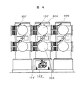
図3は、本発明の一実施の形態例に係るガス遮断器を備えたガス絶縁開閉装置の側面図であり、図4は、図3のガス絶縁開閉装置の正面図である。
【0022】
操作器を、機器の保守点検時、又はトラブルの発生時、操作器箱から取り外す場合を想定し、図3、図4を用いて説明する。機器据え付け面積の低減は社会的ニーズとして強く要求されているため、図3、図4に示すように、各機器は非常に接近して設置されることが多くなってきている。
【0023】
本ガス絶縁開閉装置は、本発明の一実施の形態例に係るガス遮断器100'と、発電所・変電所外より電力を引き込むための線路側接地容器302と、他回線機器306,307と電気的に接続する母線用接地容器303,304とで構成される。各接地容器内には、電力を輸送するための金属導体及び機械的に接離する接点を有している。
【0024】
図4に示すように、他回線機器306,307の各回線と当該回線が非常に近接しているため、操作器101'の保守点検作業を行う場合、機器のある一面(本図の場合はP矢印面)のみからのアクセスが可能なだけとなり、小型化された操作器箱111'の内部にまで十分なメンテナンス作業を施すことが困難であり、かつ性能維持上問題となっている。
【0025】
上記背景から、操作器101'を独立して操作器箱111'から完全に引き出した状態でメンテナンス作業を行うことは、点検作業の信頼性、作業性、安全性と言った観点からも大きな利点を有している。
【0026】
次に、操作器の着脱時の作業順序を、説明する。操作器101を操作器箱111内に搬入し、操作器101側の主出力軸102と接地容器側主回転軸110を連結する場合は、まず、図5に示すように、予め外筒スプラインギア106を接地容器側主回転軸110に取り付けられている主回転軸側スプラインギア105にネジ404を用いて固定し、また、操作器101側の主出力軸102に主出力軸側スプラインギア103を取り付けておく。
【0027】
次に、図6に示すように、滑車昇降ボルト500bをねじ込み、操作器101を浮かし、手動によって操作器101を操作器箱111内に格納して行く。移動用滑車500は操作器101に4箇所程度設けられており、左右前後任意に移動可能な球形状の車輪500aを有しており芯ずれの微調整を行うことが可能である。
【0028】
次に、操作器101の主出力軸102の中心と接地容器側主回転軸110の軸芯とが一致し外筒スプラインギア106が容易にかみ合うことを確認した後、操作器101を操作器箱取り付け板にボルト締めする。この時、ギアカップリング120は多少の軸同士の芯ずれを許容できるように、クラウニングと呼ばれるギアにR形状を施した加工となっている。
【0029】
本ギアカップリング120を適用する代わりに、一般的なスプラインを使用しても構造的には本発明と同様なガス遮断器を実現することは可能である。しかし、この場合、操作器脱着時に必然的に生じる操作器主出力軸と接地容器側主回転軸の芯ずれを吸収することは難しい。
【0030】
そのため、比較的作業の自由度の高い工場内組立作業時は取付け可能であっても、機器納入後の点検で操作器を一度取り外すと再度取り付けることは困難となる。これは一般的なスプラインの穴と軸が厳しい勘合となっているのと同時に軸穴の傾きを許容しない構造であるためである。
また、本発明では、ギアカップリング120のみの芯ずれ吸収可能寸法では、操作器101の取り外し後の取付けが不可能となる可能性を完全に排除するため、図7に示す工夫も施している。接地容器側主回転軸110を支持するボス130もギャップ131だけ移動可能なように配慮し、万が一ギアカップリング120のみで芯ずれを吸収できない時は、ギャップ131を調整し、芯ずれを吸収することができる。
【0031】
前述した構造により、組立性を向上させ、操作器点検時等に実施する操作器101の取外し、再組立作業を短時間に且つ容易に行うことが可能となった。
【0032】
また、機器の小形化による機器据え付け面積の低減と開閉時高速に動作する可動部品を操作器箱内に完全に収納することで点検時の安全性も向上させることが可能となった。
【0033】
【発明の効果】
本発明によれば、接地容器の略真下への操作器配置が可能となることで、ガス遮断器の小型化が図れ、ガス絶縁開閉装置の据付け面積の低減を図ることができる。
【0034】
また、接地容器側主回転軸と操作器の主出力軸とを、固定接触子と可動接触子との接離方向に同軸上に配置することにより、開閉時可動する部品数が低減でき、組立性を向上させることができる。
【0035】
また操作器の主出力軸と接地容器側主回転軸との連結に、ギアカップリングを用い、操作器に移動用滑車を取り付けることにより、操作器箱より完全に操作器を引き出すことができ、点検時作業性、メンテナンス作業性を大幅に向上させることができる。
【図面の簡単な説明】
【図1】本発明の一実施の形態例に係わるガス遮断器の構成を示す側面図である。
【図2】図1のガス遮断器のギアカップリングの詳細構造図である。
【図3】本発明の一実施の形態例に係るガス遮断器を備えたガス絶縁開閉装置の側面図である。
【図4】図3のガス絶縁開閉装置の正面図である。
【図5】操作器側の主出力軸と接地容器側主回転軸とを連結部を示す図である。
【図6】操作器に設けられた移動用滑車の詳細構造図である。
【図7】接地容器側主回転軸部の構成図である。
【図8】従来のガス絶縁開閉装置での操作器取付け構造を示す図である。
【符号の説明】
100,100'…ガス遮断器、101,101'…操作器、102…操作器主出力軸、103…主出力軸側スプラインギア、104…接地容器、105…主回転軸側スプラインギア、106…外筒スプラインギア、107…リンク、108,109…レバー、110…接地容器側主回転軸、111,111'…操作器箱、115…固定接触子、116…可動接触子、117…圧縮ばね、120…ギアカップリング、130…ボス、131…ギャップ、302…線路側接地容器、303,304…母線用接地容器、306,307…他回線機器、404…ネジ、500…移動用滑車、500a…車輪、500b…滑車昇降ボルト[0001]
BACKGROUND OF THE INVENTION
The present invention includes a gas circuit breaker including a current interrupting device including a stationary contact provided in a grounded container filled with an insulating gas and a movable contact contacting and separating from the stationary contact, and the same. The present invention relates to a gas insulated switchgear.
[0002]
[Prior art]
In a conventional gas circuit breaker, many parts are required to connect a movable part that moves the movable contact and an operation unit for transmitting driving force to the movable contact, and at the same time, rotation of the output shaft of the operation unit Once the system motion is converted to linear motion via a lever or rod, it is converted to rotational motion again, and then the movable contact is converted to linear motion again via a link or lever. doing.
[0003]
Further, in the insulated switchgear described in Japanese Patent Laid-Open No. 5-266765, as shown in FIG. 8 , the switchgear is provided with a space for arranging parts necessary for connection between the movable part in the
[0004]
[Problems to be solved by the invention]
As described above, when the connection structure and the operation device arrangement described in Japanese Patent Laid-Open No. 5-266765 are adopted, the operation device cannot be arranged directly under the switchgear body, in other words, the grounding container. There was a problem that the size became large, and social needs such as effective utilization of power plant / substation space and improvement of economic efficiency could not be sufficiently met.
[0005]
In addition, since the parts necessary for connecting the actuator and the movable parts to transmit the driving force to the movable contacts operate at high speed when opening and closing the current, there are problems from the viewpoint of work safety during maintenance and inspection. As the number of movable parts is large, the assembly becomes complicated and there are problems in assembling and quality. In addition, there is a problem that the mass of components to be driven increases during opening and closing, and it becomes difficult to reduce the operating device driving force for effectively driving the movable contact.
[0006]
An object of the present invention is to provide a gas circuit breaker and a gas-insulated switchgear that are small in size and easy to assemble and maintain.
[0007]
[Means for Solving the Problems]
In order to achieve the above object, the gas circuit breaker according to the present invention is characterized in that an operating device for driving a movable contact that contacts and separates from a fixed contact provided in the grounding container is located almost directly below the grounding container. And a grounding container side main rotating shaft connected to the movable contactor via the connecting member, and a rotational force for driving the movable contactor provided on the operating device via the grounding container side main rotating shaft. The main output shaft to output is coaxially arranged in the contact / separation direction of the fixed contact and the movable contact .
[0008]
Specifically, the present invention provides the following gas circuit breaker and gas insulated switchgear.
The present invention drives a ground sealed containers insulating gas, a current cut-off portion having a fixed contact and said fixed contact provided on the ground in the container toward and away from the movable contact, said movable contact in the gas circuit breaker and a operation unit you, together with the operating device is arranged substantially beneath the ground container, and the ground container side main axis of rotation coupled through a coupling member and the movable contact A main output shaft that outputs a rotational force for driving the movable contact via the grounded container side main rotation shaft provided in the operating device, and a contact / separation direction of the fixed contact and the movable contact The gas circuit breaker is characterized in that it is arranged coaxially .
[0009]
Preferably, the grounded container side main rotating shaft and the main output shaft are connected by a gear coupling.
[0010]
Preferably, the gear coupling includes a main output side spline gear attached to the main output shaft on the operation unit side, a main rotation shaft side spline gear attached to the grounded container side main rotation shaft, and the main output. A side spline gear and an outer cylinder spline gear that connects the main rotary shaft side spline gear.
[0011]
Preferably, the operating device includes a moving pulley that moves the operating device up, down, front, back, left, and right .
[0012]
Further, the present invention has each of the metallic conductors and mechanically toward and away from the contacts for transporting power, and bus ground container, comprising a gas circuit breaker, and a line-side grounding container, said gas circuit breaker , a ground sealed containers insulating gas, a current cut-off portion having a toward or away from the movable contact fixed contacts and the stationary contacts provided on the ground in a container, the driving force for driving the movable contact in the gas insulated switchgear having an operating device for outputting, together with the operating device is arranged substantially beneath the ground container, and the ground container side main axis of rotation coupled through a coupling member and the movable contact A main output shaft that outputs a rotational force for driving the movable contact via the grounded container side main rotation shaft provided in the operating device, and a contact / separation direction of the fixed contact and the movable contact It is coaxially disposed, and the main output In providing gas insulated switchgear characterized in that the rotational torque output is transmitted to the ground container side main rotational shaft through the gear coupling.
[0013]
DETAILED DESCRIPTION OF THE INVENTION
Hereinafter, a gas circuit breaker and a gas insulated switchgear including the same according to an embodiment of the present invention will be described with reference to the drawings.
[0014]
FIG. 1 is a side view showing a configuration of a gas circuit breaker according to an embodiment of the present invention.
[0015]
As shown in FIG. 1, the
[0016]
The
[0017]
In addition, the
[0018]
As described above, by disposing the
[0019]
In addition, safety can be improved by arranging movable parts that operate at a high speed in the
[0020]
FIG. 2 shows a detailed structure of the
[0021]
FIG. 3 is a side view of a gas insulated switchgear provided with a gas circuit breaker according to an embodiment of the present invention, and FIG. 4 is a front view of the gas insulated switchgear of FIG.
[0022]
The operation device will be described with reference to FIGS. 3 and 4 on the assumption that the operation device is removed from the operation device box at the time of maintenance and inspection of the device or when trouble occurs. Since reduction of equipment installation area is strongly demanded as a social need, as shown in FIGS. 3 and 4, each equipment is often installed very close.
[0023]
This gas insulated switchgear is electrically connected to a
[0024]
As shown in FIG. 4, each line of the
[0025]
From the above background, it is a great advantage from the viewpoint of reliability, workability, and safety of inspection work to perform maintenance work with the controller 101 'being completely pulled out from the controller box 111' independently. have.
[0026]
Next, the work sequence when attaching and detaching the operation device will be described. When the
[0027]
Next, as shown in FIG. 6, the
[0028]
Next, after confirming that the center of the
[0029]
Instead of applying the
[0030]
For this reason, even if it can be attached during assembly work in the factory with a relatively high degree of freedom of work, it is difficult to reattach it once the operating device is removed during inspection after delivery of the equipment. This is because a general spline hole and shaft have a strict fit, and at the same time the shaft hole is not allowed to tilt.
Further, in the present invention, in order to completely eliminate the possibility that it is impossible to attach the
[0031]
With the structure described above, it is possible to improve the assemblability, and to remove and reassemble the
[0032]
In addition, it has become possible to improve the safety at the time of inspection by reducing the equipment installation area by downsizing the equipment and completely storing the moving parts that operate at high speed when opening and closing in the actuator box.
[0033]
【The invention's effect】
According to the present invention, since the operation device can be arranged almost directly below the grounded container, the gas circuit breaker can be reduced in size, and the installation area of the gas insulated switchgear can be reduced.
[0034]
In addition, by arranging the grounded container side main rotating shaft and the main output shaft of the actuator coaxially in the contact / separation direction of the fixed contact and the movable contact, the number of parts that can be moved during opening and closing can be reduced, and assembly Can be improved.
[0035]
In addition, by using a gear coupling to connect the main output shaft of the controller to the grounded container side main rotating shaft, and attaching a moving pulley to the controller, the controller can be pulled out completely from the controller box. Workability at the time of inspection and maintenance workability can be greatly improved.
[Brief description of the drawings]
FIG. 1 is a side view showing a configuration of a gas circuit breaker according to an embodiment of the present invention.
2 is a detailed structural diagram of a gear coupling of the gas circuit breaker of FIG. 1;
FIG. 3 is a side view of a gas insulated switchgear including a gas circuit breaker according to an embodiment of the present invention.
4 is a front view of the gas insulated switchgear of FIG. 3;
FIG. 5 is a view showing a connecting portion between the main output shaft on the operating device side and the main rotating shaft on the ground container side.
FIG. 6 is a detailed structural diagram of a moving pulley provided in an operating device.
FIG. 7 is a configuration diagram of a grounded container side main rotating shaft portion;
FIG. 8 is a view showing a structure for mounting an operating device in a conventional gas insulated switchgear.
[Explanation of symbols]
100,100 '... Gas circuit breaker, 101,101' ... Operator, 102 ... Operator main output shaft, 103 ... Main output shaft side spline gear, 104 ... Grounding vessel, 105 ... Main rotary shaft side spline gear, 106 ... Outer cylinder spline gear , 107: Link, 108, 109 ... Lever, 110: Grounded container side main rotating shaft, 111, 111 '... Actuator box, 115 ... Fixed contact, 116 ... Movable contact, 117 ... Compression spring, 120 ... Gear coupling, 130 ... Boss, 131 ... Gap, 302 ... Line side grounding container, 303,304 ... Bus grounding container, 306,307 ... Other line equipment, 404 ... Screw, 500 ... Movement pulley, 500a ... Wheel, 500b ... Pulse lift bolt
Claims (5)
前記操作器が前記接地容器の略真下に配置されていると共に、前記可動接触子と連結部材を介して連結する接地容器側主回転軸と、前記操作器に設けられ前記接地容器側主回転軸を介して前記可動接触子を駆動するための回転力を出力する主出力軸とが、前記固定接触子と可動接触子との接離方向に同軸上に配置されていることを特徴とするガス遮断器。A ground sealed containers insulating gas, a current cut-off portion having a toward or away from the movable contact fixed contacts and the stationary contacts provided on the ground in the container, operation you drive the movable contact A gas circuit breaker comprising
The operating device is disposed substantially directly below the grounded container, and is connected to the movable contactor via a connecting member. The grounded container side main rotating shaft is provided in the operating device, and the grounded container side main rotating shaft is provided. And a main output shaft that outputs a rotational force for driving the movable contact via the gas is arranged coaxially in the contact / separation direction of the fixed contact and the movable contact. Circuit breaker.
、前記操作器が前記接地容器の略真下に配置されていると共に、前記可動接触子と連結部材を介して連結する接地容器側主回転軸と、前記操作器に設けられ前記接地容器側主回転軸を介して前記可動接触子を駆動するための回転力を出力する主出力軸とが、前記固定接触子と可動接触子との接離方向に同軸上に配置され、かつ前記主出力軸で出力する回転トルクがギアカップリングを介して前記接地容器側主回転軸に伝達されることを特徴とするガス絶縁開閉装置。Encapsulating each having a metallic conductor and mechanically toward and away from the contacts for transporting power, and bus ground container, and a gas circuit breaker, and a line-side grounding container, said gas circuit breaker, an insulating gas a ground containers, a current cut-off portion having a fixed contact and said fixed contact provided in the ground within the container toward and away from the movable contact, and an operating unit for outputting a driving force for driving the movable contact In a gas insulated switchgear having
The operating device is disposed substantially directly below the grounded container, and is connected to the movable contactor via a connecting member, and the grounded container side main rotating shaft is provided in the operating device, and the grounded container side main rotation is provided. A main output shaft that outputs a rotational force for driving the movable contact through a shaft, and is disposed coaxially in the contact / separation direction of the fixed contact and the movable contact , and the main output shaft gas insulated switchgear, characterized in that the rotational torque output is transmitted to the ground container side main rotational shaft through the gear coupling.
Priority Applications (5)
| Application Number | Priority Date | Filing Date | Title |
|---|---|---|---|
| JP29259399A JP3663090B2 (en) | 1999-10-14 | 1999-10-14 | Gas circuit breaker and gas insulated switchgear provided with the same |
| EP00119186A EP1093140A3 (en) | 1999-10-14 | 2000-09-05 | Gas-insulated circuit breaker and gas-insulated switch-gear having the same |
| TW089118161A TW522419B (en) | 1999-10-14 | 2000-09-05 | Gas-insulated circuit breaker and gas-insulated switch-gear having the same |
| US09/679,044 US6407908B1 (en) | 1999-10-14 | 2000-10-04 | Gas-insulated circuit breaker and gas-insulated switch-gear having the same |
| KR10-2000-0059661A KR100454864B1 (en) | 1999-10-14 | 2000-10-11 | Gas-insulated circuit breaker and gas-insulated switch-gear having the same |
Applications Claiming Priority (1)
| Application Number | Priority Date | Filing Date | Title |
|---|---|---|---|
| JP29259399A JP3663090B2 (en) | 1999-10-14 | 1999-10-14 | Gas circuit breaker and gas insulated switchgear provided with the same |
Publications (2)
| Publication Number | Publication Date |
|---|---|
| JP2001118474A JP2001118474A (en) | 2001-04-27 |
| JP3663090B2 true JP3663090B2 (en) | 2005-06-22 |
Family
ID=17783799
Family Applications (1)
| Application Number | Title | Priority Date | Filing Date |
|---|---|---|---|
| JP29259399A Expired - Fee Related JP3663090B2 (en) | 1999-10-14 | 1999-10-14 | Gas circuit breaker and gas insulated switchgear provided with the same |
Country Status (5)
| Country | Link |
|---|---|
| US (1) | US6407908B1 (en) |
| EP (1) | EP1093140A3 (en) |
| JP (1) | JP3663090B2 (en) |
| KR (1) | KR100454864B1 (en) |
| TW (1) | TW522419B (en) |
Families Citing this family (18)
| Publication number | Priority date | Publication date | Assignee | Title |
|---|---|---|---|---|
| KR100474380B1 (en) * | 2002-03-07 | 2005-03-09 | 엘지산전 주식회사 | Power transmisson device of c.b. mechanism in g.i.s. |
| ES2424480T3 (en) | 2002-05-14 | 2013-10-02 | Schreiner Group Gmbh & Co. Kg | Authentication patterns visible for printed document |
| TWI228339B (en) * | 2002-11-06 | 2005-02-21 | Mitsubishi Electric Corp | Metal-enclosed switchgear |
| CN101300720B (en) * | 2006-03-31 | 2011-08-24 | 三菱电机株式会社 | Air insulation electric power apparatus |
| JP5116589B2 (en) | 2008-07-15 | 2013-01-09 | 三菱電機株式会社 | Power switchgear |
| US8355243B2 (en) * | 2011-01-27 | 2013-01-15 | Eaton Corporation | Closed door circuit breaker racking extension |
| CN102832073B (en) * | 2012-08-16 | 2015-08-19 | 河南平高电气股份有限公司 | A kind of direct current valve hall earthed switch and ground connection conducting rod mechanism thereof |
| JP5883941B2 (en) * | 2012-09-18 | 2016-03-15 | 株式会社日立製作所 | Gas insulated switchgear |
| JP2014107179A (en) * | 2012-11-29 | 2014-06-09 | Hitachi Ltd | Three-phase bulk operation circuit breaker |
| JP6236240B2 (en) * | 2013-07-23 | 2017-11-22 | 株式会社東芝 | Gas circuit breaker |
| JP6069173B2 (en) * | 2013-11-15 | 2017-02-01 | 株式会社日立製作所 | Gas circuit breaker |
| JP5627821B1 (en) * | 2014-01-20 | 2014-11-19 | 三菱電機株式会社 | Gas insulated switchgear |
| DE102016213158A1 (en) * | 2016-07-19 | 2018-01-25 | Siemens Aktiengesellschaft | Switchgear arrangement |
| JP6346355B2 (en) * | 2017-07-07 | 2018-06-20 | 株式会社東芝 | Gas circuit breaker |
| DE102017214543A1 (en) * | 2017-08-21 | 2019-02-21 | Siemens Aktiengesellschaft | coupling member |
| CN107919624B (en) * | 2017-11-10 | 2024-05-14 | 国网浙江省电力公司台州供电公司 | Platform for overhauling chassis truck of 10kV circuit breaker |
| CN108572067A (en) * | 2018-06-08 | 2018-09-25 | 河南华盛隆源电气有限公司 | Breaker operation mechanism test fixture |
| CN115836372A (en) * | 2020-08-24 | 2023-03-21 | 株式会社东芝 | Opening and closing device |
Family Cites Families (12)
| Publication number | Priority date | Publication date | Assignee | Title |
|---|---|---|---|---|
| US3794799A (en) * | 1972-03-27 | 1974-02-26 | Westinghouse Electric Corp | Gas insulated switch with adjustable overcenter toggle actuator therefore |
| US4101748A (en) * | 1976-05-12 | 1978-07-18 | Westinghouse Electric Corp. | Modular puffer-type circuit-interrupter unit adaptable for different voltage and current ratings |
| DE2911759C2 (en) * | 1979-03-26 | 1984-11-29 | Brown, Boveri & Cie Ag, 6800 Mannheim | Detachable coupling for connecting the drive piston rod for an electrical high-voltage circuit breaker |
| CH649866A5 (en) * | 1980-07-02 | 1985-06-14 | Sprecher & Schuh Ag | High-voltage power circuit breaker having a drive rod consisting of insulating material |
| JPS5869414A (en) * | 1981-10-16 | 1983-04-25 | 株式会社日立製作所 | Gas insulated switching device |
| DE3417299A1 (en) * | 1984-02-14 | 1985-10-10 | BBC Aktiengesellschaft Brown, Boveri & Cie., Baden, Aargau | Metal-encapsulated, gas-insulated switching installation |
| JPH05266765A (en) * | 1992-03-23 | 1993-10-15 | Mitsubishi Electric Corp | Switchgear |
| FR2719153B1 (en) * | 1994-04-21 | 1996-05-24 | Gec Alsthom T & D Sa | Connection between a circuit breaker pole and its control. |
| DE4419380C1 (en) * | 1994-05-30 | 1995-10-19 | Siemens Ag | Circuit breaker module |
| JPH0982183A (en) * | 1995-09-14 | 1997-03-28 | Nissin Electric Co Ltd | Gas-insulated switch gear |
| JPH1153998A (en) * | 1997-08-07 | 1999-02-26 | Mitsubishi Electric Corp | Gas circuit breaker |
| JP2000182483A (en) * | 1998-12-14 | 2000-06-30 | Nissin Electric Co Ltd | Operating shaft connecting device of gas-insulated switch apparatus |
-
1999
- 1999-10-14 JP JP29259399A patent/JP3663090B2/en not_active Expired - Fee Related
-
2000
- 2000-09-05 EP EP00119186A patent/EP1093140A3/en not_active Withdrawn
- 2000-09-05 TW TW089118161A patent/TW522419B/en not_active IP Right Cessation
- 2000-10-04 US US09/679,044 patent/US6407908B1/en not_active Expired - Lifetime
- 2000-10-11 KR KR10-2000-0059661A patent/KR100454864B1/en active IP Right Grant
Also Published As
| Publication number | Publication date |
|---|---|
| KR100454864B1 (en) | 2004-11-03 |
| TW522419B (en) | 2003-03-01 |
| EP1093140A2 (en) | 2001-04-18 |
| JP2001118474A (en) | 2001-04-27 |
| US6407908B1 (en) | 2002-06-18 |
| KR20010040048A (en) | 2001-05-15 |
| EP1093140A3 (en) | 2002-10-30 |
Similar Documents
| Publication | Publication Date | Title |
|---|---|---|
| JP3663090B2 (en) | Gas circuit breaker and gas insulated switchgear provided with the same | |
| EP2546850B1 (en) | Switchgear and method for operating switchgear | |
| KR101716284B1 (en) | Gas-insulated switchgear | |
| WO2012086293A1 (en) | Power switch device | |
| US9953778B2 (en) | Gas circuit breaker and breaker for gas insulated switching device | |
| US3562465A (en) | Telescopic switch for isolated phase bus | |
| KR101697633B1 (en) | Gas circuit breaker | |
| JP6625268B1 (en) | Gas insulated switchgear | |
| JP4062043B2 (en) | Gas insulated switchgear | |
| JP5661223B1 (en) | Gas insulated switchgear and switchgear | |
| CN217690932U (en) | Operating mechanism for grounding switch and grounding switch | |
| US3339037A (en) | High voltage switch construction | |
| CN217822534U (en) | Operating mechanism for isolating grounding switch and isolating grounding switch | |
| CN201781453U (en) | Mining explosion-proof high-voltage vacuum alternating-current soft starter with isolation locking device | |
| KR100486372B1 (en) | Gas Insulated Switchgear | |
| JP2001229792A (en) | Switchgear | |
| KR102485880B1 (en) | DS/ES Operating Mechanism of Gas Insulated Switchgear | |
| KR102406039B1 (en) | Interlock device for ground switch of rail vehicles | |
| JPH06275177A (en) | Vacuum circuit breaker and high-tension receiving and distributing device | |
| EP1124241A1 (en) | Vacuum switch gear | |
| CN220543798U (en) | Operating mechanism and combined circuit breaker | |
| JP2014165033A (en) | Operating section for switch | |
| KR100823829B1 (en) | Operator for gas insulated switchcgear | |
| JP4202468B2 (en) | Switchgear | |
| KR100788165B1 (en) | Manual operator for gas insulator switchgear |
Legal Events
| Date | Code | Title | Description |
|---|---|---|---|
| A977 | Report on retrieval |
Free format text: JAPANESE INTERMEDIATE CODE: A971007 Effective date: 20040610 |
|
| A131 | Notification of reasons for refusal |
Free format text: JAPANESE INTERMEDIATE CODE: A131 Effective date: 20040615 |
|
| A521 | Written amendment |
Free format text: JAPANESE INTERMEDIATE CODE: A523 Effective date: 20040810 |
|
| TRDD | Decision of grant or rejection written | ||
| A01 | Written decision to grant a patent or to grant a registration (utility model) |
Free format text: JAPANESE INTERMEDIATE CODE: A01 Effective date: 20050308 |
|
| A61 | First payment of annual fees (during grant procedure) |
Free format text: JAPANESE INTERMEDIATE CODE: A61 Effective date: 20050325 |
|
| R150 | Certificate of patent or registration of utility model |
Ref document number: 3663090 Country of ref document: JP Free format text: JAPANESE INTERMEDIATE CODE: R150 Free format text: JAPANESE INTERMEDIATE CODE: R150 |
|
| FPAY | Renewal fee payment (event date is renewal date of database) |
Free format text: PAYMENT UNTIL: 20090401 Year of fee payment: 4 |
|
| FPAY | Renewal fee payment (event date is renewal date of database) |
Free format text: PAYMENT UNTIL: 20100401 Year of fee payment: 5 |
|
| FPAY | Renewal fee payment (event date is renewal date of database) |
Free format text: PAYMENT UNTIL: 20110401 Year of fee payment: 6 |
|
| FPAY | Renewal fee payment (event date is renewal date of database) |
Free format text: PAYMENT UNTIL: 20120401 Year of fee payment: 7 |
|
| FPAY | Renewal fee payment (event date is renewal date of database) |
Free format text: PAYMENT UNTIL: 20120401 Year of fee payment: 7 |
|
| FPAY | Renewal fee payment (event date is renewal date of database) |
Free format text: PAYMENT UNTIL: 20130401 Year of fee payment: 8 |
|
| FPAY | Renewal fee payment (event date is renewal date of database) |
Free format text: PAYMENT UNTIL: 20140401 Year of fee payment: 9 |
|
| LAPS | Cancellation because of no payment of annual fees |