JP3662007B2 - Fixed piston sampler with cone function - Google Patents
Fixed piston sampler with cone function Download PDFInfo
- Publication number
- JP3662007B2 JP3662007B2 JP2002200500A JP2002200500A JP3662007B2 JP 3662007 B2 JP3662007 B2 JP 3662007B2 JP 2002200500 A JP2002200500 A JP 2002200500A JP 2002200500 A JP2002200500 A JP 2002200500A JP 3662007 B2 JP3662007 B2 JP 3662007B2
- Authority
- JP
- Japan
- Prior art keywords
- ground
- piston
- cone
- hollow
- sampler
- Prior art date
- Legal status (The legal status is an assumption and is not a legal conclusion. Google has not performed a legal analysis and makes no representation as to the accuracy of the status listed.)
- Expired - Lifetime
Links
Images
Landscapes
- Investigation Of Foundation Soil And Reinforcement Of Foundation Soil By Compacting Or Drainage (AREA)
- Sampling And Sample Adjustment (AREA)
Description
【0001】
【発明の属する技術分野】
本発明は、地盤調査を行う複数の測定センサを備えたサンプラーを、土中深く進入し、地盤内における地盤検査を行うことができる地盤検査方法にかかり、先端のコーン部分に地盤調査用の複数の検査用センサを配置したコーン機能付固定ピストンサンプラーに関する。
【0002】
【従来の技術】
従来の地盤検査装置は、ボーリング孔を利用し、試料採取用円筒(シリンダ)のサンプラーを押し込み、孔底の試料を採取し、地上の土質試験室において1軸圧縮試験などの各種土質試験を行って地盤の成分や強さを検査して特性値を測定している。このようなサンプラーとしては水圧サンプラー、回転掘削式の二重管式サンプラー、および三重サンプラーなどがある。この場合、サンプラーの直径が大きいため大径のボーリングを行う必要があり、試験費用が嵩む問題があった。また、土質調査方法としてサウンディングという方法がある。この方法は地盤にプローブ(試験錘)を押し込んで地盤の耐力を直接計測するものである。サウンディングの一方法としてコーン貫入試験があり、その多くは地耐力だけではなく、地盤の間隙水圧やプローブ側面の摩擦力を測定することが行われ、一般に三成分コーン貫入試験と呼ばれている。
【0003】
サウンディングの別な方法としては標準貫入試験がある。標準貫入試験(JISA1219)はボーリング孔の孔底に一定形状のブローブを一定の質量を持つハンマーを一定の高さから落下打撃させ、一定の長さだけ地盤に貫入する打撃回数をN値として記録するもので、わが国では最も一般的な地盤検査方法である。しかし標準貫入試験は地盤では地耐力の判定に精度の問題が生じ、サンプリングによる地盤定数の確認か、あるいは三成分コーンなどによる貫入試験が推奨されている。標準貫入試験中に比較的軟弱な地盤に遭遇した場合にはサンプリングを諦めるか、サンプリングのために新しい大径のボーリング作業を行う必要があった。
【0004】
前述のような地盤検査用のサンプラー装置としては円筒(シリンダ)内を作動媒体によりピストンが摺動し、ピストンの先端に取り付けられたサンプラーチューブが地盤に貫入し、地盤の資料をサンプラーチューブ内に収納して地上に取り出す水圧サンプラーが一般的である。通常の水圧サンプラーはコア径が75mmでサンプラーを孔底に挿入するため86mmのボーリング孔径が採用される。一方標準貫入試験ではプローブ径が51mmであるためボーリング孔径は66mmが採用されている。従って、標準貫入試験中に比較的軟弱な地盤に遭遇し、サンプリングの必要を生じた場合には新たに口径の大きなボーリングを行う必要があった。
【0005】
前述のサウンディングのように試料を採取せずに地盤の特性を判定する方法として地表から連続して前記三成分コーン貫入試験によって地質などを検査し、その孔底の測定データなどの信号を地上に伝送するために有線方式が一般的である。この場合は、複数の中空管を繋ぎながら地中深くコーンを押し込むので予め必要な長さの信号線を通しておくもので、九十九折に収納されていた。このような有線方式に代え、地上への伝送手段として電磁波を利用する送信装置などがある。例えば、特開昭63−77229号公報及びに米国特許第4,496,174号明細書に記載されている。これらは上下に分割して配置したドリルカラー間に絶縁物を介在し、この絶縁物の間にセンサを配置するもの、上下のドリルカラーに接続した導体間に電磁波を生じるものである。
【0006】
【発明が解決しようとする課題】
従来は、ボーリングにより地盤に孔を掘削し、このボーリング孔を利用して、サンプラなどを挿入して試料を採取していた。
地中においてサンプラにより採取した試料を運搬して検査室において検査する方法とサウンディングにより原位置で地盤情報を得る方法はおのおの得失があり、いずれも多用されているが場合によってはその一方を採用することが推奨されている。サウンディングをしながら孔底に下ろした器具を取り替えることなしにサンプリングをすることはできなかった。サウンディングのうちコーン貫入試験においては孔底の地盤情報を取り出すために有線式を採用することは電線の取扱いに困難であった。他方、地底からの送信装置を利用して地上の受信装置に伝播する場合は、電磁波の到達距離に限界があり、マッドパルス方式などの衝撃による方法は情報量に限界があった。
【0007】
本発明の課題は、地盤にボーリングによる穿孔を行うことなく、中空管内に内蔵する固定ピストンによって先端部に配置したコーン先端を地中に挿入して地盤の状況を検査する簡易な方法を提供することである。
本発明の課題は、標準貫入試験中に遭遇し、補完的にコーン貫入試験やサンプリングを行う場合に器具の入れ替えを行うことなく、標準貫入試験の孔内で精度の高いコーン貫入試験と地盤サンプリングを選択できる装置を提供することにある。
本発明の他の課題は、リアルタイムで地盤の地耐力、間隙水圧、コーン側壁面の摩擦力などの多くの情報の信号量を把握できるコーン機能付固定ピストンサンプラーを提供することである。
本発明のその他の課題は、従来の小径倍圧式水圧ピストンサンプラーを利用して比較的硬質な地盤などにも推進可能で、標準貫入試験中にも計測でき、正確な地盤の測定データを伝送できるコーン機能付固定ピストンサンプラーを提供することである。
本発明の他の課題は、その都度実験室に地中の試料を持ち帰ることなく、サンプラーを地中深く挿入して計測した地盤データを正確に地上に伝送できるコーン機能付固定ピストンサンプラーを提供することである。
【0008】
【課題を解決するための手段】
本発明の前記課題は以下の構成によって達成できる。
地盤内に中空管を挿入して地盤を調査する固定ピストンサンプラーにおいて、中空管をピストンのシリンダとし、このシリンダ本体及びピストンロッドを固定する接続具を配置し、このシリンダ本体およびピストンロッドで形成される環状部分内で摺動自在に支持される中空ピストンを内蔵し、この中空ピストンの先端側にチューブを固持し、前記中空ピストン内に形成される中空室を上下室に分割する仕切部材を前記ピストンロッドに固定し、前記接続具と前記中空ピストンの上室との間の空間及び分割された前記中空ピストンの中空室の下室内に作動媒体を供給する供給路を設け、前記中空ピストンの先端部分に配設したコーン部が交換可能に取付けられ、このコーン部に地盤検査用の各種センサを配置してなるコーン機能付固定ピストンサンプラーの構成である。
【0010】
本発明の前記課題は、前記コーン部に設ける地盤検査用センサとして地耐力、地盤の間隙水圧、コーン部の側壁摩擦力などのセンサの他に温度、エス波、ラヂオアイソトープ(RI)、密度、アコ−ステイックエミッション(AE)、比抵抗、塩分濃度、自然電位、伝導度、P波、傾斜度、ジャイロ及びPH値等を計測するセンサを配置してあるコーン機能付固定ピストンサンプラーによって達成できる。
【0011】
また、前記課題は、前記コーン部に設けた前記各センサによる計測データを演算処理、増幅処理して送信する送信装置を前記中空管や前記チューブ内に配備してなる構成、又は前記コーン部の先端部分に配置した地盤検査項目の前記各センサ各計測データが演算処理部により解析処理され、処理されたデータを超音波発生装置、演算回路及び振幅差検出回路によってデータ変換し、超音波振動子によって発生される超音波により伝播し、この超音波信号を地上の受信装置によって受信し、表示装置や出力装置に出力して地盤状況を把握する構成のコーン機能付固定ピストンサンプラーによって達成できる。
【0012】
本発明のコーン機能付固定ピストンサンプラーは、水圧ピストンであっても強度の大きい粘性土地盤に対して大きな推進力を有し、比較的小径のボーリング孔を利用して十分な検査ができる。また、地中深く挿入して、従来の三成分コーンによる測定データや地盤の状況を地上にリアルタイムで送信することができる。特に、超音波振動子による小型の発信器および電池電源を利用して測定データを地上にて受信して観察することができる。
【0013】
本発明のコーン機能付固定ピストンサンプラーは、地盤にコーン先端をあてがい、中空ピストンによって地盤内にコーン部を深く挿入し、またはボーリングによって穿孔された竪孔内にコーン部を挿入し、先端のコーン部を地盤内に挿入して、先端部のコーンに配置した各種地盤計測用のセンサにより検出した計測データをコンピュータにより演算処理して解析し、その測定結果の地盤データを超音波振動子によって送信することができるからリアルタイムに測定データを取得することができる。
本発明のコーン機能付固定ピストンサンプラーにおいても、サンプラーによる試料採集が行われることは当然である。
【0014】
【発明の実施の形態】
以下、本発明のコーン機能付固定ピストンサンプラーについて実施の形態に基づき図面を参照して詳述する。
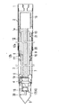
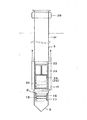
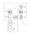
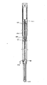
図1は本発明コーン機能付固定ピストンサンプラーにおける1実施形態の中空管の内部機構を示す説明図である。図2は図1の実施形態の概略説明図である。図3は本発明のコーン機能付固定ピストンサンプラーのブロック図である。図4は本発明のコーン機能付固定ピストンサンプラーを備えた1実施形態の一部省略した全体図である。
【0015】
本発明のコーン機能付固定ピストンサンプラーについて図面に示す実施形態に基づいて説明する。
接続具1を介在して中空薄肉円筒管であるシリンダ2を複数連結してある。このシリンダ2内にはピストンロッド7が配置してあり、このピストンロッド7は接続具1にねじ込み接続する。この接続具1にはピストンを動作する作動水の供給路1aが形成してある。
ピストンロッド7の中間部に第2ピストン9がロックナット10によりピストンロッド7に固定され、ピストンロッド7の先端には固定ピストン6と測定部4及びコーン部5がねじ溝で連結され、コーン部5に測定部4に軸方向自在に連結されている。
前記シリンダ2内にはシリンダ2の内面とピストンロッド7の外周に接触し、軸方向に摺動可能な第1ピストン13があり、第1ピストン13にはシリンダチューブ8とその先にヘッド11がねじ溝で接続されている。ヘッド11にはチューブ3が止めねじ溝により接続されている。シリンダチューブ8の内面には前記第2ピストン9が水密に接している。
【0016】
シリンダチューブ8内の中空室12は第2ピストン9により上室12aと下室12bとに仕切られ、第2ピストン9はこの中空室12内を摺動する。これらの各ピストン部材の周壁面にはOリング19、20、21が埋設してあり、シーリングされている。11はチューブ3に固定したヘッドで、第1ピストン13の上部及び中空室12b内の水圧によってシリンダチューブ8と共に移動する。このシリンダチューブ8に固着した第1ピストン13がシリンダ2内に摺動するように配置してあり、接続具1の作動水の供給路1aからの水圧によって第1ピストン13はシリンダ2内を移動する。15はシリンダ2内に配設した送信電装部である。
【0017】
ピストンロッド7の先端には交換可能に取り付けられたコーン部5及び測定部4が配備され、このコーン部5及び測定室4には地盤検査用の各種センサが配置してある。例えば、水圧センサ17、地耐力センサ16、コーン側壁の摩擦力センサ18などで、その他、温度、エス波、ラジオアイソトープ(ガンマー線、中性子)、密度、アコーステイックエミッション、比抵抗、水素イオン濃度(PH値)、塩分濃度、自然電位、伝導度、P波、傾斜度、ジャイロなどを計測するセンサを配置することができる。
【0018】
シリンダ2内には電源装置と共に地上へ計測データを送信する送信電装部15(電源部を含む)への信号を処理する処理装置が内蔵してある。図面に示す一例は、情報量が比較的多い超音波装置である。
この超音波装置は、超音波振動子22、電源部の電池23、超音波発生部24(デジタル)、超音波発生部(アナログ)25及び制御演算回路26を内蔵し、この測定部4は荷重受け座、レジューサを介してコーン部5が接続してある。
【0019】
このコーン部5は小さく設計されているので内装する機器類は限定される。従って、各計測センサの地耐力、間隙水圧、及びコーン側壁摩擦力の各計測センサなどのデータ信号を送信する送信機はシリンダ2内に配置してあり、測定部4と送信電装部15との間はピストンロッド7内に配線して送信電装部15にデータ信号が伝送され、この送信電装部15の超音波信号がシリンダ2および接続具1の上部に連結したボーリングロッド31を伝播して地上の受信ユニット29に送信する。この受信ユニット29は信号増幅部、周波数検出部、データ復調部及びデータ表示、出力部からなっている。30はフィルタである。
【0020】
本発明のコーン機能付固定ピストンサンプラーは、図4に示されるようにシリンダ2、2を接続具1の上部に接続したボーリングロッド31により地上のボーリングマシンからの推進力を伝達され、ピストンロッド7の先端に取り付けられたコーン部5を地中深く押し込むことができる。コーン部5に取り付けられた水圧センサ17、コーン側壁の摩擦力センサ18及び地耐力センサ16によって原位置で正確な地盤定数を知ることができる。
【0021】
本発明のコーン機能付固定ピストンサンプラーにおける測定部4について詳細に説明する。
この測定部4はコーン部5の水圧センサ17、地耐力センサ16及びコーン側壁の摩擦力センサ18によって地盤貫入抵抗力、水圧、及び側壁の摩擦力の信号が電圧変換されて、送信電装部15のインターフェイス14に入力される。このアナログ信号を増幅してデジタル信号に変換し、このデジタル信号は演算処理回路に取り込まれ、地質の解析が行われ、この地質データを送信信号発生部に設定することによりデジタルのバースト信号に変換する。
【0022】
このデジタルのバースト信号は送信信号発生部にてアナログ信号で超音波を発生すべく高電圧のサイン波に変換され、超音波振動子の両端にかけられ、超音波に変換される。この超音波振動子はシリンダ2の内面に隙間なく張り付けられ、この超音波振動子の振動はシリンダ2、接続具1及びボーリングロッド31を伝送媒体として地上に伝達する。
【0023】
前記チューブ3の長さはコーン部5の先の地盤に300〜400mm貫入できる十分な長さを必要とする。コーン部5は断面積が10cmとなるように35.7mmの直径を取ることが普通であるためチューブ3の直径は40mm以上の適当な値を採用するとよい。
【0024】
本発明の図1に示す実施形態のコーン機能付固定ピストンサンプラーは、先端のコーン部を地盤に挿入するに際して、実施例としてボーリングによって穿孔した縦穴の底部にコーン部5を貫入させる方法について説明する。
地盤の地中深くコーン部5を挿入してコーン部5内部に設置された地耐力センサ16、水圧センサ17等の信号を超音波発生器24、25を利用した信号伝達によって地盤の力学的な定数をリアルタイムに知り、地盤データ試料を採取する場合にはその状態のままでコーン部5の貫入を停止し、ボーリングロッド31を通じて水圧を供給することによって水圧がシリンダ2内部の第1ピストン13の上面および中空室12の下室12bに作動してチューブ13が地盤に貫入して地盤試料を採取する。
【0025】
リアルタイムの検査測定データのみならず地盤を調査するための試験サンプルを採取するには、第1ピストン13、シリンダチューブ8、ヘッド11及びチューブ3は作動水の供給路1aおよびピストンロッド7内の通路を通過してシリンダチューブ8の下室12bに供給され、この作動水の圧力により第1ピストン13の上面及びヘッド11の上面に力を受け、接続具1及び先端のコーン部5に対してシリンダ2内を下方に摺動し、チューブ3は地盤内に貫入して地盤試料をチューブ3内に収納して地盤のサンプリングを行うことができる。
【0026】
【発明の効果】
本発明のコーン機能付固定ピストンサンプラーによれば、コーン部を地中深く挿入し、コーン先端に配置した各種センサの信号を超音波発生器により伝播させて地盤の力学的な定数をリアルタイムに知ることができる。しかも地盤試料を採取する場合にはその状態のままでコーン部の外周面のチューブを地盤に貫入させて行うことができるから、新たに器具の交換など行う必要がない。特に、倍力機構によって比較的小径のボーリング孔を利用してコーン部を貫入させ、強度の大きい粘性土地盤や砂礫層などの掘削し難い地盤においても地盤調査をすることができる。特に、標準貫入試験中であっても地盤調査を行うことができる。
【図面の簡単な説明】
【図1】本発明のコーン機能付固定ピストンサンプラーの1実施形態の内部機構を示す説明図である。
【図2】図1の実施形態の概略説明図である。
【図3】本発明のコーン機能付固定ピストンサンプラーの伝送装置として超音波装置を使用した1実施形態のブロック図である。
【図4】本発明のコーン機能付固定ピストンサンプラーの1実施形態の一部省略した全体図である。
【符号の説明】
1 接続具
2 シリンダ
3 チューブ
4 測定部
5 コーン部
6 固定ピストン
7 ピストンロッド
8 シリンダチューブ
9 第2ピストン
10 ロックナット
11 ヘッド
12 中空室
13 第1ピストン
14 インターフェイス
15 送信電装部
16 地耐力センサ
17 水圧センサ
18 摩擦力センサ
19,20,21 Oリング
22 超音波振動子
24 超音波発生器(デジタル)
25 超音波発生器(アナログ)
26 演算回路(CPU)
29 受信ユニット
30 フィルタ[0001]
BACKGROUND OF THE INVENTION
The present invention relates to a ground inspection method in which a sampler provided with a plurality of measurement sensors for ground investigation can be advanced deeply into the soil and ground inspection can be performed in the ground. The present invention relates to a fixed piston sampler with a cone function in which sensors for inspection are arranged.
[0002]
[Prior art]
The conventional ground inspection equipment uses a borehole, pushes the sampler of the sampling cylinder (cylinder), collects the sample at the bottom of the hole, and performs various soil tests such as uniaxial compression tests in the soil test chamber on the ground. The characteristics and values are measured by examining the composition and strength of the ground. Examples of such a sampler include a hydraulic sampler, a rotary excavation type double pipe sampler, and a triple sampler. In this case, since the diameter of the sampler is large, it is necessary to perform large-diameter boring, and there is a problem that test costs increase. There is also a method called sounding as a soil survey method. This method directly measures the strength of the ground by pushing a probe (test weight) into the ground. One method of sounding is the cone penetration test, most of which measures not only the earth bearing strength but also the pore water pressure of the ground and the frictional force on the side of the probe, and is generally called the three-component cone penetration test.
[0003]
Another method of sounding is the standard penetration test. In the standard penetration test (JISA1219), a constant-shaped probe is dropped at the bottom of the boring hole and a hammer with a constant mass is dropped from a certain height, and the number of strikes that penetrate into the ground for a certain length is recorded as an N value. This is the most common ground inspection method in Japan. However, in the standard penetration test, there is a problem of accuracy in determining the ground strength on the ground, and it is recommended to check the ground constant by sampling or the penetration test using a three-component cone. When a relatively soft ground was encountered during the standard penetration test, it was necessary to give up sampling or perform a new large-diameter boring operation for sampling.
[0004]
In the sampler device for ground inspection as described above, the piston slides in the cylinder (cylinder) by the working medium, the sampler tube attached to the tip of the piston penetrates the ground, and the ground data is put in the sampler tube. A hydraulic sampler is generally stored and taken out to the ground. A normal hydraulic sampler has a core diameter of 75 mm and a bored hole diameter of 86 mm is used to insert the sampler into the hole bottom. On the other hand, in the standard penetration test, since the probe diameter is 51 mm, the borehole diameter is 66 mm. Therefore, when a relatively soft ground was encountered during the standard penetration test and a need for sampling occurred, it was necessary to newly drill a large bore.
[0005]
As in the sounding method described above, as a method of determining the characteristics of the ground without taking a sample, the geology and the like are inspected continuously by the three-component cone penetration test from the ground surface, and signals such as measurement data of the hole bottom are transmitted to the ground. A wired system is generally used for transmission. In this case, since the cone is pushed deeply into the ground while connecting a plurality of hollow tubes, the signal line having a necessary length is passed in advance, and it is stored in ninety-nine folds. In place of such a wired system, there is a transmission device using electromagnetic waves as a transmission means to the ground. For example, it is described in JP-A-63-77229 and US Pat. No. 4,496,174. In these, an insulator is interposed between drill collars that are divided vertically and a sensor is disposed between the insulators, and electromagnetic waves are generated between conductors connected to the upper and lower drill collars.
[0006]
[Problems to be solved by the invention]
Conventionally, a hole was excavated in the ground by boring, and a sampler was collected by inserting a sampler or the like using the boring hole.
There are advantages and disadvantages in both the method of transporting the sample collected by the sampler in the ground and inspecting it in the laboratory, and the method of obtaining ground information in situ by sounding, both of which are frequently used, but depending on the case, adopt one of them It is recommended. Sampling could not be done without replacing the instrument that was lowered to the hole bottom while sounding. Among the soundings, in the cone penetration test, it was difficult to handle the wire to adopt a wired system to extract ground information at the bottom of the hole. On the other hand, when propagating to a ground receiving device using a transmitting device from the ground, there is a limit to the reach of electromagnetic waves, and a method using an impact such as the mud pulse method has a limit to the amount of information.
[0007]
An object of the present invention is to provide a simple method for inspecting the condition of the ground by inserting the tip of a cone disposed at the tip by a fixed piston built in the hollow tube into the ground without performing drilling by drilling in the ground. That is.
The problem of the present invention is that the cone penetration test and ground sampling with high accuracy in the hole of the standard penetration test are performed without replacing the equipment when the cone penetration test and sampling are performed complementarily during the standard penetration test. The object is to provide a device capable of selecting the above.
Another object of the present invention is to provide a fixed piston sampler with a cone function capable of grasping a large amount of information signals such as ground strength, pore water pressure, and cone side wall friction force in real time.
Another problem of the present invention is that it can be propelled to a relatively hard ground using a conventional small diameter double pressure hydraulic piston sampler, can be measured even during a standard penetration test, and can transmit accurate ground measurement data. It is to provide a fixed piston sampler with a cone function.
Another object of the present invention is to provide a fixed piston sampler with a cone function that can accurately transmit ground data measured by inserting a sampler deep into the ground without bringing back the ground sample to the laboratory each time. That is.
[0008]
[Means for Solving the Problems]
The said subject of this invention can be achieved by the following structures.
In a fixed piston sampler that investigates the ground by inserting a hollow tube into the ground, the hollow tube is used as a piston cylinder, and a connecting tool for fixing the cylinder body and the piston rod is arranged. A partition member that incorporates a hollow piston that is slidably supported in the formed annular portion, holds a tube on the distal end side of the hollow piston, and divides the hollow chamber formed in the hollow piston into upper and lower chambers A supply path for supplying a working medium to a space between the connection tool and the upper chamber of the hollow piston and a lower chamber of the divided hollow piston. Fixed cone with cone function in which the cone part arranged at the tip of the slab is replaceably attached, and various sensors for ground inspection are arranged on this cone part Sampler is a configuration of.
[0010]
The subject of the present invention is a ground inspection sensor provided in the cone part, in addition to sensors such as ground strength, pore water pressure of the ground, side wall friction force of the cone part, temperature, S wave, radioisotope (RI), density, It can be achieved by a fixed piston sampler with cone function in which sensors for measuring acousto-static emission (AE), specific resistance, salinity, natural potential, conductivity, P wave, inclination, gyroscope, PH value and the like are arranged.
[0011]
In addition, the problem is a configuration in which a transmission device that performs measurement processing, amplification processing, and transmission of measurement data from each sensor provided in the cone portion is provided in the hollow tube or the tube, or the cone portion The measurement data of each sensor of the ground inspection item arranged at the tip of the sensor is analyzed by an arithmetic processing unit, and the processed data is converted into data by an ultrasonic generator, arithmetic circuit and amplitude difference detection circuit, and ultrasonic vibration This can be achieved by a fixed piston sampler with a cone function that is propagated by the ultrasonic waves generated by the child, received by a ground receiving device, and output to a display device or output device to grasp the ground condition.
[0012]
The fixed piston sampler with a cone function of the present invention has a large driving force against a viscous ground having a high strength even if it is a hydraulic piston, and can be sufficiently inspected using a relatively small diameter bore hole. Moreover, it can be inserted deeply into the ground, and measurement data and ground conditions obtained by a conventional three-component cone can be transmitted to the ground in real time. In particular, the measurement data can be received and observed on the ground using a small transmitter and a battery power source using an ultrasonic transducer.
[0013]
The fixed piston sampler with a cone function of the present invention has a cone tip attached to the ground, the cone portion is deeply inserted into the ground by a hollow piston, or the cone portion is inserted into a fistula drilled by boring. The part is inserted into the ground, the measurement data detected by various ground measurement sensors placed on the tip cone is processed and analyzed by a computer, and the ground data of the measurement result is transmitted by an ultrasonic transducer Measurement data can be acquired in real time.
In the fixed piston sampler with cone function of the present invention, it is natural that the sampler collects the sample.
[0014]
DETAILED DESCRIPTION OF THE INVENTION
Hereinafter, the fixed piston sampler with cone function of the present invention will be described in detail with reference to the drawings based on the embodiments.
FIG. 1 is an explanatory view showing an internal mechanism of a hollow tube according to an embodiment of a fixed piston sampler with a cone function of the present invention. FIG. 2 is a schematic explanatory diagram of the embodiment of FIG. FIG. 3 is a block diagram of the fixed piston sampler with cone function of the present invention. FIG. 4 is a partially omitted overall view of an embodiment including a fixed piston sampler with a cone function according to the present invention.
[0015]
A fixed piston sampler with cone function of the present invention will be described based on an embodiment shown in the drawings.
A plurality of
The
In the
[0016]
The
[0017]
The tip of the
[0018]
The
This ultrasonic device includes an
[0019]
Since this
[0020]
As shown in FIG. 4, the fixed piston sampler with cone function of the present invention is transmitted with a propulsive force from a ground boring machine by a
[0021]
The measuring
In the measuring
[0022]
This digital burst signal is converted into a high voltage sine wave to generate an ultrasonic wave as an analog signal in the transmission signal generator, applied to both ends of the ultrasonic transducer, and converted into an ultrasonic wave. The ultrasonic vibrator is attached to the inner surface of the
[0023]
The length of the
[0024]
The fixed piston sampler with cone function of the embodiment shown in FIG. 1 of the present invention will be described with reference to a method of penetrating the
The
[0025]
In order to collect not only real-time inspection measurement data but also a test sample for investigating the ground, the
[0026]
【The invention's effect】
According to the fixed piston sampler with cone function of the present invention, the cone portion is inserted deeply into the ground, and the signals of various sensors arranged at the tip of the cone are propagated by the ultrasonic generator to know the mechanical constant of the ground in real time. be able to. In addition, when collecting a ground sample, the tube on the outer peripheral surface of the cone portion can be penetrated into the ground in that state, so that it is not necessary to newly replace the instrument. In particular, it is possible to investigate the ground even in difficult-to-excavate ground such as viscous ground and gravel layers, where the cone portion is penetrated using a relatively small diameter boring hole by a boost mechanism. In particular, ground surveys can be conducted even during standard penetration tests.
[Brief description of the drawings]
FIG. 1 is an explanatory view showing an internal mechanism of one embodiment of a fixed piston sampler with cone function of the present invention.
FIG. 2 is a schematic explanatory diagram of the embodiment of FIG.
FIG. 3 is a block diagram of an embodiment in which an ultrasonic device is used as the transmission device of the fixed piston sampler with cone function of the present invention.
FIG. 4 is an overall view in which one embodiment of a fixed piston sampler with cone function of the present invention is partially omitted.
[Explanation of symbols]
DESCRIPTION OF
25 Ultrasonic generator (analog)
26 Arithmetic Circuit (CPU)
29 receiving
Claims (4)
中空管をピストンのシリンダとし、このシリンダ本体及びピストンロッドを固定する接続具を配置し、このシリンダ本体およびピストンロッドで形成される環状部分内で摺動自在に支持される中空ピストンを内蔵し、この中空ピストンの先端側にチューブを固持し、前記中空ピストン内に形成される中空室を上下室に分割する仕切部材を前記ピストンロッドに固定し、前記接続具と前記中空ピストンの上室との間の空間及び分割された前記中空ピストンの中空室の下室内に作動媒体を供給する供給路を設け、前記中空ピストンの先端部分に配設したコーン部が交換可能に取付けられ、このコーン部に地盤検査用の各種センサを配置してなることを特徴とするコーン機能付固定ピストンサンプラー。In a fixed piston sampler that investigates the ground by inserting a hollow tube into the ground,
A hollow tube is used as a piston cylinder, and a connecting tool for fixing the cylinder body and the piston rod is arranged, and a hollow piston that is slidably supported in an annular portion formed by the cylinder body and the piston rod is incorporated. The tube is fixed to the distal end side of the hollow piston, a partition member that divides the hollow chamber formed in the hollow piston into upper and lower chambers is fixed to the piston rod, and the connector and the upper chamber of the hollow piston are A supply path for supplying a working medium is provided in the space between the space and the lower chamber of the hollow chamber of the divided hollow piston, and a cone portion disposed at a tip portion of the hollow piston is attached in a replaceable manner. A fixed piston sampler with a cone function, characterized in that various sensors for ground inspection are arranged on the surface.
Priority Applications (1)
| Application Number | Priority Date | Filing Date | Title |
|---|---|---|---|
| JP2002200500A JP3662007B2 (en) | 2002-07-09 | 2002-07-09 | Fixed piston sampler with cone function |
Applications Claiming Priority (1)
| Application Number | Priority Date | Filing Date | Title |
|---|---|---|---|
| JP2002200500A JP3662007B2 (en) | 2002-07-09 | 2002-07-09 | Fixed piston sampler with cone function |
Publications (2)
| Publication Number | Publication Date |
|---|---|
| JP2004045100A JP2004045100A (en) | 2004-02-12 |
| JP3662007B2 true JP3662007B2 (en) | 2005-06-22 |
Family
ID=31707346
Family Applications (1)
| Application Number | Title | Priority Date | Filing Date |
|---|---|---|---|
| JP2002200500A Expired - Lifetime JP3662007B2 (en) | 2002-07-09 | 2002-07-09 | Fixed piston sampler with cone function |
Country Status (1)
| Country | Link |
|---|---|
| JP (1) | JP3662007B2 (en) |
Cited By (1)
| Publication number | Priority date | Publication date | Assignee | Title |
|---|---|---|---|---|
| CN103776658A (en) * | 2012-10-22 | 2014-05-07 | 吉林师范大学 | Liner pipe type vertical-compression undisturbed soil sampler |
Families Citing this family (5)
| Publication number | Priority date | Publication date | Assignee | Title |
|---|---|---|---|---|
| CN110208136B (en) * | 2019-06-01 | 2022-03-29 | 重庆工商大学融智学院 | Construction system of ecological environment database |
| JP7761206B2 (en) * | 2021-03-22 | 2025-10-28 | 五洋建設株式会社 | Soil constant estimation device, program, and soil constant estimation method |
| CN114199613A (en) * | 2021-11-01 | 2022-03-18 | 中铁第四勘察设计院集团有限公司 | A thin-walled soil borrower capable of measuring the moisture content of soil samples |
| CN114199616A (en) * | 2021-11-01 | 2022-03-18 | 中铁第四勘察设计院集团有限公司 | a soil extractor |
| CN114199615A (en) * | 2021-11-01 | 2022-03-18 | 中铁第四勘察设计院集团有限公司 | Piston type soil sampler |
Family Cites Families (1)
| Publication number | Priority date | Publication date | Assignee | Title |
|---|---|---|---|---|
| JP4428599B2 (en) * | 2000-02-28 | 2010-03-10 | 応用地質株式会社 | In-hole static penetration test equipment with boring function |
-
2002
- 2002-07-09 JP JP2002200500A patent/JP3662007B2/en not_active Expired - Lifetime
Cited By (1)
| Publication number | Priority date | Publication date | Assignee | Title |
|---|---|---|---|---|
| CN103776658A (en) * | 2012-10-22 | 2014-05-07 | 吉林师范大学 | Liner pipe type vertical-compression undisturbed soil sampler |
Also Published As
| Publication number | Publication date |
|---|---|
| JP2004045100A (en) | 2004-02-12 |
Similar Documents
| Publication | Publication Date | Title |
|---|---|---|
| US6863136B2 (en) | Smart-ultrasonic/sonic driller/corer | |
| CN106226810A (en) | In a kind of hole, earthquake probe and country rock thereof detect device and detection method | |
| CN201381802Y (en) | Drilling and contact seismic comprehensive survey instrument | |
| CN104818735B (en) | Detect drill bit and the method carrying out pile measurement using this detection drill bit | |
| Takahashi et al. | ISRM suggested methods for borehole geophysics in rock engineering | |
| US10041343B2 (en) | Micro-sonic density imaging while drilling systems and methods | |
| CN115390129A (en) | In-situ acoustic penetration device with built-in longitudinal and transverse wave transmitting and receiving transducers | |
| CA2618172C (en) | Method and apparatus for enhancing formation resistivity images obtained with downhole galvanic tools | |
| CN111734403A (en) | Probe and method for in-situ in-hole measurement of stratum acoustic parameters by single-side transmission method | |
| JP3662007B2 (en) | Fixed piston sampler with cone function | |
| JP4071988B2 (en) | Ground survey method using S-wave amplitude associated with impact penetration | |
| KR20090010819A (en) | Disturbance Measurement Apparatus and Method for Measuring Samples in Soil Sampler Using Shear Wave | |
| US20180372687A1 (en) | Assessing Organic Richness Using Microresistivity Images and Acoustic Velocity | |
| Sack et al. | Combined measurement of unknown foundation depths and soil properties with nondestructive evaluation methods | |
| US20050204809A1 (en) | Parallel seismic depth testing using a cone penetrometer | |
| WO2019106635A1 (en) | Improved seismic module | |
| JP2004138447A (en) | Physical property evaluating method for base rock | |
| JP2001342619A (en) | Judgment method for geological and geological changes during drilling or drilling | |
| Hen-Jones et al. | Towards the development of a standard for the PS suspension logger | |
| CN111648341A (en) | In-situ testing device and method for shear modulus of site soil layer | |
| JP2000180561A (en) | Ground investigation method | |
| CN215526137U (en) | Elastic wave tomography system for detecting spatial structure of barrier dam defect body | |
| CN118582199A (en) | Endoscopic measurement method and device for in-situ survey of landslide prevention and control projects while drilling | |
| CN119985710A (en) | An in-situ determination method of rock uniaxial compressive strength based on acoustic logging data | |
| Morozov et al. | CPT+ NMR Technology for On-Land and Offshore Geotechnical and Hydrogeological Applications |
Legal Events
| Date | Code | Title | Description |
|---|---|---|---|
| A131 | Notification of reasons for refusal |
Free format text: JAPANESE INTERMEDIATE CODE: A131 Effective date: 20040622 |
|
| A521 | Request for written amendment filed |
Free format text: JAPANESE INTERMEDIATE CODE: A523 Effective date: 20040820 |
|
| A131 | Notification of reasons for refusal |
Free format text: JAPANESE INTERMEDIATE CODE: A131 Effective date: 20050125 |
|
| A521 | Request for written amendment filed |
Free format text: JAPANESE INTERMEDIATE CODE: A523 Effective date: 20050128 |
|
| TRDD | Decision of grant or rejection written | ||
| A01 | Written decision to grant a patent or to grant a registration (utility model) |
Free format text: JAPANESE INTERMEDIATE CODE: A01 Effective date: 20050222 |
|
| A521 | Request for written amendment filed |
Free format text: JAPANESE INTERMEDIATE CODE: A523 Effective date: 20050315 |
|
| A61 | First payment of annual fees (during grant procedure) |
Free format text: JAPANESE INTERMEDIATE CODE: A61 Effective date: 20050318 |
|
| R150 | Certificate of patent or registration of utility model |
Ref document number: 3662007 Country of ref document: JP Free format text: JAPANESE INTERMEDIATE CODE: R150 |
|
| S111 | Request for change of ownership or part of ownership |
Free format text: JAPANESE INTERMEDIATE CODE: R313114 |
|
| R360 | Written notification for declining of transfer of rights |
Free format text: JAPANESE INTERMEDIATE CODE: R360 |
|
| R360 | Written notification for declining of transfer of rights |
Free format text: JAPANESE INTERMEDIATE CODE: R360 |
|
| R371 | Transfer withdrawn |
Free format text: JAPANESE INTERMEDIATE CODE: R371 |
|
| S111 | Request for change of ownership or part of ownership |
Free format text: JAPANESE INTERMEDIATE CODE: R313114 |
|
| R350 | Written notification of registration of transfer |
Free format text: JAPANESE INTERMEDIATE CODE: R350 |
|
| S111 | Request for change of ownership or part of ownership |
Free format text: JAPANESE INTERMEDIATE CODE: R313117 |
|
| R360 | Written notification for declining of transfer of rights |
Free format text: JAPANESE INTERMEDIATE CODE: R360 |
|
| R360 | Written notification for declining of transfer of rights |
Free format text: JAPANESE INTERMEDIATE CODE: R360 |
|
| R371 | Transfer withdrawn |
Free format text: JAPANESE INTERMEDIATE CODE: R371 |
|
| S111 | Request for change of ownership or part of ownership |
Free format text: JAPANESE INTERMEDIATE CODE: R313117 |
|
| R350 | Written notification of registration of transfer |
Free format text: JAPANESE INTERMEDIATE CODE: R350 |
|
| FPAY | Renewal fee payment (event date is renewal date of database) |
Free format text: PAYMENT UNTIL: 20080401 Year of fee payment: 3 |
|
| FPAY | Renewal fee payment (event date is renewal date of database) |
Free format text: PAYMENT UNTIL: 20090401 Year of fee payment: 4 |
|
| R250 | Receipt of annual fees |
Free format text: JAPANESE INTERMEDIATE CODE: R250 |
|
| FPAY | Renewal fee payment (event date is renewal date of database) |
Free format text: PAYMENT UNTIL: 20100401 Year of fee payment: 5 |
|
| R250 | Receipt of annual fees |
Free format text: JAPANESE INTERMEDIATE CODE: R250 |
|
| S531 | Written request for registration of change of domicile |
Free format text: JAPANESE INTERMEDIATE CODE: R313531 |
|
| S533 | Written request for registration of change of name |
Free format text: JAPANESE INTERMEDIATE CODE: R313533 |
|
| R350 | Written notification of registration of transfer |
Free format text: JAPANESE INTERMEDIATE CODE: R350 |
|
| FPAY | Renewal fee payment (event date is renewal date of database) |
Free format text: PAYMENT UNTIL: 20110401 Year of fee payment: 6 |
|
| R250 | Receipt of annual fees |
Free format text: JAPANESE INTERMEDIATE CODE: R250 |
|
| FPAY | Renewal fee payment (event date is renewal date of database) |
Free format text: PAYMENT UNTIL: 20120401 Year of fee payment: 7 |
|
| R250 | Receipt of annual fees |
Free format text: JAPANESE INTERMEDIATE CODE: R250 |
|
| FPAY | Renewal fee payment (event date is renewal date of database) |
Free format text: PAYMENT UNTIL: 20120401 Year of fee payment: 7 |
|
| FPAY | Renewal fee payment (event date is renewal date of database) |
Free format text: PAYMENT UNTIL: 20130401 Year of fee payment: 8 |
|
| R250 | Receipt of annual fees |
Free format text: JAPANESE INTERMEDIATE CODE: R250 |
|
| FPAY | Renewal fee payment (event date is renewal date of database) |
Free format text: PAYMENT UNTIL: 20130401 Year of fee payment: 8 |
|
| FPAY | Renewal fee payment (event date is renewal date of database) |
Free format text: PAYMENT UNTIL: 20140401 Year of fee payment: 9 |
|
| R250 | Receipt of annual fees |
Free format text: JAPANESE INTERMEDIATE CODE: R250 |
|
| S531 | Written request for registration of change of domicile |
Free format text: JAPANESE INTERMEDIATE CODE: R313531 |
|
| S533 | Written request for registration of change of name |
Free format text: JAPANESE INTERMEDIATE CODE: R313533 |
|
| R350 | Written notification of registration of transfer |
Free format text: JAPANESE INTERMEDIATE CODE: R350 |
|
| R250 | Receipt of annual fees |
Free format text: JAPANESE INTERMEDIATE CODE: R250 |
|
| R250 | Receipt of annual fees |
Free format text: JAPANESE INTERMEDIATE CODE: R250 |
|
| R250 | Receipt of annual fees |
Free format text: JAPANESE INTERMEDIATE CODE: R250 |
|
| R250 | Receipt of annual fees |
Free format text: JAPANESE INTERMEDIATE CODE: R250 |
|
| S531 | Written request for registration of change of domicile |
Free format text: JAPANESE INTERMEDIATE CODE: R313532 |
|
| R350 | Written notification of registration of transfer |
Free format text: JAPANESE INTERMEDIATE CODE: R350 |
|
| S111 | Request for change of ownership or part of ownership |
Free format text: JAPANESE INTERMEDIATE CODE: R313117 |
|
| R350 | Written notification of registration of transfer |
Free format text: JAPANESE INTERMEDIATE CODE: R350 |
|
| S111 | Request for change of ownership or part of ownership |
Free format text: JAPANESE INTERMEDIATE CODE: R313117 |
|
| R350 | Written notification of registration of transfer |
Free format text: JAPANESE INTERMEDIATE CODE: R350 |
|
| R250 | Receipt of annual fees |
Free format text: JAPANESE INTERMEDIATE CODE: R250 |
|
| R250 | Receipt of annual fees |
Free format text: JAPANESE INTERMEDIATE CODE: R250 |
|
| R250 | Receipt of annual fees |
Free format text: JAPANESE INTERMEDIATE CODE: R250 |
|
| R250 | Receipt of annual fees |
Free format text: JAPANESE INTERMEDIATE CODE: R250 |
|
| R250 | Receipt of annual fees |
Free format text: JAPANESE INTERMEDIATE CODE: R250 |
|
| EXPY | Cancellation because of completion of term |