JP3661873B2 - Container for transportation and storage of spent nuclear fuel - Google Patents
Container for transportation and storage of spent nuclear fuel Download PDFInfo
- Publication number
- JP3661873B2 JP3661873B2 JP51196095A JP51196095A JP3661873B2 JP 3661873 B2 JP3661873 B2 JP 3661873B2 JP 51196095 A JP51196095 A JP 51196095A JP 51196095 A JP51196095 A JP 51196095A JP 3661873 B2 JP3661873 B2 JP 3661873B2
- Authority
- JP
- Japan
- Prior art keywords
- container
- assembly
- sleeve
- shell
- open end
- Prior art date
- Legal status (The legal status is an assumption and is not a legal conclusion. Google has not performed a legal analysis and makes no representation as to the accuracy of the status listed.)
- Expired - Lifetime
Links
Images


Classifications
-
- G—PHYSICS
- G21—NUCLEAR PHYSICS; NUCLEAR ENGINEERING
- G21F—PROTECTION AGAINST X-RADIATION, GAMMA RADIATION, CORPUSCULAR RADIATION OR PARTICLE BOMBARDMENT; TREATING RADIOACTIVELY CONTAMINATED MATERIAL; DECONTAMINATION ARRANGEMENTS THEREFOR
- G21F5/00—Transportable or portable shielded containers
- G21F5/005—Containers for solid radioactive wastes, e.g. for ultimate disposal
- G21F5/008—Containers for fuel elements
Abstract
Description
発明の分野
本発明は、使用済み核燃料の輸送及び貯蔵用コンテナ、特に公衆に影響を与え得る地域を横切る使用済み核燃料の輸送のためのコンテナ、に関する。
本発明の背景
核原子炉に於て、核分裂物質が段々と使用されてきたため除去されなければならなくなってきた。使用済みの燃料は、高放射性であり、大量の熱を発生する生成物によって核分裂現象を含有するので、使用済み燃料は、通常原子炉の使用済み燃料のプールに一時的に貯蔵される。使用済み燃料のプールは、有害な放射線の漏れを防ぎ、崩壊しつつある核分裂物質によって発生された熱を吸収及び放出するのに十分な量の水のプールである。代りに、使用済み燃料はホット・セル内に一時的に貯蔵され得る。即ち、これは有害な放射線の漏れを防ぐ能力を有し、一方で使用済み燃料によって発生する熱を吸収し放散する厳重に遮蔽された構造である。
概して、原子炉の使用済み燃料のプールの或いはそれのホット・セル内の貯蔵空間は限定されている。従って、使用済み燃料は、次の使用済み燃料に場所を空けるために貯蔵場に移動されなければならない。場合によっては、原子炉を停止して、全ての核分裂物質を取り出すことが要求され、この場合には、全ての核分裂物質は貯蔵場へ移されなければならない。
使用済み燃料の輸送に関して2つの重要な問題がある。最も困難な問題は、破損燃料ロッド組立てを含む使用済み燃料の輸送である。一般的に、核燃料は中空のロッドの中に挿入される数多くの小さなペレットから成る。或る場合に於て、ロッドは損傷を受け、幾つかの核燃料のペレットが零れ得る。これらの損傷したロッドは、破損燃料ロッドとして知られる。更に、或る場合に於てペレット燃料の核反応中には、破損燃料ロッドから容易に零れ得る砂粒大の粒子に崩壊する。燃料ロッドそれ自身は、幾つかの燃料ロッドを含む組立てに纏められる。従って、破損燃料ロッドを含む燃料ロッド組立ては、破損燃料ロッド組立てと呼ばれる。
使用済み燃料の輸送及び貯蔵に関する重要な部分は、臨界状態になることを避けることである。これは使用済み燃料のロッド組立てを慎重に配置することによって具現され、その結果臨界点に至る中性子の増殖の可能性は殆ど無くなる。しかし、破損燃料ロッド組立ての場合、核分裂物質は破損ロッドから零れ、もしかすると他の核分裂物質の十分近くに集まって臨界状態に達し得る。
前述の問題に対する1つの試みの解決案は、原子炉の使用済み燃料のプール或いはホット・セルに破損燃料ロッド組立てを単に無期限に蓄積してしまうことである。しかし、破損燃料ロッド組立てを無期限に蓄積することに関する問題点は、原子炉の使用済み燃料のプールか或いはホット・セルの貯蔵空間が限定されており、場合によっては原子炉を完全に停止し、破損燃料ロッド組立てに含まれるものも含めて全ての核分裂物質を取り出すことが要求されることである。
別の試みの解決案は、破損していない燃料ロッド組立て用に設計された燃料輸送コンテナに入れて破損燃料ロッドを輸送してしまうことである。しかし、この試みの解決案は、同じコンテナで輸送され得る破損していない燃料ロッド組立ての数に較べて、コンテナ当りかなり少ない破損燃料ロッド組立てを輸送することとが要求される。かなり少ない破損燃料ロッド組立てを輸送することにより、幾らかの核分裂物質が破損燃料ロッドから零れ、コンテナ内の他の核分裂物質の近くに蓄積しても、全コンテナ内の核分裂物質は臨界状態になるような重大な危険を引き起こすのに十分ではない。しかし、この解決案に関する問題は、同じコンテナで輸送され得る破損していない燃料ロッド組立ての数に較べて、コンテナ当りかなり少ない破損燃料ロッド組立てしか輸送され得ないことに因る、リソースの浪費である。
別の試みの解決案は、砕石状の核分裂物質の輸送用に設計された燃料輸送コンテナで破損燃料ロッド組立てを輸送することである。即ち、核分裂物質はロッドの形状ではなく、小片の形状をとっている。従って、破損燃料ロッドは砕石状に砕かれて、コンテナ内に配置される。しかし、この解決案に関する問題は、この方法は3つの主要な理由のために効果的でないことである。第1に、破損燃料ロッド組立てが砕かれること。第2に、そのようなコンテナは比較的に少ない破損燃料ロッド組立ての輸送しかできないこと。最後に、輸送用コンテナは、貯蔵ではなく、輸送のみのために設計されることである。従って、核分裂物質が別の場所に輸送されたならば、コンテナは燃料プール或いはホット・セル内で荷を降ろされ、核分裂物質を貯蔵するために別の手段が行なわれなければならない。
本発明は前述の問題を解決し、使用済みの燃料プール或いはホット・セル以外の、破損燃料ロッド組立てを輸送し及び貯蔵場で貯蔵するための装置を提供する。
使用済みの核燃料を輸送することに関する別の重要な問題は、米国法によって破損していない燃料ロッド組立てを輸送するのに使用されるコンテナにさえにも厳しい安全条件が課せられていることである。関連の法律によって、公衆に影響を与え得ない地域に対するものとは対照的に、公衆に影響を与え得る地域を横切る使用済み核燃料の輸送に関してはかなり厳しい条件が課せられている。
現状の公衆に影響を与え得る地域への使用済み燃料の輸送用コンテナは、個々の隔室を備えた樽状容器(cask)である。燃料ロッド組立ては、使用済みの燃料のプール或いはホット・セル内で樽状容器内の個々の隔室に入れられる。各樽状容器の個々の隔室の目的は、臨界状態になるあらゆる危険を避けるために隣接する燃料ロッド組立て間に十分な空間を開けるのを確実にすることである。燃料ロッド組立ては、使用済み燃料のプール或いはホット・セル内で樽状容器へ入れられる。貯蔵場所に到達すると、燃料ロッド組立ては使用済み燃料のプール或いはホット・セル内で樽状容器から取り出されなければならない。
対照的に、現状の公衆に影響を与え得ない地域への使用済み燃料の輸送用コンテナは、通常、樽状容器内に配置される封止された缶(canister)である。燃料ロッド組立ては、使用済み燃料のプール或いはホット・セル内で缶内の別々の隔室に入れられる。それから缶は封止されて樽状容器内に配置される。樽状容器/缶組立てが貯蔵場に到達すると、缶は樽状容器から取り出され、貯蔵され、樽状容器は再使用され得る。これはずっと効率的な方法である。
それにも関わらず、この樽状容器/缶方法は、これらが米国法によって課せられた必要条件に合わないので公衆に影響を与え得る地域内を輸送するのには使用され得ない。従って、破損燃料ロッド組立ての輸送及び貯蔵のための、及び公衆に影響を与え得る地域を横切る使用済み燃料の輸送及び貯蔵を行う樽状容器/缶のための発明が要求される。本発明は、樽状容器/缶装置が使用されることができ、更に現存の樽状容器で使用されて、公共の街道上の輸送及び使用済み核燃料の貯蔵に関してずっと大きな効率をもたらし得る、解決案を与える。
発明の概要
本発明は、1つの態様に於て、構造的に損傷した核燃料組立てを入れ、続いて核燃料組立ての貯蔵及び輸送をするためのコンテナに関する。核燃料組立ては核分裂物質を含み、燃料プール内でコンテナによって受容される。コンテナは、囲いを形成する細長い容器即ちスリーブを具備する。容器は構造的に損傷した核燃料組立てを受容するために開放端部を具備する。ぴったりと適合する覆い即ち蓋が具備され、容器の開放端部を閉鎖する。更に、排出路が容器に形成されて、液体は容器の内側から容器の外側へ排出され得る。更に、排出路は、核分裂物質が排出路を通るのを妨げる制限体(restrictor)を具備する。コンテナは、コンテナを取り扱うのに使用される燃料取扱いツールを受容するための外側突出部も具備し得る。
別の態様に於て、本発明は構造的に損傷した核燃料組立てを受容するための、且つ続いて核燃料組立てを貯蔵並びに輸送するための缶組立てに関する。核燃料組立ては核分裂物質を含み、燃料プール内で缶組立てによって受容される。缶組立ては、複数の有孔板を有するバスケット組立て、及び有孔板に相互連結している構造的部材を具備する。
構造的部材は、間隔を開け、各板の孔が複数の列に軸方向にアラインするように板を保持する。バスケット組立ては、一方の端部に封入開口部を形成する外側の殻状体内に受容される。バスケット組立ては、殻状体によって取り囲まれ、各列の長手方向の軸が殻状体の長手方向の軸にほぼ平行するように方向付けられる。
コンテナは軸方向にアラインした孔の各列に挿入される。各コンテナは損傷した核燃料組立てを入れるためのものであり、開放端部を有する囲いを形成する細長い容器を具備する。構造的に損傷した核燃料組立ては、囲いの開放端部を通って容器内へ挿入される。
或いは容器の開放端部と適合するように具備され、容器の開放端部をほぼ閉鎖する。更に、コンテナから液体を排出するために、排出路が各コンテナに形成される。排出路は、核分裂物質の通過を妨げる制限体を具備する。殻状体の開放端部に適合するような蓋即ち被覆板も具備され、それによって殻状体の開放端部を閉鎖する。更に、各コンテナの外側には、コンテナを缶の中へ挿入したり、そこから取り出したりするための燃料取扱いツールを受容するための突出部が具備され得る。
別の態様に於て、本発明はバスケット組立てを具備し、核燃料組立てを貯蔵し且つ輸送するための缶を具備する。バスケット組立ては、これも複数の有孔板、及び有孔板を相互連結する構造的部材を具備する。構造的部材は、間隔を開け、各板の孔が軸方向に複数の列でアラインするように板を保持する。
一方の端部で囲いの開口部を形成する外側の殻状体は、バスケット組立てを受容し取り囲む。バスケット組立ては、各列の長手方向の軸が殻状体の長手方向の軸とほぼ平行するように、殻状体内で方向付けられる。複数の誘導スリーブ組立てがバスケット組立てに具備され、誘導スリーブ組立ての数は軸方向にアラインされた板の孔の列の数に対応する。
各誘導スリーブ組立ては、対応する列にほぼ一致する長手方向の軸を有し、内側の誘導スリーブ、内側の誘導ス リーブによって支持される中性子吸収層、及び内側の誘 導スリーブの反対側の中性子吸収層の側部を構造的に支持する外側の誘導スリーブを具備する。殻状体の開放端部と適合して殻状体の開放端部を閉鎖する蓋即ち被覆板が具備される。好ましくは、内側の誘導スリーブは、軸方向にアラインされた孔の各列の中へ挿入される中空の鋼鉄ジャケットを具備する。本発明の他の特徴は、下記の詳細な説明から明白になるであろう。
【図面の簡単な説明】
本発明の上述の態様及び多のく付随する長所は、添付の図面が引用されて、下記の詳細な説明に関してより良く理解されると、より容易に認識されるであろう。
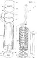
図1は、本発明の使用済み各燃料を輸送し貯蔵するためのコンテナの1つの態様の部分分解等角図である。
図1Aは、図1に示されるコンテナの部分を別の角度から見た等角図である。
図2Aは、図1に示されるコンテナの部分の部分分解等角図である。
図2B及び2Cは、図1に示されるコンテナの蓋の等角図である。
図3は、本発明に基いて形成されたバスケットの別の態様の部分分解等角図である。
図4Aは、図3に示されるバスケットの一部の部分分解等角図である。
図5A、5B、6A、及び6Bは、本発明に基いて形成された遮蔽プラグの断面図である。
図7は、図3に示されるバスケットのための有孔円板の平面図である。
図8Aは、本発明に基いて形成された、ジャケット及び中性子吸収層の部分の部分分解等角図である。
図8Bは、図3の組立てられたジャケット及び中性子吸収層の部分の等角図である。
図9Aは、図1に示される殻状体の部分の平面図である。
図9Bは、図9Aの線9B−9Bに沿う、図1の殻状体の断面図である。
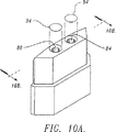
図10Aは、本発明に基いて形成された吸い上げ管を装着しているブロックの等角図である。
図10Bは、図10Aの線10A−10Aに沿う、図1の吸い上げ管装着ブロックの断面図である。
好ましい実施例の詳細な説明
破損燃料ロッド組立ての輸送及び貯蔵
図1は、全体的に参照番号20によって示される、本発明に基いて形成された輸送及び貯蔵組立て即ち缶組立てを示す。輸送及び貯蔵組立て20は、好ましくは、原子炉のための破損燃料ロッド組立ての貯蔵及び輸送のためのものである。しかし組立て20は破損していない核燃料ロッド組立ての輸送及び貯蔵にも使用され得ることが、当業者には容易に認識されるであろう。
有益な参考のために、輸送及び貯蔵組立て20は、2つの主要な構成要素、即ち全体的に参照番号22で示される缶及び全体的に参照番号24で示されるバスケット組立て、に分割されている。缶22はほぼ円筒形の中空の殻状体26を具備する。底部の蓋28は殻状体26の底部に蓋をして、基部を形成する。底部の蓋28は、殻状体26の内径にほぼ等しい直径を有するほぼ円形の断面を有する。底部の蓋28は、蓋28のほぼ平面の底部表面が殻状体26の底部縁部と同一平面になるまで、殻状体26の底部の端部に挿入される。底部の蓋28は、溶接のような従来の手段によって気密封止をするように殻状体26に固定される。
底部の蓋28が適所に溶接された後で、バスケット組立て24は殻状体26の上部の開放端部内へ挿入される。バスケット組立て24は、それを貫通して形成される複数のほぼ正方形の孔38を有する複数のほぼ円形の板36を具備する。板36はステンレス鋼から作られるのが好ましい。板36は、ほぼ均等な間隔で、各板36の外側縁部の周りに対称に形成された、4つのほぼ長方形の切欠き部40を具備する。長方形の切欠き部40は、各長方形の切欠き部の長い方の縁部が各板36の斜めの線に対してほぼ垂直になるように配置される。
好ましくは、板36は、8枚の細長い長方形の板即ち構造 的部材42によって互いに対して間隔を開けて軸方向にアラインして保持される。長方形の板42は、板36の各長方形の切欠き部の内側の長さにほぼ等しい幅を有する。従って、長方形の切欠き部40は長方形の板42を受容する。故に、一連の板36は、板36を間隔を開けて軸方向にアラインした配置でしっかりと保持するように、溶接のような従来の手段によって各長方形の板42に取付けられる。図示された実施例に於て、2枚の板42は、各長方形の切欠き部40が2枚の長方形の板42を受容するように互いに上部に重ねられる。代りに、各切欠き部40はより厚い厚さの1枚の長方形の板42を受容し得る。従って、代替実施例に於て、8枚の板よりは、むしろ4枚のより厚い長方形の板42が使用され得る。長方形の板42の端部は、図1Aに最も良く示されているように、最初と最後の板36を僅かに越えて突出している。
各板36は、ほぼ同じ配置の正方形の孔38を有する。従って、その板が、板42によって互いに対して軸方向にアラインさせられる時、孔38は複数の列に軸方向にアラインさせられる。全体的に図1の参照番号44で示される破損燃料コンテナは、各列内へ挿入される。
次ぎに図2Aでは、各破損燃料コンテナ44は、細長いほぼ正方形のスリーブ46を具備する。正方形のスリーブ46は、スリーブ46に溶接される正方形の蓋48によってその底部端部を蓋される。スリーブ46よりもかなり短い正方形のスリーブ50は、スリーブ46の上部端部に溶接される。正方形のスリーブ50は、スリーブ46の外側の横の寸法にほぼ等しい内側の横の寸法を有する。従って、長い方のスリーブ46の上部端部は短い方のスリーブ50の底部端部の中へ挿入されて、2本のスリーブは一緒に溶接される。スリーブ50の開放端部は破損燃料コンテナ44を覆うのに役立つ上部の蓋52を受容する。
蓋52は、図2Bに最も良く示されているように、唇状部54が短い方のスリーブ50の上方縁部に接触するまで、スリーブ50の中へ挿入される。(図2Bは、蓋52の下方表面へ向って見た斜視図である。)図2Bを参照すると、蓋52はほぼ正方形であり且つ短い方の正方形のスリーブ50の内側の横の寸法よりも僅かに短い横の寸法を有する、挿入可能な部分56を有する。従って、蓋52の挿入可能な部分56は、短い方のスリーブ内に摺動的に嵌り合う。蓋52は、短い方のスリーブ50内の適所への蓋52の摺動を容易にするために傾斜部分58を具備する。
図2Aに戻ると、蓋52は、蓋52の上方表面から放射状に突出している、中央に装着されるピントル即ち突出部60を具備する。ピントル60は従来の制御ロッドのクラスタ・ピントルにほぼ同じであるので、原子炉で利用できる標準的な燃料取扱いツールが、蓋52を短い方のスリーブ50から外したり、その中へ挿入するのに使用できる。
更に、蓋52は、図2Bに最も良く示されるように、蓋52の挿入可能な部分56を形成する夫々の垂直方向の壁に対称に形成される4つの長円形のスロット62を具備する。蓋52が短い方のスリーブ50内へ挿入されると、長円形のスロット62は、短い方のスリーブの夫々の垂直方向の壁に形成される対応する長円形のスロット63と整列する。従って蓋52が適所にある時に、取り扱いツールの尖った先がスロット62及び63を係合するのに使用され得るので、全破損燃料コンテナ44はツールで取り扱われ得る。更に、スロット62及び63は、短い方のスリーブ上の適所に蓋52を固定するためのピン(図示されていない)と選択自由に嵌り合わされ得る。
当業者によって良く知られているように、米国の原子炉で使用される燃料ロッドは、組立て状態で各個々の燃料ロッドを支持する内側格子を有する複数のほぼ正方形のブラケットによって半径方向に間隔を置いて保持される複数のロッドを具備する。正方形のスリーブ46の内側の横の寸法は、組立て状態で一緒に燃料ロッドを保持する正方形のブラケットと、正方形のスリーブ46の内側の壁との間で摺動的に嵌り合うような寸法にされることが好ましい。摺動的な嵌り合いとは、燃料ロッドを一緒に保持する正方形のブラケットとスリーブ46の内側の壁との間に小さな隙間があるような嵌り合いである。好ましくは、スリーブ46はステンレス鋼から作られるが、中性子が通り抜けるのをかなり妨げることができる十分に構造的に剛性の或る何等かの材料からも作られ得る。使用され得る他の物質はカドミウム、硼酸塩で処理されたステンレス鋼、硼酸塩で処理されたセラミック材料、及び“破損していない燃料ロッド組立ての輸送及び貯蔵”の討議で後に開示されるような、構造的部材間に挟まれる硼酸塩で処理されたアルミニウムの層を含む。
図1及び1Aに戻ると、破損燃料コンテナ44は軸方向にアラインされた孔38の各列内に長手方向に挿入される。正方形の孔38の内側の横の寸法は、摺動的に嵌り合うように正方形のスリーブ46の外側の横の寸法にほぼ等しい。破損燃料コンテナ44は各々、短い方のスリーブ50の底部表面が上方の板36の上方表面に接触するまで、軸方向にアラインした孔38の列の中に挿入される。従って、短い方のスリーブ50は、破損燃料コンテナ44が、孔38の軸方向にアラインされた列の中に挿入され得る深さを制限するために働く。
バスケット組立て24が殻状体26内へ挿入される時、バスケット組立て24は、図1Aに最も良く示されるように、最下部の板36の表面を越えて突き出している長方形の板42の底部端部の上に載る。殻状体内に挿入されると、バスケット組立て24は殻状体26の上部端部に溶接される一連の部材によって適所に封止される。適所に溶接される第1の部材は吸い上げ管装着ブロック64である。吸い上げ管(サイホン管、siphon tube)装着ブロック64は上部の板36の上方表面に隣接する殻状体26の内側に溶接される。
リング66が、吸い上げ管装置ブロック64の上方表面と下方表面との中間の高さで、殻状体26の内側周囲の周りに溶接される。リング66は吸い上げ管装着ブロックのための切取り部分を具備する。次ぎの部材は、有害な放射線の環境への漏れを防ぐための遮蔽プラグ即ち第1の遮蔽 プラグ68である。好ましくは、遮蔽プラグ68は、鋼鉄層72によってその下方と半径方向の側部上を取り囲まれている鉛の層70を具備する。鉛層70は、図6Aに示されるように、鋼鉄74のより薄い層によってその上方表面上を封止される。
遮蔽プラグ68は、下記の理由のために殻状体26に溶接されないのが好ましい。溶接プラグ68が適所にある時、それは殻状体26の内側からの有害な放射線の漏れを遮蔽する。従って、人が何等かの放射線に晒されるのを最低限に維持するためには、殻状体26が最低の時間で封止される必要がある。故に、遮蔽プラグ68は適所に下ろされ、内側上部の被覆板80が遮蔽プラグ68の上方の適所に溶接される。内側上部の被覆板80はステンレス鋼のみから作られる時、鉛を溶かして、溶接の汚染をもたらす危険性がないので、単純な溶接が要求される。対照的に、遮蔽プラグ68の溶接はその様な危険性をもたらすであろう。内側上部の被覆板80の周囲の縁部は、図1に示される吸い上げ管装着ブロック64を受容するほぼ長方形の切欠き部82を具備する。
貯蔵及び輸送組立て20を構成する材料の種類に関して、殻状体26はステンレス鋼から作られるのが好ましい。材料の他の種類、例えば炭素鋼、も使用され得るが、ステンレス鋼は、その構造的強度、耐腐食力、中性子の通過をかなり妨害する能力、及び引き続いて熱処理が必要な、延性を失うことの無い溶接に耐える能力のために好ましい。更に、一緒に溶接される全ての構成要素は、同じ種類の材料を具備することが好ましく、これは異なった熱膨張率のような、異なった材料の特性を有する異なった材料による複雑化を避ける。故に、吸い上げ管装着ブロック64は、リング66、内側上部の被覆板80、等のような、殻状体26に溶接される如何なる部材も、ステンレス鋼から作られるのが好ましい。対照的に、円形の板36及び相互連結する長方形の板42は、高強度の炭素鋼から作られて、高強度の支持枠とされるのが好ましい。
遮蔽プラグ68は殻状体26に溶接されないので、遮蔽プラグ68を構成する鋼鉄層72及び74は、炭素鋼のような、ステンレス鋼よりも安い別の材料から作られ得る。代りに、遮蔽プラグは、図5Aの遮蔽プラグ即ち第2の遮蔽プ ラグ76で示される中実の鋼鉄から作られ得る。それにも関わらず、鉛は鋼鉄よりも高い遮蔽能力を有するので、中実の鋼鉄の遮蔽プラグは内部に鉛層70を持つ遮蔽プラグ68に較べてより厚い。
図1を参照すると、遮蔽プラグ68の周囲の縁部には、遮蔽プラグ68が吸い上げ管装着ブロック64の上部を越えて摺動するように、ほぼ長方形の切欠き部78が具備される。前述の状態に於て、遮蔽プラグ68はリング66及び吸い上げ管装着ブロック64の、図10Aに示される段状部79によって支持される。遮蔽プラグ68がリング66及び段状部79上の適所にある時、遮蔽プラグ68の下方表面と各破損燃料コンテナ44との間の隙間は十分に小さくて、各破損燃料コンテナからの上部の蓋52の変位を防ぐ。
通常、燃料ロッド組立ては、原子炉の燃料プール内で貯蔵組立て20へ入れられる。従って、燃料ロッド組立ては水中で貯蔵組立て20へ入れられる。水中で入れられると、輸送及び貯蔵組立て20が燃料プールから取り出された後で、缶22から水を取り出すことが必要である。この目的のために、吸い上げ管構造が本発明に基いて備付けられる。吸い上げ管構造は、内側上部の被覆板80に隣接して、殻状体26の上部部分に取付けられる吸い上げ管装着ブロック64を具備する。図10A及び10Bに示される、2本の通路84及び86は、吸い上げ管装着ブロック64を長手方向に通り抜けて形成される。経路84及び86は真っ直ぐな貫通通路はなくて、直角部を有するので、放射能物質の流出を防ぎ且つ有害な放射線の漏れを最小にする。更に、通路86はT型部分を具備し、“T"の一方の枝部は塞がれている。このT型部分は、通路86及び84がボーリング或いはドリルによって形成されるのが好ましいので、ただ製造を容易にする目的のために具備される。
内側上部の被覆板80が適所に溶接されると、唯一の通路である吸い上げ管装着ブロック64内の貫通通路84及び86を備えた、気密の内部空洞が殻状体26の内側に形成される。吸い上げ管構造は、吸い上げ管装着ブロック64内の通路86に連結される吸い上げ管88を具備する。図1に見られ得るように、吸い上げ管88は各板36内に形成されるほぼ円形の孔90を通り抜ける。バスケット組立て24の拡大図は、吸い上げ管88の拡大図と共に、図1Aに示される。
前述の吸い上げ管即ちサイホン管の構造は、下記のやり方で缶22から液体を除去するのに使用される。空気のホース(図示されていない)は、吸い上げ管装着ブロック64の通路84に連結される。好ましくは、通路84はねじが切られていて、空気ホースが素早く通路に連結され且つ外され得るような、“即時−着脱”取付け具で嵌め合わされる。それから圧縮空気、或いは別の圧縮ガスが通路 84を通って殻状体26内に押し込まれ、缶内の如何なる液体も押されて吸い上げ管88及び通路86を通って排出される。ほぼ全ての液体が殻状体26から押し出されるのを確実にするために、図6Bに示されるように、端ぐり機で拡げた孔92が底部の蓋28の上方表面内に形成される。吸い上げ管88の底部端部は、底部の蓋28の上方表面の下で端ぐり機で拡げた孔92の中へ延在して、殻状体22内のほぼ全ての液体が吸い上げ管を通って押し出され得るのを確実にする。
ほぼ全ての液体が殻状体26から押し出されると、あらゆる残りの液体が蒸発してしまうまで、圧縮空気或いは他の圧縮ガスが続いて通路84を通って、吸い上げ管88から及び通路86から押し込まれ得る。それから、図10Aに示される端部のキャップ94が通路84及び86の各々の上に溶接されて、殻状体26の内側に気密の封止部を形成する。それから殻状部26は、図1に示されるように殻状体26の内側の周囲の周りにほぼ円形の外側上部の被覆板96を溶接することによって更に封止される。図1に示されるように、外側上部の被覆板96は吸い上げ管装着ブロック64の上方表面及び内側上部被覆板80の上で溶接される。
当業者によって容易に認識され得るように、缶22はかなりの量の鋼鉄を含み、重い。したがって、缶22は、図9A及び9Bに示されるように、道具による缶の取扱いを容易にするために釣り手98を具備し得る。好ましくは、4つの釣り手98が、殻状体26の内側周囲の周りにほぼ同じ間隔と高さで対称に取付けられる。図9A及び9Bに於て、釣り手98はリング66の内側表面に半径方向に溶接される。通常、燃料の輸送及び貯蔵組立て20が移動のために使用される時、この組立てが樽状容器(図示されていない)の中に配置される。従って、釣り手98は樽状容器への缶22の挿入を容易にする。
樽状容器は、有害な放射線からの環境の追加的な維持及び保護を行い、樽状容器は道具による樽状容器の取扱いを容易にする釣りトラニオンを具備する。そのような樽状容器の1つは、使用済み核燃料の輸送及び貯蔵用樽状容器(Transportation and Storage Cask for Spent Nuclear Fuels)という名称で、1993年10月8日に出願され、カイルB.ジョーンズ(Kyle B.Jones)氏、ロバートA.レナート(Robert A.Lehnert)氏、ロバートD.キン(Robert D.Quinn)氏、スティーブンE.シスリー(Steven E.Sisley)氏、及びチャールズJ.テムス(Charles J.Temus)氏によって米国出願番号第08/131,973号明細書に譲渡された出願に於て開示されている。上記で明示された出願の内容は、ここで参考文献として明白に組み入れられる。
樽状容器/缶の組合わせ体が車両で輸送される時、通常それは更なる安全のための衝撃リミッタ内に配置される。衝撃リミッタは輸送中に例えば車両事故の時に生じ得る衝撃を減衰して、損傷から樽状容器/缶の組合わせ体を、及び有害な放射線の漏れから環境を保護する。その様な衝撃リミッタ(Impact Limiter for Spent Nuclear Fuel Transportation Cask)という名称で、1993年10月8日に出願され、ロバートA.ジョンソン(Robert A.Johnson)氏、イアンD.マッキン(Ian D.McInnes)氏、ロバートD.キン氏、及びチャールズJ.テムス氏によって米国出願番号第08/131,972号明細書に譲渡された出願に於て開示されている。上記で明示された出願の内容は、ここで参考文献として明白に組み入れられる。
底部の被覆板28は、図6Bに示されるサンドイッチ状の層構造である。最上部の層108は鋼鉄であり、中間の層108は鉛であり、鋼鉄の底部の層112が次ぎにくる。一般的に、上部の鋼鉄の層108は、最初に殻状体26の内側表面に溶接される。続いて、鉛が底部の鋼鉄層112上に注がれて鉛の層110を形成する。それから層110及び112が殻状体26に挿入され、層112はそれに溶接される。底部の蓋が挿入される時、殻には燃料ロッド組立てが入っていないので、底部の蓋28の中に組み入れられる鉛と共に溶接が行われ得る。こうして、有害な放射線を受ける危険性と時間の消費の無い、遮蔽プラグ68と対照的に溶接による鉛の汚染の危険性を減じた、溶接作業が行われ得る。
代りに、底部の蓋28は図5Bに示されるような全て鋼鉄の層から構成され得る。しかし、鋼鉄は鉛の持つ遮蔽能力を有さず、従って図5Bの底部の蓋28は図6Aの底部の蓋28に較べて厚い。図5Bに於て、第1の層116は殻状体26の内側表面に溶接するためにステンレス鋼の層であることが好ましい。次ぎの層118は、遮蔽をするためのより値段の安い炭素鋼であり、それは殻状体26とは異なる材料であるので、殻状体26に溶接されない。最上部の層は別のステンレス鋼の層120であり、これは殻状体26に溶接される。
最後に、底部の蓋28は、図1、5B、及び6Bに示すラム係合のリング114を具備する。ラム係合のリング114は、その長手方向の軸に沿って缶22を押したり引いたりするための水圧ラム(図示されていない)と噛合って、例えば、それを貯蔵場に挿入したりそこから取出したりする。
バスケット組立て24が缶内に挿入される時、缶22に対するバスケット組立ての回転は、図9A及び9Bに示される、殻状体26の内側半径方向の表面から半径方向に突出している2つの長方形のキー100、及びリング66によって防がれる。好ましくはキー100は、ほぼ等しい高さで且つ殻状体26の内側周囲の周りで180゜の間隔を置いて、殻状体26の内側表面に半径方向に溶接される。半径方向に突出したキー100は、図1Aに示されるように、バスケット組立て24の最上部の板36の外側縁部に形成される2つの長方形のスロット102によって受容される。図1Aに於いて、一方のスロット102だけが見ることができ、他方のスロットは、スロット102から約180゜の間隔を置いている。好ましくは、バスケット組立て24が最初に殻状体26の中へ挿入され、それからキー100がスロット102内に挿入され、殻状体26に溶接される。従って、キー100は最上部の板36のスロット102を支持することによって、缶22に対するバスケット組立て24の回転を防ぐのに役立つ。
先に記されたように、輸送及び貯蔵組立て20は破損燃料ロッド組立てで使用するためのものであることが好ましい。等業者に良く知られているように、燃料ロッドは、核分裂物質を有する複数のペレットを取り囲む、クラッド層と呼ばれる、中空の管を具備する。ロッド、それ自身は、先に説明された何本かのロッドの集合体で配置される。或る場合に於て、7ラッド層は損傷し、破損燃料ロッドと呼ばれる。破損燃料ロッドは、核分裂物質をロッドから零し得る。更に或る場合に於て、燃料の核反応中にペレットは、破損燃料ロッドから容易に零れ得る砂粒大の粒子に崩壊する。
発明の背景に於て記されたように、使用済み燃料の輸送に関する重要な部分は臨界状態になることを避けることである。これは、臨界点に至る中性子の増殖の可能性が殆ど無くなるように、各組立て間の間隔を最小にするように使用済み燃料ロッド組立てを慎重に配置することによって具現される。しかし、破損燃料ロッド組立ての場合、核分裂物質は破損ロッドから零れて、別の核分裂物質の十分近くに集まって臨界状態に達し得る。
しかし、貯蔵及び輸送組立て20は、或る破損燃料ロッド組立てからのほぼ全ての核分裂物質が単一の破損燃料コンテナ44に閉じ込められたまま保たれるのを確実にすることによって上述の問題に対処する。この目的のために、上部の蓋52及び底部の蓋48は各々、図2B及び2Cに最も良く示されるように、4本のふるいのある通路104を具備する。図2B及び2Cに示されるように、この通路は、缶22の上部及び底部にほぼ平行する上部の蓋52及び底部の蓋48の表面に配置される。(図2B及び2Cは、上部の蓋52及び底部の蓋48の下方表面へ向って見た、斜視図である。)
液体が缶22から取り除かれる時、破損燃料コンテナ44内の如何なる液体も、底蓋48の4つのふるいのある通路104を通って排出され得る。しかし、通路104のふるいは十分に細かくて破損燃料ロッドからの如何なる漏出核分裂物質もふるいのある通路104を通り抜けるのを妨げられる。更に、底蓋48の下方表面上の、図2Cに示される、蓋48の各縁部に沿う4つの長方形の垂直方向の突出部106は、ある最小の間隔がふるいのある通路104と缶22の底蓋28の上方表面との間に維持されることを確実にする。代りに、単一の正方形の垂直方向の突出部が、蓋48の底部表面上の中央で使用され得る。こうして、破損燃料コンテナ44内の液体が通路104から排出されるように十分な間隔が維持される。
更に、破損燃料コンテナ44内の液体が排出されて、破損燃料コンテナからの液体の排出を容易になると、上蓋52のふるいのある通路104は、空気或いは他のガスを破損燃料コンテナ44の内部に入れることができる。先に記されたように、各破損燃料コンテナ44と遮蔽プラグ68との間の隙間は、遮蔽プラグ68が適所にある時には、上蓋52が各破損燃料コンテナから外れるのを妨げるようなものである。それにも関わらず、ふるいのある通路104が形成される各上蓋52の表面は、図2A及び2Bに見られるように、唇状部54の下で引っ込まされている。従って、上述の構造は、液体が排出される時に、空気或いは他のガスが各破損燃料コンテナ44の内部に入ることができるように、各上蓋52のふるいのある通路104と遮蔽プラグ68の下方表面との間の十分な空間を確保する。更に、蓋52のふるいのある通路104は、コンテナ44が上蓋52の上方表面は水平でないような、或いは底蓋48の上方表面よりも高さが低くなるような位置に配置されても、核分裂物質がコンテナから漏出し得ないということを確実にする。
損傷していない燃料ロッド組立ての輸送及び貯蔵
バスケット組立て24は好ましくは破損燃料ロッド組立てに対するものであるが、図3に示されるバスケット組立て122(全体的に参照番号122で指示される)は、損傷していない燃料ロッド組立ての輸送及び貯蔵のために設計されたものである。バスケット組立て122は、図1及び1Aのバスケット組立て24が挿入されるのと同じように、図1、9A、及び9Bに示される、缶22内へ挿入される。更に、バスケット組立て122を缶22に封止するやり方は、バスケット組立て24に関して説明されたのと同じやり方である。
バスケット組立て122は、貫通して形成される複数のほぼ正方形の孔126を有する複数のほぼ円形の板124を具備する。1枚の板124の上面図は図7に示される。板124は、各板を貫通している4本のロッド128によって互いに対して間隔を置き軸方向にアラインして維持される。各ロッド128は、各板124に形成される4つの穴130の1つを通り抜ける。ロッド128は各板124に溶接されて、ロッド128に対する板124の移動を防ぐ。板124は高い強度の炭素鋼から作られるのが好ましく、相互連結しているロッド128はステンレス鋼から作られるのが好ましい。穴130は好ましくは挿入物を具備して、ステンレス鋼を高い強度の炭素鋼に溶接することによって生じる紛糾を緩和する。
各板124は、ほぼ同じ配置の正方形の孔126を具備する。従って、板124がロッド128によって互いに対して軸方向にアラインされる時、孔126は複数の列にアラインされる。図3に於て全体的に参照番号132によって示される誘導スリーブ組立て132は、各列内に挿入される。各ロッド128の上部及び底部端部は、各誘導スリーブ組立て132の上部及び底部の端部を越えて延在する。従って、バスケット組立て122が殻状体26内に挿入される時、ロッド128の底部端部は底蓋28の上方表面と接触して、誘導スリーブ組立て132の底部端部と底蓋28との間の間隔を維持する。加えて、遮蔽プラグ68がバスケット組立て122の上部に配置される時、殻状体26内では、ロッド128の上部端部、及びリング66は誘導スリーブ組立て132の上部端部の上方で遮蔽プラグを支持する。
誘導スリーブ組立て132の一部分の拡大図は図8Aに示される。図8Aの組立ての組立てられた所が図8Bに示される。各誘導スリーブ組立て132は、図8Aに示される細長いほぼ正方形の内側誘導スリーブ134を具備する。内側誘導スリーブ134は好ましくはステンレス鋼から作られ、軸方向にアラインされる正方形の孔126の各列内に挿入されて、各板124を貫通する。各誘導スリーブ134の上部端部はフレア部140を具備して、下記で説明される燃料ロッド組立ての挿入を容易にする。
中性子吸収材料或いはアルミニウムの長方形の薄板136は、長方形の薄板136の場所に応じて、内側誘導スリーブ134の各外側面に隣接して配置される。図4Aに示されるように、長方形の薄板136が、軸方向にアラインされる孔126の別の別に直接に面する場所A(図7)にある時、長方形の薄板は中性子吸収材料から作られる。しかし、長方形の薄板136が軸方向にアラインされる孔126の別の列に直接面しない位置、例えば図7の位置B、にあるならば、長方形の薄板は中性子吸収材料から作られる必要はなくて、アルミニウム、鋼鉄、或いは他の構造的支持材料から作られ得る。
長方形の薄板が中性子吸収材料から作られるならば、材料は硼酸塩で処理されたアルミニウムであるのが好ましい。しかし、カドミウム、硼酸塩で処理されたステンレス鋼、硼酸塩で処理されたセラミック材料、等のような、何れの中性子吸収材料も使用され得る。4枚のその様な長方形の薄板136は軸方向にアラインされる孔126の各列内に挿入され、その結果1枚の長方形の薄板136が各内側の誘導スリーブ134の各外側表面と各板124との間に配置される。
一連のより短い誘導スリーブ138は、長方形の薄板136及び内側誘導スリーブ134を取り囲む。外側誘導スリーブ138は、内側誘導スリーブ134と隣接する対の板124との間に露出される、対応する長方形の薄板136を取り囲む。従って、外側誘導スリーブ138は隣接する対の板124の間の色々な間隔に対して色々な長さになり得る。各外側誘導スリーブ138の端部は、図4Aで最も良く見られるように、各板124の表面を支持するようにフレア部140を具備する。
上部及び底部の板124を越えて突出している各内側誘導スリーブ134の端部は、外側誘導スリーブ138によって取り囲まれない。各内側誘導スリーブの上部突出端部は、好ましくは鋼鉄から作られる終端キャップ142によって取り囲まれる。各内側誘導スリーブの底部端部は、図4Aに示される通りである。
図4Aでよく見られるように、各長方形の薄板136の底部端部が、L型ブラケット即ち保持具148を受容するための長方形の切欠き部146を具備する。各ブラケット148は、内側誘導スリーブ134及び底板124へ固定され、板124に対する内側誘導スリーブ134及び長方形の薄板136の垂直方向の移動を防ぐ。ブラケット148は、溶接、ねじ留め、或いは何等かの他の公知のやり方によって内側誘導スリーブ134及び底板124に固定され得る。先に記されたように、一緒に溶接される部材は、色々な材料の特性を有する部材に伴う紛糾を避けるように同一の材料であることが好ましい。内側誘導スリーブ134は、好ましくはステンレス鋼から作られるのが好ましいので、ブラケット148はステンレス鋼から作られ、内側誘導スリーブに溶接され、好ましくは高い強度の炭素鋼から作られる底板124にねじ留めされ得る。
先に記されたように、バスケット組立て122は、バスケット組立て24の破損燃料ロッド組立てに対するのと同じやり方で、缶22内へ挿入される。損傷していない燃料ロッド組立てのバスケット組立て122が缶22内に挿入されると、損傷していない燃料ロッド組立ては各誘導スリーブ組立て132に挿入され、缶22は先に説明されたように封止され、そして吸い上げられ得る。
先に説明されたように、“A"の位置で中性子吸収層(長方形の薄板136)を具備する、誘導スリーブ組立て132の多層構造は、中性子が臨界レベルに増殖する危険性に対する更なる安全要因を与える。従って、コンテナ22と組合わせのバスケット組立て122は、上述で説明された樽内へ挿入され得て、樽/缶の組合せ体は公衆に影響を与え得る地域を横切って燃料ロッド組立てを輸送するのに使用され得る。
燃料のみのロッド組立て、対、制御要素を有する燃料ロ ッド組立て
当業者に良く知られているように、燃料のみを含む燃料ロッド組立ては、制御要素を有する燃料ロッド組立てよりも長さが短い。本発明によると、缶22及びバスケット組立て122は、缶22の外側寸法を何等変更すること無しに、何れの型の燃料ロッド組立てででも使用され得る。
上述のことは、夫々、図5A及び6Aに示される2つの別々の遮蔽プラグ76及び68の使用によって具現される。缶22及びバスケット組立て122が、燃料のみを含む、より短い燃料ロッド組立てで使用される時、全て鋼鉄の遮蔽プラグ76が使用される。全て鋼鉄の遮蔽プラグ76は、同じく鉛層を具備する遮蔽プラグ68よりも厚い。従って、より厚い遮蔽プラグ76は缶22内に更に垂直方向の空間を占めるので、燃料のみの燃料ロッド組立てのより短い長さを償う。
より厚い遮蔽プラグ76は先に説明された鋼鉄層116、118、及び120のみを具備する、図5Bに示される、より厚い底蓋28と共に使用されるのが好ましい。全て鋼鉄の層を具備する厚い底蓋28は、図6Bに示される、鉛層110を具備する、より薄い底蓋28に較べて缶22内でより大きな垂直方向の空間を占める。
バスケット組立て122が制御要素を具備するより長い燃料ロッド組立てで使用される時、鉛層70を具備するより薄い遮蔽プラグ68が使用される。鉛はより大きい遮蔽力を有するので、より薄い遮蔽プラグ68は全て鋼鉄の遮蔽プラグ76と比較してかなり薄いが、鉛のないプラグと同じ遮蔽力を持つ。鉛層110を具備するより薄い底蓋28は、より薄い遮蔽プラグ68と組合わせて使用されるのが好ましい。
より厚い遮蔽プラグ76を使用することよりも、スペーサが各誘導スリーブ組立て132の中へ挿入され得て、より短い燃料ロッド組立てを償うであろう。更に、そのようなスペーサは、同じバスケット組立て内でより長い燃料ロッド組立てとより短い燃料ロッド組立てを混ぜるのに使用され得る。最後に、そのようなスペーサは色々な長さの破損燃料ロッド組立てのためのバスケット組立てでも使用され得る。
本発明の好ましい実施例が例示され且つ開示されたが、本発明の意図及び範囲から逸脱することなしに、その中で色々な変更が行われ得るということが認識されるであろう。 Field of Invention
The present invention relates to a container for transport and storage of spent nuclear fuel, in particular a container for transport of spent nuclear fuel across an area that can affect the public.
Background of the invention
In nuclear reactors, fission material has been used gradually and has to be removed. Since spent fuel is highly radioactive and contains fission phenomena due to products that generate large amounts of heat, spent fuel is usually temporarily stored in a spent fuel pool in a nuclear reactor. A spent fuel pool is a pool of water sufficient to prevent the leakage of harmful radiation and to absorb and release the heat generated by the decaying fissile material. Alternatively, spent fuel can be temporarily stored in the hot cell. That is, it is a tightly shielded structure that has the ability to prevent harmful radiation leakage while absorbing and dissipating heat generated by spent fuel.
In general, the storage space of a nuclear reactor spent fuel pool or in its hot cell is limited. Thus, spent fuel must be moved to a storage location to make room for the next spent fuel. In some cases, it is required to shut down the reactor and remove all fission material, in which case all the fission material must be transferred to a storage site.
There are two important issues regarding the transport of spent fuel. The most difficult problem is the transportation of spent fuel, including broken fuel rod assembly. In general, nuclear fuel consists of many small pellets that are inserted into hollow rods. In some cases, the rod may be damaged and some nuclear fuel pellets may fall out. These damaged rods are known as broken fuel rods. Furthermore, in some cases, during the nuclear reaction of pellet fuel, it breaks down into sand-sized particles that can easily spill from the broken fuel rod. The fuel rods themselves are grouped together into an assembly that includes several fuel rods. Accordingly, a fuel rod assembly that includes a broken fuel rod is referred to as a broken fuel rod assembly.
An important part of transporting and storing spent fuel is to avoid becoming critical. This is accomplished by careful placement of the spent fuel rod assembly, so that there is little potential for neutron growth to the critical point. However, in the case of a broken fuel rod assembly, the fission material can spill out of the broken rod, possibly gathering close enough to other fission materials to reach a critical state.
One attempt to address the aforementioned problem is to simply accumulate a broken fuel rod assembly in the spent fuel pool or hot cell of the reactor indefinitely. However, the problem with accumulating broken fuel rod assemblies indefinitely is that the spent fuel pool or hot cell storage space of the reactor is limited, and in some cases the reactor is shut down completely. It is required to remove all fission materials, including those contained in broken fuel rod assemblies.
Another attempt is to transport broken fuel rods in a fuel shipping container designed for undamaged fuel rod assembly. However, this approach solution requires transporting significantly fewer broken fuel rod assemblies per container compared to the number of undamaged fuel rod assemblies that can be transported in the same container. By transporting fairly few broken fuel rod assemblies, even if some fission material spills from the broken fuel rod and accumulates near other fission material in the container, the fission material in the entire container becomes critical Not enough to cause such a serious danger. However, the problem with this solution is the waste of resources due to the fact that only a few broken fuel rod assemblies can be transported per container compared to the number of undamaged fuel rod assemblies that can be transported in the same container. is there.
Another attempted solution is to transport the broken fuel rod assembly in a fuel transport container designed for the transport of crushed fissile material. That is, the fission material is not in the shape of a rod but in the shape of a small piece. Therefore, the broken fuel rod is crushed into a crushed stone and placed in the container. However, the problem with this solution is that this method is not effective for three main reasons. First, the broken fuel rod assembly is broken. Second, such containers can only transport relatively few broken fuel rod assemblies. Finally, shipping containers are designed for transport only, not storage. Thus, if the fissile material is transported to another location, the container is unloaded in the fuel pool or hot cell and another means must be taken to store the fissile material.
The present invention solves the aforementioned problems and provides an apparatus for transporting and storing damaged fuel rod assemblies other than spent fuel pools or hot cells in storage.
Another important issue with transporting spent nuclear fuel is that severe safety conditions are imposed even on containers used to transport fuel rod assemblies that are not damaged by US law. . Relevant laws impose rather stringent conditions on the transport of spent nuclear fuel across areas that can affect the public, as opposed to those areas that cannot affect the public.
A container for the transport of spent fuel to an area that can affect the current public is a cask with individual compartments. The fuel rod assembly is placed in individual compartments within the barrel in a spent fuel pool or hot cell. The purpose of the individual compartments of each barrel is to ensure that there is sufficient space between adjacent fuel rod assemblies to avoid any danger of becoming critical. The fuel rod assembly is placed in a barrel in a spent fuel pool or hot cell. Upon reaching the storage location, the fuel rod assembly must be removed from the barrel in the spent fuel pool or hot cell.
In contrast, shipping containers for spent fuel to areas that cannot affect the current public are typically sealed canisters placed in barrels. The fuel rod assembly is placed in a separate compartment within the can in a spent fuel pool or hot cell. The can is then sealed and placed in a barrel. When the keg / can assembly reaches the storage, the cans can be removed from the keg and stored and the keg can be reused. This is a much more efficient method.
Nevertheless, this barrel / can method cannot be used to transport within an area that could affect the public because they do not meet the requirements imposed by US law. Accordingly, there is a need for an invention for the transportation and storage of broken fuel rod assemblies and for barrels / cans that transport and store spent fuel across an area that may affect the public. The present invention provides a solution where barrels / cans can be used, and can be used with existing barrels to provide much greater efficiency for transportation on public streets and storage of spent nuclear fuel. Give a plan.
Summary of the Invention
The present invention, in one aspect, relates to a container for containing a structurally damaged nuclear fuel assembly and subsequently storing and transporting the nuclear fuel assembly. The nuclear fuel assembly contains fission material and is received by the container within the fuel pool. Container is an elongated container that forms an enclosureIe sleeveIt comprises. The container has an open end for receiving a structurally damaged nuclear fuel assembly. Perfect fitIe lidIs provided to close the open end of the container. Furthermore, a discharge channel is formed in the container so that liquid can be discharged from the inside of the container to the outside of the container. In addition, the discharge path includes a restrictor that prevents fissile material from passing through the discharge path. The container may also include an outer protrusion for receiving a fuel handling tool used to handle the container.
In another aspect, the present invention is a can for receiving a structurally damaged nuclear fuel assembly and subsequently storing and transporting the nuclear fuel assembly.AssemblingAbout. The nuclear fuel assembly contains fission material and cans in the fuel poolAssemblingIs accepted by. canAssemblingComprises a basket assembly having a plurality of perforated plates and a structural member interconnected to the perforated plates.
The structural members are spaced and hold the plates so that the holes in each plate are axially aligned in a plurality of rows. The basket assembly is received in an outer shell that forms an enclosed opening at one end. The basket assembly is surrounded by shells and oriented so that the longitudinal axis of each row is substantially parallel to the longitudinal axis of the shells.
Containers are inserted into each row of axially aligned holes. Each container is for containing a damaged nuclear fuel assembly and comprises an elongated container forming an enclosure with an open end. The structurally damaged nuclear fuel assembly is inserted into the container through the open end of the enclosure.
Alternatively, it is adapted to fit with the open end of the container and substantially closes the open end of the container. Furthermore, a discharge channel is formed in each container for discharging liquid from the container. The discharge channel includes a restrictor that prevents the passage of fissile material. A lid that fits the open end of the shellThat is, the coated plateIs also provided, thereby closing the open end of the shell. In addition, outside each container may be provided with a protrusion for receiving a fuel handling tool for inserting and removing the container into and from the can.
In another aspect, the invention comprises a basket assembly and a can for storing and transporting a nuclear fuel assembly. The basket assembly also includes a plurality of perforated plates and structural members that interconnect the perforated plates. The structural members hold the plates so that they are spaced apart and the holes in each plate are aligned in multiple rows in the axial direction.
An outer shell that forms an enclosure opening at one end receives and surrounds the basket assembly. The basket assembly is oriented within the shell such that the longitudinal axis of each row is substantially parallel to the longitudinal axis of the shell. Multiple induction sleevesAssemblingThe basket assembly includes a guide sleeveAssemblingCorresponds to the number of rows of holes in the plate aligned in the axial direction.
Each induction sleeveAssemblingHas a longitudinal axis approximately coincident with the corresponding column;Inner induction sleeve,Inner induction ReeveA neutron absorbing layer supported by, andInner invitation Lead sleeveOpposite of~ sideStructurally supports the side of the neutron absorption layerOuter induction sleeveIt comprises. A lid that fits with the open end of the shell and closes the open end of the shellThat is, the coated plateIs provided. Preferably,Inner induction sleeveComprises a hollow steel jacket that is inserted into each row of axially aligned holes. Other features of the present invention will become apparent from the following detailed description.
[Brief description of the drawings]
The foregoing aspects and many of the attendant advantages of the present invention will be more readily appreciated when the accompanying drawings are referenced and better understood with regard to the following detailed description.
FIG. 1 is a partially exploded isometric view of one embodiment of a container for transporting and storing each spent fuel of the present invention.
FIG. 1A is an isometric view of the portion of the container shown in FIG. 1 from another angle.
2A is a partially exploded isometric view of the portion of the container shown in FIG.
2B and 2C are isometric views of the lid of the container shown in FIG.
FIG. 3 is a partially exploded isometric view of another embodiment of a basket formed in accordance with the present invention.
FIG. 4A is a partially exploded isometric view of a portion of the basket shown in FIG.
5A, 5B, 6A, and 6B are cross-sectional views of shielding plugs formed in accordance with the present invention.
FIG. 7 is a plan view of a perforated disk for the basket shown in FIG.
FIG. 8A is a partially exploded isometric view of the jacket and neutron absorbing layer portions formed in accordance with the present invention.
8B is an isometric view of the assembled jacket and neutron absorbing layer portion of FIG.
FIG. 9A is a plan view of a portion of the shell-like body shown in FIG.
9B is a cross-sectional view of the shell of FIG. 1 taken along line 9B-9B of FIG. 9A.
FIG. 10A is an isometric view of a block fitted with a wicking tube formed in accordance with the present invention.
10B is a cross-sectional view of the wick tube mounting block of FIG. 1 taken along line 10A-10A of FIG. 10A.
Detailed Description of the Preferred Embodiment
Transportation and storage of broken fuel rod assemblies
FIG. 1 shows a transport and storage assembly formed in accordance with the present invention, generally designated by the reference numeral 20.That is, can assemblyIndicates. The transport and storage assembly 20 is preferably for storage and transport of a broken fuel rod assembly for a nuclear reactor. However, those skilled in the art will readily recognize that the assembly 20 can also be used to transport and store undamaged nuclear fuel rod assemblies.
For useful reference, the transport and storage assembly 20 is divided into two main components: a can generally indicated by reference numeral 22 and a basket assembly generally indicated by
After the
Preferably, the
Each
Next, in FIG. 2A, each damaged
The
Returning to FIG. 2A, the
In addition, the
As is well known by those skilled in the art, fuel rods used in US nuclear reactors are radially spaced by a plurality of generally square brackets having an inner grid that supports each individual fuel rod in the assembled state. It comprises a plurality of rods held in place. The inner lateral dimension of the
Returning to FIGS. 1 and 1A, a
When the
A
The shielding
With respect to the types of materials that make up the storage and transport assembly 20, the
Since the shielding
Referring to FIG. 1, a substantially
Typically, the fuel rod assembly is placed into the storage assembly 20 within the reactor fuel pool. Accordingly, the fuel rod assembly is placed into the storage assembly 20 in water. When submerged, it is necessary to remove water from the can 22 after the transport and storage assembly 20 has been removed from the fuel pool. For this purpose, a suction tube structure is provided according to the invention. The suction tube structure comprises a suction tube mounting block 64 attached to the upper portion of the
When the inner
Said suction tubeSiphon tubeThis structure is used to remove liquid from the can 22 in the following manner. An air hose (not shown) is connected to the
When almost all of the liquid is pushed out of the
As can be easily recognized by those skilled in the art, can 22 contains a significant amount of steel and is heavy. Thus, the can 22 may include a
The barrels provide additional maintenance and protection of the environment from harmful radiation, and the barrels include a fishing trunnion that facilitates handling of the barrels by tools. One such barrel is filed on October 8, 1993 under the name Transport and Storage Cask for Spent Nuclear Fuels, and Kyle B. Jones. (Kyle B. Jones), Robert A. Lehnert, Robert D. Quinn, Steven E. Sisley, and Charles J. Thames ( Charles J. Temus) in an application assigned to US application Ser. No. 08 / 131,973. The contents of the applications specified above are hereby expressly incorporated by reference.
When a barrel / can combination is transported in a vehicle, it is usually placed in an impact limiter for additional safety. The impact limiter attenuates the impact that may occur during transport, for example in the event of a vehicle accident, protecting the barrel / can combination from damage and the environment from harmful radiation leaks. Such an impact limiter (Impact Limiter for Spent Nuclear Fuel Transportation Cask) was filed on October 8, 1993, and Robert A. Johnson, Ian D. McInnes ), Robert D. Kin, and Charles J. Thames in the application assigned to US application Ser. No. 08 / 131,972. The contents of the applications specified above are hereby expressly incorporated by reference.
The
Alternatively, the
Finally, the
When the
As noted above, the transport and storage assembly 20 is preferably for use with a broken fuel rod assembly. As is well known to those skilled in the art, the fuel rod comprises a hollow tube, called a cladding layer, surrounding a plurality of pellets with fission material. The rods themselves are arranged in an assembly of several rods as described above. In some cases, the 7 rad layer is damaged and is called a broken fuel rod. A broken fuel rod can flush fissile material from the rod. Further, in some cases, during the nuclear reaction of the fuel, the pellets collapse into sand-sized particles that can easily spill from the broken fuel rod.
As noted in the background of the invention, an important part of transporting spent fuel is to avoid becoming critical. This is embodied by careful placement of the spent fuel rod assembly to minimize the spacing between each assembly so that there is almost no possibility of neutron growth to the critical point. However, in the case of a broken fuel rod assembly, the fission material can spill from the broken rod and gather close enough to another fission material to reach a critical state.
However, the storage and transport assembly 20 addresses the above problem by ensuring that almost all of the fissile material from a broken fuel rod assembly remains confined in a single damaged
When liquid is removed from the can 22, any liquid in the
In addition, when the liquid in the damaged
Transportation and storage of undamaged fuel rod assemblies
Although
The
Each
An enlarged view of a portion of the
A rectangular
If the rectangular sheet is made of a neutron absorbing material, the material is preferably borated aluminum. However, any neutron absorbing material can be used, such as cadmium, borate treated stainless steel, borate treated ceramic material, and the like. Four such rectangular
A series of
The end of each
As is often seen in FIG. 4A, the bottom end of each
As noted above, the
As explained earlier, the multilayer structure of the
Fuel-only rod assembly, vs. fuel rod with control elements Assembly
As is well known to those skilled in the art, a fuel rod assembly containing only fuel is shorter in length than a fuel rod assembly having a control element. In accordance with the present invention, can 22 and
The above is embodied by the use of two separate shielding plugs 76 and 68 shown in FIGS. 5A and 6A, respectively. When the can 22 and
A thicker shielding plug 76 is preferably used with the
When the
Rather than using a
While the preferred embodiment of the invention has been illustrated and disclosed, it will be appreciated that various changes can be made therein without departing from the spirit and scope of the invention.
Claims (21)
(a)囲いを形成し、構造的に損傷した核燃料組立ての一つだけを受容するための開放端部を有する、細長いス リーブ(46)と;
(b)前記スリーブの開放端部と嵌り合うように適合され、スリーブの開放端部を構造的にほぼ閉鎖する蓋(5 2)と;
(c)コンテナ(44)内に形成され、スリーブの内側からスリーブの外側への液体の連絡通路を形成する排出路(104)であり、核分裂物質が前記排出路を通り抜けるのを妨げる制限体を具備する前記排出部(104)と;
(d)コンテナ(44)の前記開放端部とは反対側の閉鎖端部であり、前記排出路(104)がコンテナ(44)の閉鎖端部に形成され、前記コンテナ(44)が前記プールの 外にあって閉鎖端部が開放端部よりも高さを低くされるときには、コンテナ(44)内の液体が排出路(104)を通って排出される、前記閉鎖端部と;
を具備する前記コンテナ(44)。In the fuel pool, a container (44) for receiving only one structurally damaged nuclear fuel assembly comprising fission material from the pool and subsequently storing and transporting said nuclear fuel assembly:
(A) an enclosure is formed, having an open end for only receiving one structurally damaged nuclear fuel assembly, an elongated sleeves (46);
(B) said is adapted to mate with the open end of the sleeve, and a lid (5 2) for closing substantially the open end of the sleeve structurally;
(C) is formed in the container (44), a discharge passage for forming a communication passage of liquid from the inside of the sleeve to the outer sleeve (104), the restriction body fissile material prevents from passing through the discharge path Said discharge part (104) comprising;
The said open end of (d) container (44) is a closed end opposite said discharge path (104) is formed in the closed end of the container (44), said container (44) is the pool when the closed end be outside is lower in height than the open end portion of the liquid in the container (44) is discharged through the discharge path (104), said closed end;
The container (44) comprising:
(a)(i)複数の有孔板(36)と;
(ii)各前記有孔板(36)を、間隔を置いて維持し且つ 各前記有孔板(36)の孔(38)を軸方向の複数の列にア ラインして、前記有孔板(36)を相互連結する構造的部材(42)と;
を具備する:バスケット組立て(24)と;
(b)一方の端部に囲いの開口部を形成する外側の殻状体(26)であり、各前記列の長手方向の軸が殻状体(2 6)の長手方向の軸にほぼ平行するように殻状体(26)内で方向付けられるバスケット組立て(24)を受容し且つ取り囲む前記外側の殻状体(26)と;
(c)各々が損傷した核燃料組立ての一本だけを入れるためのコンテナ(44)であり、夫々のコンテナ(44)が前記軸方向にアラインされる孔(38)の夫々の列に挿入され、各コンテナ(44)が:
(i)囲いを形成し、構造的に損傷した核燃料組立てを一本だけ受容するための開放端部を有する、細長いスリ ーブ(46)と;
(ii)スリーブ(46)の開放端部と嵌り合うように適合され、スリーブ(46)の開放端部をほぼ閉鎖する蓋(5 2)と;
(iii)コンテナ(44)内に形成され、スリーブ(46)の内側からスリーブ(46)の外側への液体の連絡通路を形成する排出路(104)であり、核分裂物質が前記排出路を通り抜けるのを妨げる制限体を具備する前記排出路(104)と、
(iv)各コンテナ(44)の開放端部とは反対側に閉鎖端部を有するコンテナ(44)であり、前記閉鎖端部と開放端部は各コンテナ(44)が挿入される列の長手方向の軸とほぼ一致する中心軸に沿ってほぼアラインされており、各コンテナ(44)が夫々の1つの列の中に挿入される時、各コンテナ(44)の開放端部は前記缶組立て(2 0)の開放端部に近付き、排出路(104)が各コンテナ(44)の閉鎖端部に形成されて各コンテナ(44)が夫々 の1つの列の中に挿入され且つ前記コンテナ(44)が前 記プールの外にあって閉鎖端部の高さが開放端部より低くなった時に各コンテナ(44)内のほぼ全ての液体が排出路(104)を通って排出される、前記コンテナ(44)と、
を具備する、複数のコンテナ(44)と;
(d)殻状体(26)の開放端部と嵌り合い、且つ殻状体(26)の開放端部を閉鎖するように適合される被覆板 (80,96)と、
を具備する前記缶組立て(20)。In the fuel pool, it is for receiving the structurally damaged nuclear fuel assembly having a fissile materials from the pool, and followed by the can assembly for storage and transport of the nuclear fuel assembly (20):
(A) (i) a plurality of perforated plates (36) ;
(Ii) each said perforated plate (36), and A-line maintaining and each said perforated plate spaced holes (38) of (36) in a plurality of rows of axially, the perforated plate A structural member (42) interconnecting (36) ;
Comprising: basket assembly (24) ;
A outer shell-like body forming the opening of the enclosure in (b) one end (26), substantially parallel to the longitudinal axis of the longitudinal axis shell-like body of each said column (2 6) to as shell-like body (26) in receiving the basket assembly (24) which is oriented in and surrounding the outer shell-like body (26);
(C) an each container for containing only one of the damaged nuclear fuel assembly (44), each of the container (44) is inserted into the column of the respective hole (38) which is aligned in the axial direction, Each container (44) :
(I) an enclosure is formed, having an open end for receiving only one of the structurally damaged nuclear fuel assembly, an elongated ground over blanking and (46);
(Ii) it is adapted to mate with the open end of the sleeve (46), a lid (5 2) for substantially closing the open end of the sleeve (46);
(Iii) formed in the container (44), a sleeve discharge passage for forming a communication passage of the liquid to the outside of the sleeve (46) from the inside of (46) (104), fissile material passes through the discharge passage said discharge passage having a restriction member prevents the (104),
(Iv) a container (44) having a closed end on the side opposite to the open end of each container (44), longitudinal rows open end and said closed end of each container (44) is inserted are substantially aligned along a central axis that substantially coincides with the direction of the axis, when each container (44) is inserted in one of each column, the can assembly the open end of each container (44) (2 0) of the close to the open end is inserted into the discharge path (104) one row of formed in the closed end portion each container (44) each of each container (44) and said container ( 44) the height of the closed end be outside pre Symbol pool almost all of the liquid in each container (44) is discharged through the discharge passage (104) when it becomes lower than the open end, The container (44) ;
A plurality of containers (44) comprising:
And interdigitated with the open end of the (d) shell-like body (26), and Karajo body (26) covering plate which is adapted to close the open end of the (80,96),
The can assembly comprising (20) .
(i)複数の有孔板(124)と;
(ii)各前記有孔板(124)を間隔を置いた関係に保持し且つ各前記有孔板(124)の孔(126)を軸方向の複数 の列にアラインして、前記有孔板(124)を相互連結する構造的部材(128)と;
を具備するバスケット組立て(122)と;
(b)一方の端部に囲いの開口部を形成する外側の殻状体(26)であり、各列の長手方向の軸が殻状体(26)の長手方向の軸にほぼ平行になるように殻状体(26)内で方向付けられるバスケット組立て(122)を受容し且つ取り囲む外側の殻状体(26)と;
(c)前記有孔板(124)の軸方向にアラインされる孔(126)の列の数に対応し、夫々の対応する列とほぼ一致する長手方向の軸を有する複数の誘導スリーブ組立て (132)であり、核燃料組立てを受容するための各誘導スリーブ組立て132)が:
(i)内側誘導スリーブ(134)と;
(ii)内側誘導スリーブ(134)によって支持され、切 り欠き(146)を具備する中性子吸収層と(136)と;
(iii)内側誘導スリーブ(134)によって支持される側 部に向かい合う中性子吸収層の側部の、隣接する有孔板(124)の対の間にある中性子吸収層の部分に沿う部分のみを、構造的に支持する外側誘導スリーブ(138)と;
(iv)2つの端部を有する保持具(148)であり、一方の端部が内側誘導スリーブと外側誘導スリーブ(134,13 8)の内の少なくとも一方に連結されており、前記保持具(148)の他方の端部が、第1の方向での中性子吸収層(136)の移動を制限するための中性子吸収層(136)内の前記切り欠き(146)に受容される前記保持具(14 8)と;
を具備する、複数の前記誘導スリーブ組立て(132)と;
(d)殻状体(26)の開放端部と嵌り合い、殻状体(2 6)の開放端部を閉鎖するように適合される被覆板(80, 96)と:
を具備する、核燃料組立てを貯蔵し且輸送するための缶組立て。(A)
(I) a plurality of perforated plates (124) ;
(Ii) holding the perforated plates (124) in a spaced relationship and aligning the holes (126) of the perforated plates (124) in a plurality of rows in the axial direction; A structural member (128) interconnecting (124) ;
A basket assembly (122) comprising:
(B) an outer shell (26) that forms an enclosure opening at one end, the longitudinal axis of each row being substantially parallel to the longitudinal axis of the shell (26) as shell-like body (26) in receiving the basket assembly is oriented (122) in and surrounding the outer shell-like body (26);
(C) a plurality of guide sleeve assemblies having longitudinal axes corresponding to the number of rows (126) of the holes (126) aligned in the axial direction of the perforated plate (124) and substantially coinciding with each corresponding row ( 132) and each guide sleeve assembly 132) for receiving a nuclear fuel assembly:
(I) an inner guide sleeve (134) ;
(Ii) being supported by the inner induction sleeve (134), the neutron absorbing layer having a Switching Operation outs (146) and (136);
Side of the neutron absorbing layer facing the side portion supported by the (iii) an inner channeling sleeve (134), only the portion along the part of the neutron absorbing layer between the pair of adjacent perforated plates (124), A structurally supporting outer guide sleeve (138) ;
(Iv) a holder having two ends (148) is coupled to at least one of the one end of the inner induction sleeve and the outer channeling sleeve (134,13 8), said retainer ( the other end of the 148) is a first neutron absorbing layer in the direction (136) neutron absorbing layer for limiting the movement of the (136) said notch (146) the holder is received in the inside ( 14 8) and;
A plurality of said guide sleeve assemblies (132) comprising:
(D) mutually fit the open end portion of the shell-like body (26), cover plate adapted to close the open end of the shell-like body (2 6) (80, 96) and:
A can assembly for storing and transporting a nuclear fuel assembly comprising:
(i)複数の有孔板(124)と;
(ii)各前記有孔板(124)を、間隔を置いた関係に保持し且つ前記有孔板(124)の孔(126)を軸方向の複数 の列にアラインして、前記有孔板(124)を相互連結する構造的部材(128)と;
を具備する:バスケット組立て(122)と;
(b)一方の端部に囲いの開口部を形成する外側の殻状体(26)であり、各列の長手方向の軸が殻状体(26)の長手方向の軸にほぼ平行するように殻状体(26)内で方向付けられるバスケット組立て(122)を受容し且つ取り囲む外側の殻状体(26)と;
(c)軸方向にアラインされる板の孔(126)の列の数に対応し、夫々の対応する列とほぼ一致する長手方向の軸を有する複数の誘導スリーブ組立て(132)であり、核燃料組立てを受容するための、各誘導スリーブ組立て (132)が:
(i)内側誘導スリーブ(134)と;
(ii)内側誘導スリーブ(134)によって支持される、中性子吸収層(136)と;
(iii)内側誘導スリーブ(134)によって支持される側 部に向かい合う中性子吸収層の側部を、隣接する有孔板(124)の対の間にある中性子吸収層の部分に沿う部分のみで構造的に支持する外側誘導スリーブ(138)と;
を具備する複数の誘導スリーブ組立て(132)と;
(d)殻状体(26)の開放端部と嵌り合い、殻状体(2 6)の開放端部を閉鎖するように適合される第1の遮蔽 プラグ(68)であり、或る長さの核燃料組立てと共に使用される前記第1の遮蔽プラグ(68)と;
(e)殻状体(26)の開放端部と嵌り合い、殻状体(2 6)の開放端部を閉鎖するように適合される第2の遮蔽 プラグ(76)であり、別の長さの核燃料組立てと共に使用される前記第2の遮蔽プラグ(76)と;
を具備する:2つの異なった長さの核燃料組立てを貯蔵し且つ輸送するためのシステム。(A)
(I) a plurality of perforated plates (124);
(Ii) holding each of the perforated plates (124) in a spaced relationship and aligning the holes (126) of the perforated plate (124) in a plurality of rows in the axial direction; A structural member (128) interconnecting (124) ;
Comprising: basket assembly (122) ;
(B) an outer shell (26) forming an enclosure opening at one end so that the longitudinal axis of each row is substantially parallel to the longitudinal axis of the shell (26). An outer shell (26) that receives and surrounds the basket assembly (122) oriented within the shell (26) ;
(C) a plurality of induction sleeve assemblies (132) corresponding to the number of rows of axially aligned plate holes (126) and having longitudinal axes substantially coinciding with each corresponding row; Each guide sleeve assembly (132) for receiving assembly is:
(I) an inner guide sleeve (134) ;
It is supported by (ii) the side induction sleeve (134), neutron absorbing layer (136);
The sides of the neutron absorbing layer facing the side portion supported by the (iii) an inner channeling sleeve (134), only in the portion along the part of the neutron absorbing layer between the pair of adjacent perforated plates (124) structure Supporting outer guide sleeve (138) ;
A plurality of guide sleeve assemblies (132) comprising:
(D) mutually fit the open end portion of the shell-like body (26), a shell-like body first shielding plug adapted to close the open end of the (2 6) (68), one length Said first shielding plug (68) for use with said nuclear fuel assembly;
(E) mutually fit the open end portion of the shell-like body (26), a shell-like body second shielding plug (76) which is adapted to close the open end of the (2 6), the different lengths Said second shielding plug (76) for use with said nuclear fuel assembly;
A system for storing and transporting two different lengths of nuclear fuel assemblies.
Applications Claiming Priority (3)
| Application Number | Priority Date | Filing Date | Title |
|---|---|---|---|
| US08/131,971 US5438597A (en) | 1993-10-08 | 1993-10-08 | Containers for transportation and storage of spent nuclear fuel |
| US08/131,971 | 1993-10-08 | ||
| PCT/US1994/011457 WO1995010838A1 (en) | 1993-10-08 | 1994-10-07 | Containers for transportation and storage of spent nuclear fuel |
Publications (2)
| Publication Number | Publication Date |
|---|---|
| JPH08507382A JPH08507382A (en) | 1996-08-06 |
| JP3661873B2 true JP3661873B2 (en) | 2005-06-22 |
Family
ID=22451832
Family Applications (1)
| Application Number | Title | Priority Date | Filing Date |
|---|---|---|---|
| JP51196095A Expired - Lifetime JP3661873B2 (en) | 1993-10-08 | 1994-10-07 | Container for transportation and storage of spent nuclear fuel |
Country Status (13)
| Country | Link |
|---|---|
| US (2) | US5438597A (en) |
| EP (1) | EP0673541B1 (en) |
| JP (1) | JP3661873B2 (en) |
| KR (2) | KR100350779B1 (en) |
| CN (1) | CN1117322A (en) |
| AT (1) | ATE176076T1 (en) |
| AU (1) | AU7972694A (en) |
| DE (1) | DE69416106T2 (en) |
| ES (1) | ES2129674T3 (en) |
| FI (1) | FI952817A (en) |
| TW (1) | TW233365B (en) |
| WO (1) | WO1995010838A1 (en) |
| ZA (1) | ZA947869B (en) |
Families Citing this family (69)
| Publication number | Priority date | Publication date | Assignee | Title |
|---|---|---|---|---|
| US5615240A (en) * | 1994-10-27 | 1997-03-25 | General Electric Company | Nuclear fuel bundle packaging apparatus |
| US5633904A (en) * | 1994-11-09 | 1997-05-27 | Newport News Shipbuilding And Dry Dock Company | Spent nuclear fuel (SNF) dry transfer system |
| WO1997039456A1 (en) * | 1996-04-12 | 1997-10-23 | Siemens Aktiengesellschaft | Canister for a bundle of nuclear reactor fuel rods |
| US20010011711A1 (en) | 1996-05-03 | 2001-08-09 | Graham Nicholson | Container for nuclear fuel transportation |
| GB9609304D0 (en) * | 1996-05-03 | 1996-07-10 | British Nuclear Fuels Plc | Improvements in and relating to fuel transportation |
| SE507525C2 (en) * | 1996-10-15 | 1998-06-15 | Gert Johansson | Process for making elongated capsules for storing burnt out nuclear fuel elements |
| FR2763170B1 (en) * | 1997-05-06 | 1999-06-18 | Transnucleaire | SEALED CLOSURE DEVICE FOR A MULTI-PURPOSE CONTAINMENT HOUSING FOR HIGH-ACTIVITY IRRADIATED NUCLEAR FUEL ASSEMBLIES |
| US5898747A (en) * | 1997-05-19 | 1999-04-27 | Singh; Krishna P. | Apparatus suitable for transporting and storing nuclear fuel rods and methods for using the apparatus |
| US6166391A (en) * | 1999-05-21 | 2000-12-26 | General Electric Company | Uranium oxide shipping container |
| US6442227B1 (en) * | 1999-11-24 | 2002-08-27 | Westinghouse Electric Co. Llc | Sleeve assembly for nuclear fuel racks |
| FR2813701B1 (en) * | 2000-09-01 | 2002-11-29 | Transnucleaire | STORAGE BASKET FOR RADIOACTIVE MATERIAL |
| KR100421332B1 (en) * | 2000-11-24 | 2004-03-09 | 한전원자력연료 주식회사 | Failed Fuel Rod Storage Cask |
| SE521224C2 (en) * | 2001-01-29 | 2003-10-14 | Hans Georgii | Device for storing heat-producing hazardous materials, in particular nuclear fuel, and for such a device intended |
| JP4064646B2 (en) * | 2001-06-29 | 2008-03-19 | 三菱重工業株式会社 | Sealed container for radioactive material, sealed welding method for sealed container, and exhaust device used for sealed welding method |
| US6708394B2 (en) * | 2002-01-30 | 2004-03-23 | Southern California Edison Co., Inc. | Basket assembly fixture |
| US6625246B1 (en) * | 2002-04-12 | 2003-09-23 | Holtec International, Inc. | System and method for transferring spent nuclear fuel from a spent nuclear fuel pool to a storage cask |
| DE10217969A1 (en) * | 2002-04-22 | 2003-11-06 | Framatome Anp Gmbh | Intermediate storage system for fuel elements from a nuclear plant and method for operating such an intermediate storage system |
| DE50312285D1 (en) * | 2003-01-18 | 2010-02-11 | Nuklear Service Gmbh Gns | Transport and / or storage containers for irradiated fuel assemblies, defective fuel assemblies and / or fuel rods of defective fuel assemblies |
| KR100959885B1 (en) * | 2003-06-26 | 2010-05-27 | 두산중공업 주식회사 | The Manufacturing Method for Edge Profile and Reinforcement Plate of KN-12 SF CASK |
| NZ527968A (en) * | 2003-09-01 | 2006-07-28 | H2Safe Llc | Storage vessel |
| US8630384B2 (en) * | 2003-10-10 | 2014-01-14 | Nac International, Inc. | Container and method for storing or transporting spent nuclear fuel |
| US20060018422A1 (en) * | 2004-07-20 | 2006-01-26 | Mayer John A | Nuclear fuel assembly end cap arrangement |
| FR2889766B1 (en) * | 2005-08-11 | 2008-02-15 | Cogema Logistics Sa | PACKAGE FOR RECEIVING A CASE CONTAINING RADIOACTIVE MATERIAL, AND METHOD FOR TRANSFERRING SUCH A CASE |
| DE102006017427A1 (en) * | 2006-04-13 | 2007-10-18 | GNS Gesellschaft für Nuklear-Service mbH | Transport and/or storage container for fuel elements comprises a receiving basket having separated shafts in the form of tubes for fuel elements |
| EP2041753B1 (en) * | 2006-06-30 | 2013-10-09 | Holtec International, Inc. | Apparatus, system and method for storing high level waste |
| US7820870B2 (en) * | 2006-07-10 | 2010-10-26 | Holtec International, Inc. | Apparatus, system and method for facilitating transfer of high level radioactive waste to and/or from a pool |
| WO2008030987A2 (en) | 2006-09-06 | 2008-03-13 | Holtec International, Inc. | Canister apparatus and basket for transporting, storing and/or supporting spent nuclear fuel |
| EP1901310B1 (en) * | 2006-09-13 | 2013-02-27 | Holtec International, Inc. | Fuel storage rack and method for storing fuel assemblies in an underwater environment having lateral access loading |
| US7994380B2 (en) * | 2006-10-11 | 2011-08-09 | Holtec International, Inc. | Apparatus for transporting and/or storing radioactive materials having a jacket adapted to facilitate thermosiphon fluid flow |
| FR2908227B1 (en) * | 2006-11-08 | 2009-02-13 | Commissariat Energie Atomique | NUCLEAR FUEL TRANSPORT DEVICE AND LOADING / UNLOADING METHOD OF SAID DEVICE |
| KR101228891B1 (en) * | 2007-10-19 | 2013-02-04 | 아레바 페더럴 서비시즈 엘엘씨 | Package assemblies and internal support structures for transport and storage of radioactive materials |
| CN103531259A (en) * | 2007-10-29 | 2014-01-22 | 霍尔泰克国际股份有限公司 | Apparatus for supporting radioactive fuel assemblies |
| US8494106B2 (en) * | 2007-11-15 | 2013-07-23 | Global Nuclear Fuel—Americas, LLC | Shipping container for shipping channeled fuel bundles |
| FR2925975B1 (en) * | 2007-12-26 | 2016-05-27 | Areva Np | TRANSPORT CONTAINER FOR NUCLEAR FUEL ASSEMBLY, AND METHOD FOR TRANSPORTING A NUCLEAR FUEL ASSEMBLY |
| KR100866381B1 (en) * | 2008-04-15 | 2008-11-03 | (주) 코네스코퍼레이션 | Basket structure considering burnup credit effect |
| US8681924B2 (en) | 2008-04-29 | 2014-03-25 | Holtec International | Single-plate neutron absorbing apparatus and method of manufacturing the same |
| US8158962B1 (en) | 2008-04-29 | 2012-04-17 | Holtec International, Inc. | Single-plate neutron absorbing apparatus and method of manufacturing the same |
| US11569001B2 (en) | 2008-04-29 | 2023-01-31 | Holtec International | Autonomous self-powered system for removing thermal energy from pools of liquid heated by radioactive materials |
| FR2933525A1 (en) * | 2008-07-04 | 2010-01-08 | Tn Int | NUCLEAR FUEL ASSEMBLY STORAGE BOILER, FRESH OR IRRADIATED |
| US8208597B2 (en) | 2008-07-31 | 2012-06-26 | Global Nuclear Fuel - Americas, Llc | Channel confinement system and method for dry-storage of BWR fuel bundles |
| KR101046449B1 (en) * | 2008-11-10 | 2011-07-04 | 한국수력원자력 주식회사 | Radioactive Waste Packaging Container |
| TWI410984B (en) * | 2008-11-20 | 2013-10-01 | Atomic Energy Council | One kind of instrument can be applied to nuclear spent fuel dry storage |
| JP5638201B2 (en) * | 2009-03-19 | 2014-12-10 | 三菱重工業株式会社 | Basket and cask |
| US8995604B2 (en) | 2009-11-05 | 2015-03-31 | Holtec International, Inc. | System, method and apparatus for providing additional radiation shielding to high level radioactive materials |
| FR2961942B1 (en) * | 2010-06-25 | 2014-04-11 | Tn Int | CONTAINER FOR THE TRANSPORT AND / OR STORAGE OF RADIOACTIVE MATERIALS |
| CN102262908B (en) * | 2011-04-19 | 2013-05-08 | 清华大学 | Novel pebble bed high-temperature reactor fuel element grillwork |
| US9543048B2 (en) | 2011-07-20 | 2017-01-10 | Ut-Battelle, Llc | Storage, transportation and disposal system for used nuclear fuel assemblies |
| US11515054B2 (en) | 2011-08-19 | 2022-11-29 | Holtec International | Method of retrofitting a spent nuclear fuel storage system |
| US9748009B2 (en) * | 2011-08-19 | 2017-08-29 | Holtec International | Container and system for handling damaged nuclear fuel, and method of making the same |
| WO2013127894A1 (en) | 2012-03-02 | 2013-09-06 | Areva Gmbh | Method and device for encapsulating a fuel rod or a fuel rod section for temporary storage |
| US9558857B2 (en) | 2012-08-02 | 2017-01-31 | Nac International, Inc. | Systems and methods for dry storage and/or transport of consolidated nuclear spent fuel rods |
| US20140044227A1 (en) * | 2012-08-13 | 2014-02-13 | Transnuclear, Inc. | Composite basket assembly |
| US9937273B2 (en) | 2012-11-06 | 2018-04-10 | Russell Goff | Method of managing spent nuclear fuel to irradiate products |
| US10020084B2 (en) * | 2013-03-14 | 2018-07-10 | Energysolutions, Llc | System and method for processing spent nuclear fuel |
| RU2558685C2 (en) * | 2013-09-11 | 2015-08-10 | Федеральное государственное унитарное предприятие "Горно-химический комбинат" | Ampoule for spent fuel assembly (versions) |
| RU2542342C1 (en) * | 2013-09-11 | 2015-02-20 | Федеральное государственное унитарное предприятие "Горно-химический комбинат" | Ampoule for spent fuel assembly |
| CA2965631C (en) | 2014-10-24 | 2017-11-28 | H2Safe, Llc | Fail-safe containment device for containing volatile fluids |
| JP7039099B2 (en) * | 2016-03-02 | 2022-03-22 | エヌエーシー インターナショナル インコーポレイテッド | Nuclear fuel debris container |
| CN107481778A (en) * | 2017-07-07 | 2017-12-15 | 中国核电工程有限公司 | A kind of nuclear fuel assembly container hanging basket |
| CN108428483B (en) * | 2017-11-02 | 2024-04-23 | 中广核研究院有限公司 | Spent fuel transportation and storage container |
| FR3077411B1 (en) * | 2018-01-26 | 2020-03-06 | Tn International | STORAGE BASKET FOR RADIOACTIVE MATERIALS, HAVING OPTIMIZED SIZE AS WELL AS ACCOMMODATIONS OF MORE PRECISE GEOMETRY |
| CN108305697B (en) * | 2018-01-29 | 2020-06-05 | 中广核工程有限公司 | Spent fuel storage tank for nuclear power plant |
| RU2686476C1 (en) * | 2018-06-05 | 2019-04-29 | Александр Натанович Капилевич | Container cover for spent nuclear fuel transportation and storage |
| RU2707503C1 (en) * | 2019-03-27 | 2019-11-27 | Акционерное общество "Логистический центр ЯТЦ" (АО "ЛЦ ЯТЦ") | Container cover for transportation and storage of spent nuclear fuel of pressurized water nuclear reactor |
| GB2582804B (en) * | 2019-04-04 | 2022-01-05 | Rolls Royce Plc | Nuclear fuel shield cage with configurable closure |
| CN110739093B (en) * | 2019-09-23 | 2022-11-18 | 中国核电工程有限公司 | Critical safety control method for solution storage tank in nuclear fuel post-treatment |
| CN111554421A (en) * | 2020-05-19 | 2020-08-18 | 上海阿波罗机械股份有限公司 | Manufacturing process of fuel collection stainless steel tank |
| KR102431967B1 (en) * | 2020-11-25 | 2022-08-12 | 한국수력원자력 주식회사 | A cover of defective fuel storage container that can be handled with CE type nuclear fuel handling equipment of light water reactor |
| CN112820436A (en) * | 2021-01-07 | 2021-05-18 | 上海核工程研究设计院有限公司 | Storage sealing device and transportation maintenance method |
Family Cites Families (29)
| Publication number | Priority date | Publication date | Assignee | Title |
|---|---|---|---|---|
| US3111586A (en) * | 1961-08-25 | 1963-11-19 | Baldwin Lima Hamilton Corp | Air-cooled shipping container for nuclear fuel elements |
| US3483381A (en) * | 1966-09-09 | 1969-12-09 | Nat Lead Co | Shipping container for radioactive materials having corner shielding means |
| FR1539837A (en) * | 1967-07-31 | 1968-09-20 | Alcatel S A Soc | Method of suppressing vibrations in the tubes and anti-vibration device implementing this method |
| US3731101A (en) * | 1971-04-14 | 1973-05-01 | Nl Industries Inc | Shipping container for radioactive material |
| US3886368A (en) * | 1973-02-27 | 1975-05-27 | Nuclear Fuel Services | Spent fuel shipping cask |
| US3962587A (en) * | 1974-06-25 | 1976-06-08 | Nuclear Fuel Services, Inc. | Shipping cask for spent nuclear fuel assemblies |
| US4096392A (en) * | 1975-07-11 | 1978-06-20 | Nuclear Services Corporation | Rack for storing spent nuclear fuel elements |
| US4006362A (en) * | 1975-11-17 | 1977-02-01 | Brooks & Perkins, Incorporated | Shroud for storing radioactive spent nuclear fuel cells |
| DE7833030U1 (en) * | 1978-11-07 | 1979-03-08 | Transnuklear Gmbh, 6450 Hanau | INSERT BASKET FOR BURN-DOWN FUEL ELEMENTS IN TRANSPORT AND / OR STORAGE CONTAINERS |
| US4319960A (en) * | 1979-10-24 | 1982-03-16 | The Babcock & Wilcox Company | Modular nuclear fuel assembly rack |
| US4532104A (en) * | 1981-04-06 | 1985-07-30 | British Nuclear Fuels Limited | Transport and storage flask for nuclear fuel |
| US4446098A (en) * | 1981-05-29 | 1984-05-01 | Westinghouse Electric Corp. | Spent fuel consolidation system |
| US4746487A (en) * | 1981-06-10 | 1988-05-24 | U.S. Tool & Die, Inc. | Storage rack for nuclear fuel assemblies |
| US4721597A (en) * | 1981-08-10 | 1988-01-26 | U.S. Tool & Die | Method and apparatus for compacting spent nuclear reactor fuel rods |
| US4666659A (en) * | 1983-10-25 | 1987-05-19 | Mitsubishi Heavy Industries, Ltd. | Shipping and storage container for spent nuclear fuel |
| DE3413393C2 (en) * | 1984-04-10 | 1986-11-13 | Transnuklear Gmbh, 6450 Hanau | Insert basket for transport and storage containers |
| JPS6157894A (en) * | 1984-08-29 | 1986-03-24 | 株式会社東芝 | Spent material housing basket for nuclear reactor |
| US4781883A (en) * | 1984-09-04 | 1988-11-01 | Westinghouse Electric Corp. | Spent fuel storage cask having continuous grid basket assembly |
| US4780269A (en) * | 1985-03-12 | 1988-10-25 | Nutech, Inc. | Horizontal modular dry irradiated fuel storage system |
| JPS628000A (en) * | 1985-07-02 | 1987-01-14 | Mitsui Eng & Shipbuild Co Ltd | Jet pump |
| US4827139A (en) * | 1987-04-20 | 1989-05-02 | Nuclear Assurance Corporation | Spent nuclear fuel shipping basket and cask |
| US4800283A (en) * | 1987-05-01 | 1989-01-24 | Westinghouse Electric Corp. | Shock-absorbing and heat conductive basket for use in a fuel rod transportation cask |
| US4760637A (en) * | 1987-05-06 | 1988-08-02 | Westinghouse Electric Corp. | Reduced stress fuel assembly fabrication apparatus and method |
| US4825088A (en) * | 1987-10-30 | 1989-04-25 | Westinghouse Electric Corp. | Lightweight titanium cask assembly for transporting radioactive material |
| US4803042A (en) * | 1987-11-23 | 1989-02-07 | Westinghouse Electric Corp. | Nuclear reactor core component shipping container |
| US4930650A (en) * | 1989-04-17 | 1990-06-05 | Nuclear Assurance Corporation | Spent nuclear fuel shipping basket |
| US5102615A (en) * | 1990-02-22 | 1992-04-07 | Lou Grande | Metal-clad container for radioactive material storage |
| JP2941939B2 (en) * | 1990-11-29 | 1999-08-30 | 東京電力株式会社 | Spent fuel storage method and storage container |
| EP0566960A2 (en) * | 1992-04-22 | 1993-10-27 | Siemens Aktiengesellschaft | Chopping ans wrapping of fuel assembly ducts or similar nuclear reactor structure elements |
-
1993
- 1993-10-08 US US08/131,971 patent/US5438597A/en not_active Expired - Lifetime
- 1993-10-15 TW TW082108574A patent/TW233365B/en not_active IP Right Cessation
-
1994
- 1994-10-07 CN CN94190772A patent/CN1117322A/en active Pending
- 1994-10-07 KR KR1020027005404A patent/KR100350779B1/en not_active IP Right Cessation
- 1994-10-07 AT AT94930679T patent/ATE176076T1/en active
- 1994-10-07 KR KR1019950702318A patent/KR100378865B1/en not_active IP Right Cessation
- 1994-10-07 AU AU79726/94A patent/AU7972694A/en not_active Abandoned
- 1994-10-07 EP EP94930679A patent/EP0673541B1/en not_active Expired - Lifetime
- 1994-10-07 DE DE69416106T patent/DE69416106T2/en not_active Expired - Lifetime
- 1994-10-07 ZA ZA947869A patent/ZA947869B/en unknown
- 1994-10-07 JP JP51196095A patent/JP3661873B2/en not_active Expired - Lifetime
- 1994-10-07 WO PCT/US1994/011457 patent/WO1995010838A1/en active IP Right Grant
- 1994-10-07 ES ES94930679T patent/ES2129674T3/en not_active Expired - Lifetime
-
1995
- 1995-06-08 US US08/488,727 patent/US5550882A/en not_active Expired - Lifetime
- 1995-06-08 FI FI952817A patent/FI952817A/en not_active Application Discontinuation
Also Published As
| Publication number | Publication date |
|---|---|
| FI952817A0 (en) | 1995-06-08 |
| CN1117322A (en) | 1996-02-21 |
| TW233365B (en) | 1994-11-01 |
| US5438597A (en) | 1995-08-01 |
| EP0673541A1 (en) | 1995-09-27 |
| DE69416106D1 (en) | 1999-03-04 |
| FI952817A (en) | 1995-06-08 |
| ZA947869B (en) | 1996-04-09 |
| JPH08507382A (en) | 1996-08-06 |
| DE69416106T2 (en) | 1999-09-02 |
| EP0673541A4 (en) | 1996-02-07 |
| AU7972694A (en) | 1995-05-04 |
| KR100378865B1 (en) | 2003-07-12 |
| WO1995010838A1 (en) | 1995-04-20 |
| US5550882A (en) | 1996-08-27 |
| ES2129674T3 (en) | 1999-06-16 |
| KR100350779B1 (en) | 2002-08-30 |
| ATE176076T1 (en) | 1999-02-15 |
| EP0673541B1 (en) | 1999-01-20 |
Similar Documents
| Publication | Publication Date | Title |
|---|---|---|
| JP3661873B2 (en) | Container for transportation and storage of spent nuclear fuel | |
| US20180277273A1 (en) | Canister apparatus and basket for transporting, storing and/or supporting spent nuclear fuel | |
| US8415521B2 (en) | Apparatus for providing additional radiation shielding to a container holding radioactive materials, and method of using the same to handle and/or process radioactive materials | |
| US8208597B2 (en) | Channel confinement system and method for dry-storage of BWR fuel bundles | |
| KR100596588B1 (en) | Apparatus suitable for transporting and storing nuclear fuel rods and methods for using the apparatus | |
| US7676016B2 (en) | Manifold system for the ventilated storage of high level waste and a method of using the same to store high level waste in a below-grade environment | |
| US7330525B2 (en) | Method and apparatus for maximizing radiation shielding during cask transfer procedures | |
| CN1208495A (en) | Sealed basket for pressurised water reactor fuel assemblies | |
| EP1883933A2 (en) | System and method of storing high level waste | |
| EP0175140B1 (en) | Spent fuel storage cask having continuous grid basket assembly | |
| US5995573A (en) | Dry storage arrangement for spent nuclear fuel containers | |
| JPH09166690A (en) | Device and method to store atomic fuel assembly and control rod together | |
| JP3600551B2 (en) | Metal sealed container for radioactive materials | |
| EP0343410A2 (en) | Shipping cask for nuclear fuel | |
| US11515054B2 (en) | Method of retrofitting a spent nuclear fuel storage system | |
| US11282615B2 (en) | Spent nuclear fuel cask with dose attenuation devices | |
| JPH01165995A (en) | Used fuel storage device | |
| JP2004170177A (en) | Radioactive substance storing vessel | |
| JPH0829592A (en) | Containing method of spent fuel and container therefor |
Legal Events
| Date | Code | Title | Description |
|---|---|---|---|
| A601 | Written request for extension of time |
Free format text: JAPANESE INTERMEDIATE CODE: A601 Effective date: 20031126 |
|
| A602 | Written permission of extension of time |
Free format text: JAPANESE INTERMEDIATE CODE: A602 Effective date: 20040119 |
|
| A521 | Request for written amendment filed |
Free format text: JAPANESE INTERMEDIATE CODE: A523 Effective date: 20040226 |
|
| A131 | Notification of reasons for refusal |
Free format text: JAPANESE INTERMEDIATE CODE: A131 Effective date: 20040511 |
|
| A601 | Written request for extension of time |
Free format text: JAPANESE INTERMEDIATE CODE: A601 Effective date: 20040811 |
|
| A602 | Written permission of extension of time |
Free format text: JAPANESE INTERMEDIATE CODE: A602 Effective date: 20040927 |
|
| A521 | Request for written amendment filed |
Free format text: JAPANESE INTERMEDIATE CODE: A523 Effective date: 20041111 |
|
| TRDD | Decision of grant or rejection written | ||
| A01 | Written decision to grant a patent or to grant a registration (utility model) |
Free format text: JAPANESE INTERMEDIATE CODE: A01 Effective date: 20050215 |
|
| A61 | First payment of annual fees (during grant procedure) |
Free format text: JAPANESE INTERMEDIATE CODE: A61 Effective date: 20050317 |
|
| R150 | Certificate of patent or registration of utility model |
Free format text: JAPANESE INTERMEDIATE CODE: R150 |
|
| FPAY | Renewal fee payment (event date is renewal date of database) |
Free format text: PAYMENT UNTIL: 20080401 Year of fee payment: 3 |
|
| FPAY | Renewal fee payment (event date is renewal date of database) |
Free format text: PAYMENT UNTIL: 20090401 Year of fee payment: 4 |
|
| FPAY | Renewal fee payment (event date is renewal date of database) |
Free format text: PAYMENT UNTIL: 20090401 Year of fee payment: 4 |
|
| FPAY | Renewal fee payment (event date is renewal date of database) |
Free format text: PAYMENT UNTIL: 20100401 Year of fee payment: 5 |
|
| FPAY | Renewal fee payment (event date is renewal date of database) |
Free format text: PAYMENT UNTIL: 20110401 Year of fee payment: 6 |
|
| FPAY | Renewal fee payment (event date is renewal date of database) |
Free format text: PAYMENT UNTIL: 20120401 Year of fee payment: 7 |
|
| FPAY | Renewal fee payment (event date is renewal date of database) |
Free format text: PAYMENT UNTIL: 20120401 Year of fee payment: 7 |
|
| FPAY | Renewal fee payment (event date is renewal date of database) |
Free format text: PAYMENT UNTIL: 20130401 Year of fee payment: 8 |
|
| FPAY | Renewal fee payment (event date is renewal date of database) |
Free format text: PAYMENT UNTIL: 20130401 Year of fee payment: 8 |
|
| FPAY | Renewal fee payment (event date is renewal date of database) |
Free format text: PAYMENT UNTIL: 20140401 Year of fee payment: 9 |
|
| R250 | Receipt of annual fees |
Free format text: JAPANESE INTERMEDIATE CODE: R250 |
|
| EXPY | Cancellation because of completion of term |