JP3661759B2 - Coordinated control device for traction control and automatic transmission control - Google Patents
Coordinated control device for traction control and automatic transmission control Download PDFInfo
- Publication number
- JP3661759B2 JP3661759B2 JP30377499A JP30377499A JP3661759B2 JP 3661759 B2 JP3661759 B2 JP 3661759B2 JP 30377499 A JP30377499 A JP 30377499A JP 30377499 A JP30377499 A JP 30377499A JP 3661759 B2 JP3661759 B2 JP 3661759B2
- Authority
- JP
- Japan
- Prior art keywords
- control
- traction
- control device
- command
- shift
- Prior art date
- Legal status (The legal status is an assumption and is not a legal conclusion. Google has not performed a legal analysis and makes no representation as to the accuracy of the status listed.)
- Expired - Fee Related
Links
Images


Description
【0001】
【発明の属する技術分野】
本発明は、駆動輪スリップを抑制するトラクション制御装置(略称;TCS)と、有段変速或いは無段変速が行われる自動変速制御装置と、が共に搭載された車両に適用されるトラクション制御と自動変速制御との協調制御装置の技術分野に属する。
【0002】
【従来の技術】
従来、トラクション制御と自動変速制御との協調制御装置としては、例えば、特開平9−287489号公報に記載のものが知られている。
【0003】
この公報には、自動変速機を備えた車両の駆動力制御を、スロットル開度にかかわらず安定して行いながらも変速ショックの増大を抑制することを目的とし、駆動力抑制手段の作動時、ノーマルモードのシフトスケジュールからTCSモードのシフトスケジュールに切り換える変速制御を行い、TCSモードのシフトスケジュールは、低スロットル開度領域ではノーマルモードに比べて高速側で、且つ、ダウンシフトによりエンジン回転数が所定値以上となるように変速線を設定し、高スロットル開度領域ではノーマルモードに比べて低速側に変速線を設定する技術が記載されている。
【0004】
【発明が解決しようとする課題】
しかしながら、上記従来のトラクション制御と自動変速制御との協調制御装置にあっては、駆動力を抑制するTCS指令信号と、TCS用シフトスケジュールを選択する変速指令信号とが同時に出力されるため、TCS作動に対して変速が遅れ、エンジンストールを確実に回避することができないという問題がある。
【0005】
すなわち、TCS側で燃料カット等により先に応答良く駆動力が抑制されるのに対し、変速制御側では指令出力から実際にダウンシフトが完了するまでの少なくとも変速所要時間分の遅れがある。この遅れにより、同時に2つの指令信号を出力したとしても、TCS制御が応答良く作動することで、ダウンシフトによりエンジン回転数が上昇する前にTCS制御によりエンジン回転数が大幅に低下し、エンジンストールに至ることがある。特に、低μ路走行時等でエンジン回転数が低い状態であるにもかかわらず駆動輪スリップが発生した場合、エンジンストールに至る可能性が大となる。
【0006】
具体例について説明すると、雪道やぬかるみ等の滑りやすい路面において車両を発進させる際に、駆動輪がスリップして加速性能が低下するか、或いは車両を前進させることができなくなるのを防止するスノーモードを備えた自動変速機の変速制御装置としては、運転者のスイッチ操作によりスノーモードを選択すると、自動変速機の1速への変速を禁止して、2速発進させるものが知られている(例えば、特開平3−362号参照)。
【0007】
上記のようにスノーモードを選択すると、1速発進よりトルクの低い2速発進によって車両を発進させることができるので、通常は駆動輪がスリップすることを防止できるようになる。しかしながら、運転者が誤ってアクセルペダルを大きく踏み込んでしまうような場合には、2速発進であっても駆動輪へ伝達されるトルクが大きくなってしまうため、駆動輪がスリップする可能性がある。
【0008】
そこで、このようなスリップを防止するために、燃料カットやスロットルバルブ閉制御や点火時期リタード制御等によりエンジントルクを低減するトラクション・コントロール・システム(TCS)と組み合わせる方法が考えられる。
【0009】
しかしながら、この組み合わせでは、2速発進する場合のエンジン回転数は1速発進の場合よりも低く、この状態でTCSが作動して燃料カット等を行い、エンジントルクを低下させると、エンジン回転数が大幅に低下してエンジンストールが発生する可能性が大きくなるため、これまでは、スノーモードを備えた自動変速機の変速制御装置とTCSとの組み合わせは困難とされていた。
【0010】
なお、駆動輪にスリップが発生した時、TCSを作動させて駆動力を低減する場合に、エンジンストールを回避するために、TCSの作動を禁止したり、また、アップシフトを禁止する技術も公知である。
【0011】
しかしながら、TCSの作動を禁止すると、TCS作動要求に応えることができず、TCSの搭載意義が失われ、大きな駆動輪スリップの発生を許してしまうことになる。また、アップシフトを禁止すると、アップシフトによるエンジン回転数の低下は防止できても、ダウンシフトによる積極的なエンジン回転数の上昇を望めず、TCSの作動に伴いエンジンストールが発生する可能性が残る。
【0012】
本発明は上記課題に着目してなされたもので、その目的とするところは、駆動輪スリップが発生した時、低エンジン回転での発進時や走行時であってもTCS作動によるエンジンストールを確実に回避しながら、TCS作動要求に応えて駆動輪スリップの抑制を達成するトラクション制御と自動変速制御との協調制御装置を提供することにある。
【0013】
【課題を解決するための手段】
本発明のうち請求項1記載の発明では、自動変速機を介してエンジンに連結された駆動輪のスリップ相当値が設定しきい値以上であると判定する駆動輪スリップ判定手段と、駆動輪スリップ判定時にトラクション作動指令に基づいて前記エンジンの駆動力を低減する制御を開始する駆動力抑制手段とを備えたトラクション制御装置と、
変速指令に基づいて前記自動変速機の変速比を制御する自動変速制御装置と、が共に搭載された車両において、
最大変速比以外で発進や走行をしている時、前記駆動輪スリップ判定手段により駆動輪スリップ時であると判定されると、先ず、ダウンシフト指令を自動変速制御装置に出力し、ダウンシフトの進行によるエンジン回転数の上昇を待ち、エンジンストールが発生する可能性のないエンジン回転数域までエンジン回転数が上昇すると、エンジンの駆動力を低減する制御を開始するトラクション作動指令を前記駆動力抑制手段に出力する協調制御手段を設けたことを特徴とする。
【0014】
本発明のうち請求項2記載の発明では、請求項1記載のトラクション制御と自動変速制御との協調制御装置において、
前記協調制御手段を、ダウンシフト指令を出力した時点での車速とエンジン回転数の少なくとも一方により、高車速ほど、また、高エンジン回転ほど長い遅れ時間に設定し、ダウンシフト指令から設定された遅れ時間を経過した後、駆動力抑制手段に対しトラクション作動指令を出力する手段としたことを特徴とする。
【0015】
本発明のうち請求項3記載の発明では、請求項1記載のトラクション制御と自動変速制御との協調制御装置において、
前記協調制御手段を、ダウンシフト指令を出力した時点からのエンジン回転数を監視し、トラクション制御装置が作動してもエンジンストールが発生することのない第2設定エンジン回転数に達するまで待ち、第2設定エンジン回転数に達したらトラクション作動指令を出力する手段としたことを特徴とする。
【0016】
本発明のうち請求項4記載の発明では、請求項1乃至3の何れか1項に記載のトラクション制御と自動変速制御との協調制御装置において、
前記協調制御手段から自動変速制御装置に出力されるダウンシフト指令を、強制的にダウンシフトさせる変速指令としたことを特徴とする。
【0017】
本発明のうち請求項5記載の発明では、請求項1乃至3の何れか1項に記載のトラクション制御と自動変速制御との協調制御装置において、
変速パターンとして、少なくとも他の変速パターンと比べてダウンシフトしやすいTCS変速パターンを設定し、
前記協調制御手段から自動変速制御装置に出力されるダウンシフト指令を、その時点で選択されている変速パターンに代えTCS変速パターンを選択するパターン変更指令としたことを特徴とする。
【0018】
本発明のうち請求項6記載の発明では、請求項1乃至5の何れか1項に記載のトラクション制御と自動変速制御との協調制御装置において、
駆動スリップ条件が成立した時点でのエンジン回転数が、トラクション制御装置が作動してもエンジンストールが発生する可能性のないエンジン回転数域である場合、ダウンシフトによる協調制御を行うことなく、直ちにトラクション作動指令を駆動力抑制手段に出力する手段としたことを特徴とする。
【0019】
【発明の作用および効果】
請求項1記載の発明の作用および効果を説明する。
【0020】
トラクション制御装置の基本作用は、駆動輪スリップが発生する発進時や走行時、駆動輪スリップ判定手段において、自動変速機を介してエンジンに連結された駆動輪のスリップ相当値が設定しきい値以上であると判定されると、駆動力抑制手段において、トラクション作動指令に基づいてエンジンの駆動力を低減する制御が開始される。
【0021】
自動変速制御装置の基本作用は、車両の走行状態(例えば、車速)や運転状態(例えば、スロットル開度)が変化すると、車両の走行状態と運転状態に適した目標変速比を得る変速指令(アップシフト指令やダウンシフト指令)に基づいて自動変速機の変速比が制御される。
【0022】
そして、最大変速比以外で発進や走行をしている時、駆動輪スリップ判定手段により駆動輪スリップ時であると判定されると、協調制御手段において、先ず、ダウンシフト指令が自動変速制御装置に出力され、ダウンシフトの進行によりエンジンストールが発生する可能性のないエンジン回転数域までエンジン回転数が上昇するまで待たれ、エンジンの駆動力を低減する制御を開始するトラクション作動指令が駆動力抑制手段に出力される。
【0023】
すなわち、協調制御では、駆動輪スリップ判定→ダウンシフト指令→エンジン回転数上昇待ち→トラクション作動指令という流れとなり、駆動輪スリップが発生した時、トラクション作動指令に先行してダウンシフト指令が出力され、しかも、ダウンシフトによりエンジン回転数の上昇が待たれるため、低エンジン回転での発進時や走行時であってもTCS作動によるエンジンストールを確実に回避することができる。さらに、エンジン回転数が上昇すると直ちにトラクション作動指令が出されるため、TCS作動要求に応えて駆動輪スリップの抑制が達成される。
【0024】
よって、駆動輪スリップが発生した時、低エンジン回転での発進時や走行時であってもTCS作動によるエンジンストールを確実に回避しながら、TCS作動要求に応えて駆動輪スリップの抑制を達成することができる。
【0025】
請求項2記載の発明の作用および効果を説明する。
【0026】
協調制御手段において、ダウンシフト指令を出力した時点での車速とエンジン回転数の少なくとも一方により、高車速ほど、また、高エンジン回転ほど長い遅れ時間に設定され、ダウンシフト指令から設定された遅れ時間を経過した後、駆動力抑制手段に対しトラクション作動指令が出力される。
【0027】
すなわち、ダウンシフト指令からダウンシフトが完了するまでの変速所要時間は、高車速ほど、また、高エンジン回転ほど長い時間となる。
【0028】
よって、ダウンシフト指令を出力した時点からトラクション制御の作動を開始するまでの遅れ時間を、ダウンシフトが完了するまでの変速所要時間とほぼ一致する設定とすることもできるし、変速所要時間より少し短い時間の設定とすることもできる。つまり、タイマー管理によりエンジンストールを確実に回避するトラクション制御の開始タイミングを得ることができる。
【0029】
請求項3記載の発明の作用および効果を説明する。
【0030】
協調制御手段において、ダウンシフト指令を出力した時点からのエンジン回転数が監視され、トラクション制御装置が作動してもエンジンストールが発生することのない第2設定エンジン回転数に達するまで待たれ、第2設定エンジン回転数に達したらトラクション作動指令が出力される。
【0031】
すなわち、トラクション制御を待つのはエンジンストールの確実な回避を目指すためである。一方、トラクション作動要求が出ている以上、なるべく早くトラクション制御を開始したい。そこで、これら2つの要求をうまく両立させるため、エンジン回転数を監視してトラクション制御の開始時期を決めるようにした。
【0032】
よって、エンジン回転数監視により、エンジンストールを確実に回避しながら、ダウンシフト指令から最短の遅れ時間が経過した時点を、トラクション制御の開始タイミングとすることができる。
【0033】
請求項4記載の発明の作用および効果を説明する。
【0034】
協調制御手段から自動変速制御装置に出力されるダウンシフト指令が、強制的にダウンシフトさせる変速指令とされる。
【0035】
よって、ダウンシフトしやすい変速パターンを選択する場合には、その時の運転点によってはダウンシフト指令から遅れて変速が開始されることがあるが、強制的なダウンシフト指令の場合、常にダウンシフト指令から遅れることなく変速が開始され、トラクション制御の開始時期を早めることができる。
【0036】
請求項5記載の発明の作用および効果を説明する。
【0037】
変速パターンとして、少なくとも他の変速パターンと比べてダウンシフトしやすいTCS変速パターンが設定され、協調制御手段から自動変速制御装置に出力されるダウンシフト指令が、その時点で選択されている変速パターンに代えTCS変速パターンを選択するパターン変更指令とされる。
【0038】
よって、2速固定によるスノーモードの変速パターンが設定されている時、駆動輪スリップの発生に基づいてTCS変速パターンを選択すると、2速→1速のダウンシフトが行われるように、変速パターンの変更によりダウンシフトを実行させることができる。
【0039】
請求項6記載の発明の作用および効果を説明する。
【0040】
駆動スリップ条件が成立した時点でのエンジン回転数が、トラクション制御装置が作動してもエンジンストールが発生する可能性のないエンジン回転数域である場合、ダウンシフトによる協調制御を行うことなく、直ちにトラクション作動指令がトラクション制御装置に出力される。
【0041】
よって、実際にエンジンストールが発生するような必要時にのみ、ダウンシフトによる協調制御が行われ、それ以外の時には、直ちにトラクション制御が開始されるため、無用なダウンシフトによる変速ショックを防止できるばかりでなく、エンジンストール回避制御が不必要な時に駆動スリップを応答良く抑制することができる。
【0042】
【発明の実施の形態】
以下、図面に基づいて本発明の実施の形態について説明する。
【0043】
(実施の形態1)
まず、構成を説明する。
【0044】
実施の形態1は請求項1、請求項2,請求項4に記載の発明に対応するトラクション制御と自動変速制御との協調制御装置であり、図1は実施の形態1のトラクション制御と自動変速制御との協調制御装置が適用された車両を示す全体システム図である。
【0045】
TCSコントローラ1(トラクション制御装置)は、マイクロコンピュータ等により構成され、車輪速センサ12FR,12FL,12RR,12RLそれぞれからの右前輪速VWFR,左前輪速VWFL,右後輪速VWRR,左後輪速VWRL及びスロットル開度センサ11からの第1スロットル開度TVOが入力情報としてもたれされ、駆動輪スリップ判定時にENGコントローラ5に対し燃料カットによる駆動力制御要求と、スロットルアクチュエータ9に対しスロットル閉による駆動力制御要求が出力される。
【0046】
前記ENGコントローラ5では、TCSコントローラ1からの駆動力制御要求を入力すると、例えば、エンジン4の1/2気筒分の供給燃料がカットされ、エンジン駆動力を低減する。
【0047】
前記スロットル開度センサ11は、アクセルペダル7に応動して開度が制御される第1スロットル弁8の第1スロットル開度TVOを検出する。この第1スロットル弁8が設けられた吸気管には直列に第2スロットル弁10が設けられ、この第2スロットル弁10はスロットルアクチュエータ9によりその開度が制御される。前記スロットルアクチュエータ9がTCSコントローラ1からの駆動力制御要求を入力すると、第2スロットル弁10が第1スロットル開度TVOより小さな第2スロットル開度THRとされ、エンジン駆動力を低減する。
【0048】
前記車輪速センサ12FR,12FL,12RR,12RLは、従動輪である右前輪FR及び左前輪FLと、駆動輪である右後輪RRと左後輪RLのそれぞれの車輪速を検出するセンサで、右前輪速VWFR,左前輪速VWFL,右後輪速VWRR,左後輪速VWRLによる車輪速情報は、TCSコントローラ1において、駆動輪スリップを判定するための情報となる。
【0049】
ATコントローラ2(自動変速制御装置)は、マイクロコンピュータ等により構成され、スロットル開度センサ11からの第1スロットル開度TVO、車速算出部14からの車速VSP、モード切換スイッチ13からのモードスイッチ信号が入力情報としてもたれされ、自動変速機6のコントロールバルブユニットに設けられた図外のシフトソレノイドに対し変速指令が出力される。
【0050】
前記車速算出部14は、車輪速センサ12RR,12RLからの右後輪速VWRRと左後輪速VWRLを入力し、両値VWRR,VWRLの平均値をとる演算により車速VSPが算出される。
【0051】
前記モード切換スイッチ13は、ATコントローラ2に車速VSPと第1スロットル開度TVOをパラメータとして各変速段の領域が設定されたノーマルモードの変速パターン(図5参照)とスノーモードの変速パターン(図6参照)が予め設定されていて、運転者のスイッチ操作により何れかの変速パターンを選択できるようになっている。
【0052】
TCS&AT協調コントローラ3(協調制御手段)は、マイクロコンピュータ等により構成され、エンジン回転数センサ15からのエンジン回転数NEと、車速算出部14からの車速VSPと、TCSコントローラ1からのTCS制御開始判定信号と、ATコントローラ2からの変速段信号及びモードスイッチ信号が入力情報としてもたらされ、ATコントローラ2に対しダウンシフト指令を出力すると共に、TCSコントローラ1に対しトラクション作動指令を出力する。
【0053】
次に、作用を説明する。
【0054】
[協調制御作動処理]
図2はTCSコントローラ1及びTCS&AT協調コントローラ3で行われるトラクションと自動変速の協調制御作動処理の流れを示すフローチャートで、以下、各ステップについて説明する。
【0055】
ステップ20では、各車輪速センサ12FR,12FL,12RR,12RLからの出力により右前輪速VWFR,左前輪速VWFL,右後輪速VWRR,左後輪速VWRLが読み込まれ、ステップ21へ進む。
【0056】
ステップ21では、従動輪平均速VWFが、VWF=(VWFR+VWFL)/2の演算により算出され、ステップ22へ進む。
【0057】
ステップ22では、駆動輪平均速VWRが、VWR=(VWRR+VWRL)/2の演算により算出され、ステップ23へ進む。
【0058】
ステップ23では、駆動輪平均速VWRと従動輪平均速VWFとの差が駆動輪のスリップ相当値として演算され、この演算値が設定しきい値α以上かどうかが判断される(駆動輪スリップ判定手段に相当)。ここで、設定しきい値αは、固定値で与えても良いし、また、車速VSPに応じて高車速であるほど大きな値となる可変値により与えても良い。
【0059】
このステップ20〜ステップ23の処理は、TCSコントローラ1での処理であり、ステップ23でYESと判断されたら、TCS制御開始判定信号がTCS&AT協調コントローラ3に出力され、ステップ30以降の処理が行われる。
【0060】
ステップ30では、ATコントローラ2からの変速段信号及びモードスイッチ信号に基づいて、変速段が2速以上、または、スノーモード選択時(2速)かどうかが判断され、YESの場合にはステップ31へ進み、NOの場合にはステップ35へ進む。
【0061】
ステップ31では、ステップ30で変速段が2速以上であると判断されると、ATコントローラ2に対し強制的に変速段を1速下の変速段に下げるダウンシフト指令(2→1や3→2等)が出力され、ステップ32へ進む。
【0062】
ステップ32では、遅れ時間タイマー値TMが、車速VSPとエンジン回転数NEの関数により、車速VSPが高車速ほど、また、エンジン回転数NEが高エンジン回転ほど長い遅れ時間に設定され、ステップ33へ進む。
【0063】
ステップ33では、遅れ時間タイマー値TMが、TM=TM−1に式により、ステップ33で処理される毎に1づつ減算され、ステップ34へ進む。
【0064】
ステップ34では、遅れ時間タイマー値TMがTM=0、つまり、ステップ32にて設定された遅れ時間タイマー値TMによる時間が経過したかどうかが判断され、NOの場合はステップ33へ戻り、YESの場合はステップ35へ進む。
【0065】
ステップ35では、ステップ34でYESと判断されると、TCSコントローラ1に対しトラクション作動指令が出力される。
【0066】
このステップ30〜ステップ35が、TCS&AT協調コントローラ3で行われる協調制御である。
【0067】
[協調制御作用]
まず、トラクション制御装置と自動変速制御装置とが互いに独立に制御される装置である場合、トラクション制御装置の基本作用は、駆動輪スリップが発生する発進時や走行時、図2のステップ23において、自動変速機6を介してエンジン4に連結された左右後輪RR,RLのスリップ相当値(VWR−VWF)が設定しきい値α以上であると判定されると、トラクション作動指令に基づいてエンジンの駆動力を燃料カットや第2スロットル弁10の閉制御により低減するトラクション制御が開始される。
【0068】
一方、自動変速制御装置の基本作用は、車速VSPや第1スロットル開度TVOが変化すると、車速VSPと第1スロットル開度TVOによる運転点が変速パターン上で変速線を横切ったかどうかが検索され、変速線を横切った場合、横切る前の変速段から横切った後の変速段に切り換えるアップシフト指令やダウンシフト指令に基づいて自動変速機6の変速段が制御される。
【0069】
次に、トラクションと自動変速の協調制御が行われる本実施の形態1における装置の場合、下記に述べる協調制御作用が行われる。
【0070】
まず、図2のステップ23において、駆動輪スリップ時であると判定されてもステップ30において、変速段が1速状態である判断されると、ステップ20→ステップ21→ステップ22→ステップ23→ステップ30→ステップ35へと進む流れとなり、駆動輪スリップの判定に基づき直ちにエンジンの駆動力を低減するトラクション制御が開始される。
【0071】
そして、図2のステップ23において、駆動輪スリップ時であると判定され、しかも、ステップ30において、変速段が1速以上の状態である判断されると、ステップ23からステップ30〜ステップ35へと進む流れとなり、協調制御が行われる。
【0072】
この協調制御は、先ず、ステップ31において、強制的に変速させるダウンシフト指令がATコントローラ2に出力され、ステップ32〜ステップ34において、ダウンシフトの進行によりエンジンストールが発生する可能性のないエンジン回転数域までエンジン回転数が上昇するまで待たれ、ステップ35において、エンジンの駆動力を低減する制御を開始するトラクション作動指令がTCSコントローラ1に出力される。
【0073】
すなわち、協調制御では、駆動輪スリップ判定(ステップ23)→ダウンシフト指令(ステップ31)→エンジン回転数上昇待ち(ステップ32〜34)→トラクション作動指令(ステップ35)という流れとなる。
【0074】
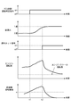
この協調制御作用を図3に示すタイムチャートにより説明すると、駆動輪スリップの発生によりTCS制御開始判定信号がoffからonになると(t1)、トラクション作動指令による燃料カットに先行して2速から1速へ変速するダウンシフト指令が出力され、しかも、ダウンシフトが1速への変速が完了する直前まで待たれ(t2)、この遅れ時間(t2−t1)を経過した時点で燃料カットによるトラクション制御が行われる。
【0075】
このように、TCS制御開始判定信号の出力から遅れ時間(t2−t1)だけトラクション制御の開始が待たれるため、図3のエンジン回転数特性に示すように、この遅れ時間(t2−t1)の間にエンジン回転数が上昇し、その後、燃料カットによりエンジン回転数が低下してもエンジンストール回転数以下まで低下することがなく、低エンジン回転での発進時や走行時であってもTCS作動によるエンジンストールを確実に回避することができる。
【0076】
さらに、エンジン回転数が十分に上昇すると、その時点t2で直ちにトラクション作動指令が出されて燃料カットが行われるため、図3の前後輪回転数差特性に示すように、TCS作動要求に応えて駆動輪スリップを設定しきい値α以下に抑えるスリップ抑制が達成される。
【0077】
ステップ32〜ステップ34においては、ダウンシフト指令を出力した時点での車速VSPとエンジン回転数NEにより、高車速ほど、また、高エンジン回転ほど長い遅れ時間に設定され、ダウンシフト指令から設定された遅れ時間を経過した後、TCSコントローラ1に対しトラクション作動指令が出力される。
【0078】
ここで、車速VSPとエンジン回転数NEにより遅れ時間を設定する理由は、ダウンシフト指令からダウンシフトが完了するまでの変速所要時間は、高車速ほど、また、高エンジン回転ほど長い時間となることによる。
【0079】
つまり、車速VSPとエンジン回転数NEにより変速所要時間を推定しながら遅れ時間を設定することになり、ダウンシフト指令を出力した時点からトラクション制御の作動を開始するまでの遅れ時間を、ダウンシフトが完了するまでの変速所要時間とほぼ一致する設定とすることもできるし、変速所要時間より少し短い時間の設定とすることもできる。この実施の形態1では、変速完了の直前で十分にエンジン回転数が上昇することから、変速所要時間より少し短い時間を遅れ時間として設定している。
【0080】
次に、効果を説明する。
【0081】
(1) TCS&AT協調コントローラ3において、1速以外の変速段で発進や走行をしている時、駆動輪スリップ時であると判定されると、先ず、ダウンシフト指令がATコントローラ2に出力され、ダウンシフトの進行によりエンジンストールが発生する可能性のないエンジン回転数域までエンジン回転数が上昇するまで待たれ、エンジン4の駆動力を低減する制御を開始するトラクション作動指令がTCSコントローラ1に出力されるため、駆動輪スリップが発生した時、低エンジン回転での発進時や走行時であってもTCS作動によるエンジンストールを確実に回避しながら、TCS作動要求に応えて駆動輪スリップの抑制を達成することができる。
【0082】
(2) TCS&AT協調コントローラ3において、ダウンシフト指令を出力した時点での車速VSPとエンジン回転数NEにより、高車速ほど、また、高エンジン回転ほど長い時間による遅れ時間タイマー値TMに設定され、ダウンシフト指令から設定された遅れ時間タイマー値TMによる時間を経過した後、TCSコントローラ1に対しトラクション作動指令が出力されるため、タイマー管理によりエンジンストールを確実に回避するトラクション制御の開始タイミングを得ることができる。
【0083】
(3) TCS&AT協調コントローラ3からATコントローラ2に出力されるダウンシフト指令が、強制的にダウンシフトさせる変速指令であるため、ダウンシフトしやすい変速パターンを選択する場合には、その時の運転点によってはダウンシフト指令から遅れて変速が開始されることがあるが、強制的なダウンシフト指令の場合、常にダウンシフト指令から遅れることなく変速が開始され、トラクション制御の開始時期を早めることができる。
【0084】
(実施の形態2)
実施の形態2は請求項3,請求項5,請求項6に記載の発明に対応するトラクション制御と自動変速制御との協調制御装置である。
【0085】
構成については、図1に示す実施の形態1の構成と同様であるので、図示並びに説明を省略する。
【0086】
次に、作用を説明する。
【0087】
[協調制御作動処理]
図4はTCSコントローラ1及びTCS&AT協調コントローラ3で行われるトラクションと自動変速の協調制御作動処理の流れを示すフローチャートで、以下、各ステップについて説明する。
【0088】
ステップ20〜ステップ23は、図2に示すステップ20〜ステップ23と同様であるので説明を省略する。
【0089】
ステップ40では、ステップ23での駆動スリップ条件が成立した時点でのエンジン回転数NEが、トラクション制御装置が作動してもエンジンストールが発生する可能性のある第1設定エンジン回転数NE1以下であるかどうかが判断され、YESの場合はステップ41へ進み、NOの場合はステップ45へ進む。
【0090】
ステップ41では、ATコントローラ2からの変速段信号及びモードスイッチ信号に基づいて、変速段が2速以上、または、スノーモード選択時(2速)かどうかが判断され、YESの場合にはステップ43へ進み、NOの場合にはステップ42へ進む。
【0091】
ステップ42では、エンジン回転数NEがNE≦NE1であり、且つ、変速段がダウンシフトの余地がない1速であり、トラクション作動を行えばエンジンストールの可能性が高いため、トラクション作動が禁止される。
【0092】
ステップ43では、ステップ41で変速段が2速以上であると判断されると、ATコントローラ2に対し強制的に変速段を1速下の変速段に下げるダウンシフト指令(2→1や3→2等)が出力され、また、ステップ41でスノーモード選択時あると判断されると、スノーモードからTCSモードの変速パターンに切り換えるダウンシフト指令が出力され、ステップ44へ進む。
【0093】
ここで、ATコントローラ2には、車速VSPと第1スロットル開度TVOをパラメータとして、図5に示すように、通常走行を基準として各変速段の領域が設定されたノーマルモードの変速パターンと、図6に示すように、ノーマルモードにおける1速の使用領域を全て2速の使用領域としているスノーモードの変速パターンと、第1スロットル開度TVOが低い領域はノーマルモード変速線より高速側で、第1スロットル開度TVOが高い領域はノーマルモード変速線より低速側に設定された変速線を有するTCSモードの変速パターンとが予め設定されていて、モード切換スイッチ13へのスイッチ操作によりノーマルモードとスノーモードの変速パターンを選択され、スノーモードの選択時に駆動輪スリップが発生すると、TCSモードに切り換えられる。
【0094】
ステップ44では、エンジン回転数NEが、トラクション制御装置が作動してもエンジンストールが発生することのない第2設定エンジン回転数NE2以上かどうかが判断され、NE≧NE1の条件が成立するまで一定周期毎に判断は繰り返され、NE≧NE1の条件が成立すると、ステップ45へ進む。
【0095】
ステップ45では、ステップ34でYESと判断されると、TCSコントローラ1に対しトラクション作動指令が出力される。
【0096】
このステップ40〜ステップ45が、TCS&AT協調コントローラ3で行われる協調制御である。
【0097】
[協調制御作用]
図4のステップ44において、ダウンシフト指令を出力した時点からのエンジン回転数NEが監視され、トラクション制御装置が作動してもエンジンストールが発生することのない第2設定エンジン回転数NE2に達するまで待たれ、第2設定エンジン回転数NE2に達したらステップ45へ進み、トラクション作動指令が出力される。
【0098】
すなわち、トラクション制御を待つのはエンジンストールの確実な回避を目指すためである。一方、トラクション作動要求が出ている以上、なるべく早くトラクション制御を開始したい。そこで、これら2つの要求をうまく両立させるため、エンジン回転数NEを監視してトラクション制御の開始時期を決めるようにしている。
【0099】
変速パターンとして、ダウンシフトしやすいTCSモードの変速パターンが設定され、TCS&AT協調コントローラ3からATコントローラ2に出力されるダウンシフト指令が、その時点で選択されているスノーモードの変速パターンに代えTCSモードの変速パターンを選択するパターン変更指令とされるため、パターン変更指令により、2速→1速のダウンシフトが行われる。
【0100】
ステップ23の駆動スリップ条件が成立した時点でのエンジン回転数NEが、トラクション制御装置が作動してもエンジンストールが発生する可能性のないエンジン回転数域(NE>NE1)である場合、ステップ40からステップ45へと進み、ダウンシフトによる協調制御を行うことなく、直ちにトラクション作動指令がTCSコントローラ1に出力される。
【0101】
次に、効果を説明する。
【0102】
(4) ステップ44において、ダウンシフト指令を出力した時点からのエンジン回転数NEが監視され、トラクション制御装置が作動してもエンジンストールが発生することのない第2設定エンジン回転数NE2に達するまで待たれ、第2設定エンジン回転数NE2に達したらトラクション作動指令が出力されるため、エンジンストールを確実に回避しながら、ダウンシフト指令から最短の遅れ時間が経過した時点を、トラクション制御の開始タイミングとすることができる。
【0103】
(5) 変速パターンとして、ダウンシフトしやすいTCSモードの変速パターンが設定され、TCS&AT協調コントローラ3からATコントローラ2に出力されるダウンシフト指令が、その時点で選択されているスノーモードの変速パターンに代えTCS変速パターンを選択するパターン変更指令とされるため、変速パターンの変更によりダウンシフトを実行させることができる。
【0104】
(6) ステップ23での駆動スリップ条件が成立した時点でのエンジン回転数NEが、トラクション制御装置が作動してもエンジンストールが発生する可能性のないエンジン回転数域(NE>NE1)である場合、ダウンシフトによる協調制御を行うことなく、直ちにトラクション作動指令がTCSコントローラ1に出力されるため、実際にエンジンストールが発生するような必要時にのみ、ダウンシフトによる協調制御が行われ、それ以外の時には、直ちにトラクション制御が開始されるため、無用なダウンシフトによる変速ショックを防止できるばかりでなく、エンジンストール回避制御が不必要な時に駆動スリップを応答良く抑制することができる。
【0105】
(その他の実施の形態)
実施の形態1,2では、TCS&AT協調コントローラ3をTCSコントローラ1とATコントローラ2に対し独立のコントローラとして設ける例を示したが、TCSコントローラ1内にTCS&AT協調制御部を追加しても良いし、また、ATコントローラ2内にTCS&AT協調制御部を追加しても良い。
【0106】
実施の形態1,2では、自動変速機として有段変速機を用いる例を示したが、ベルト式やトロイダル式等の無段変速機を用いても良い。
【0107】
実施の形態1では、車速とエンジン回転数によるタイマー管理にてTCS作動のタイミングをとる例を示し、実施の形態2では、エンジン回転数の監視によりTCS作動のタイミングをとる例を示したが、変速機の入出力回転数の比である変速比を測定し、変速の進行を測定変速比の変化により監視しながらTCS作動のタイミングをとるようにしても良いし、また、エンジン回転数に相当する値である変速機入力回転数を監視しながらTCS作動のタイミングをとる例としても良い。
【0108】
実施の形態1,2では、ダウンシフト指令によりダウンシフトさせる構成として、強制的に変速指令を出す例と、変速パターンを変更する例を示したが、変速パターンの変速線自体を変更する例としても良い。
【0109】
実施の形態1,2では、駆動輪スリップを検出するスリップ状態として、駆動輪と従動輪の速度差である前後輪回転速度差とする例を示したが、駆動輪スリップ率や駆動輪加速度等のように他のスリップ情報を用いて駆動輪スリップを検出する例としても良い。
【0110】
実施の形態2において、第1エンジン回転数設定値NE1と第2エンジン回転数設定値NE2は、固定値により与えても良いが、TCSのトルクダウン量はスリップ状態(例えば、駆動輪加速度)により異なるため、第1エンジン回転数設定値NE1と第2エンジン回転数設定値NE2もスリップ状態により変更する可変値により与えても良い。この可変値で与えた場合、スリップ状態(或いはトルクダウン量)にかかわらず、最適のエンジン回転数設定値NE1,NE2を得ることができる。
【図面の簡単な説明】
【図1】実施の形態1のトラクション制御と自動変速制御との協調制御装置が適用された車両を示す全体システム図である。
【図2】実施の形態1のTCSコントローラ1及びTCS&AT協調コントローラ3で行われるトラクション制御と自動変速制御の協調制御作動処理の流れを示すフローチャートである。
【図3】実施の形態1のトラクション制御と自動変速制御との協調制御作用を示すタイムチャートである。
【図4】実施の形態2のTCSコントローラ1及びTCS&AT協調コントローラ3で行われるトラクション制御と自動変速制御の協調制御作動処理の流れを示すフローチャートである。
【図5】実施の形態2のATコントローラ2に設定されているノーマルモードの変速パターンを示す図である。
【図6】実施の形態2のATコントローラ2に設定されているスノーモードの変速パターンを示す図である。
【図7】実施の形態2のATコントローラ2に設定されているTCSモードの変速パターンを示す図である。
【符号の説明】
1 TCSコントローラ(トラクション制御装置)
2 ATコントローラ(自動変速制御装置)
3 TCS&AT協調コントローラ(協調制御手段)
4 エンジン
5 ENGコントローラ
6 自動変速機
7 アクセルペダル
8 第1スロットル弁
9 スロットルアクチュエータ
10 第2スロットル弁
11 スロットル開度センサ
12FR,12FL,12RR,12RL 車輪速センサ
13 モード切換スイッチ
14 車速算出部
15 エンジン回転数センサ
FR 右前輪
FL 左前輪
RR 右後輪
RL 左後輪[0001]
BACKGROUND OF THE INVENTION
The present invention relates to traction control and automatic that are applied to a vehicle in which both a traction control device (abbreviated as TCS) for suppressing drive wheel slip and an automatic transmission control device that performs stepped or continuously variable transmission are mounted. It belongs to the technical field of cooperative control devices with shift control.
[0002]
[Prior art]
Conventionally, as a cooperative control device for traction control and automatic shift control, for example, a device described in JP-A-9-287489 is known.
[0003]
In this publication, the driving force control of a vehicle equipped with an automatic transmission is intended to suppress an increase in shift shock while being stably performed regardless of the throttle opening degree. Shift control is performed to switch from the normal mode shift schedule to the TCS mode shift schedule. The TCS mode shift schedule is faster than the normal mode in the low throttle opening range, and the engine speed is predetermined by downshift. A technique is described in which the shift line is set to be equal to or greater than the value and the shift line is set on the low speed side in the high throttle opening range compared to the normal mode.
[0004]
[Problems to be solved by the invention]
However, in the conventional cooperative control device of traction control and automatic shift control, the TCS command signal for suppressing the driving force and the shift command signal for selecting the TCS shift schedule are output at the same time. There is a problem that the shift is delayed with respect to the operation, and the engine stall cannot be surely avoided.
[0005]
That is, while the TCS side suppresses the driving force with good response first by fuel cut or the like, the shift control side has a delay of at least the shift required time from the command output until the actual downshift is completed. Due to this delay, even if two command signals are output at the same time, the TCS control operates with good response, so that the engine speed decreases significantly due to the TCS control before the engine speed increases due to the downshift. May lead to. In particular, when driving wheel slip occurs even when the engine speed is low, such as when traveling on a low μ road, the possibility of engine stall is increased.
[0006]
A specific example will be described. When starting a vehicle on a slippery road surface such as a snowy road or a muddy road, snow that prevents the drive wheels from slipping to reduce acceleration performance or to prevent the vehicle from moving forward. 2. Description of the Related Art As a shift control device for an automatic transmission having a mode, there is known a device for starting a second speed by prohibiting a shift to the first speed of the automatic transmission when a snow mode is selected by a driver's switch operation. (For example, see JP-A-3-362).
[0007]
When the snow mode is selected as described above, the vehicle can be started by the second speed start, which has a lower torque than the first speed start, so that it is possible to normally prevent the drive wheels from slipping. However, if the driver accidentally depresses the accelerator pedal by a large amount, the torque transmitted to the drive wheels will increase even if the vehicle starts at the second speed, and the drive wheels may slip. .
[0008]
In order to prevent such slipping, a method of combining with a traction control system (TCS) that reduces engine torque by fuel cut, throttle valve closing control, ignition timing retard control, or the like can be considered.
[0009]
However, with this combination, the engine speed when starting at the 2nd speed is lower than when starting at the 1st speed. In this state, when the TCS operates to perform fuel cut or the like and the engine torque is reduced, the engine speed is reduced. In the past, it has been difficult to combine a shift control device for an automatic transmission having a snow mode with a TCS because the possibility of engine stall occurring due to a significant decrease.
[0010]
In addition, when slip occurs in the driving wheel, when the driving force is reduced by operating the TCS, a technique for prohibiting the operation of the TCS or prohibiting an upshift is also known in order to avoid engine stall. It is.
[0011]
However, if the operation of the TCS is prohibited, the TCS operation request cannot be met, the significance of mounting the TCS is lost, and the occurrence of a large drive wheel slip is permitted. In addition, if the upshift is prohibited, it is possible to prevent a decrease in the engine speed due to the upshift, but an increase in the engine speed due to the downshift cannot be expected, and an engine stall may occur due to the operation of the TCS. Remain.
[0012]
The present invention has been made by paying attention to the above-mentioned problems. The object of the present invention is to ensure engine stall due to TCS operation even when driving wheel slip occurs, even when starting at low engine speed or during running. It is another object of the present invention to provide a cooperative control device for traction control and automatic transmission control that achieves suppression of drive wheel slip in response to a TCS operation request.
[0013]
[Means for Solving the Problems]
According to the first aspect of the present invention, the drive wheel slip determination means for determining that the slip equivalent value of the drive wheel connected to the engine via the automatic transmission is greater than or equal to the set threshold value, and the drive wheel slip A traction control device comprising driving force suppression means for starting control to reduce the driving force of the engine based on a traction operation command at the time of determination;
In a vehicle equipped with an automatic transmission control device that controls the transmission ratio of the automatic transmission based on a transmission command,
When starting or running at a speed other than the maximum gear ratio, when the driving wheel slip determining means determines that the driving wheel slips, it first outputs a downshift command to the automatic transmission control device, Waiting for the engine speed to increase due to the progress of the downshift, if the engine speed increases to the engine speed range where there is no possibility of engine stall, Traction operation command to start control to reduce engine driving force Before Coordinate control means for outputting to the driving force suppression means is provided.
[0014]
In the invention according to
Based on at least one of the vehicle speed and the engine speed at the time when the downshift command is output, the cooperative control means is set to a longer delay time for a higher vehicle speed and a higher engine speed, and the delay set from the downshift command is set. A feature is that the traction operation command is output to the driving force suppressing means after a lapse of time.
[0015]
In the invention according to
The cooperative control means monitors the engine speed from the time when the downshift command is output, and waits until a second set engine speed is reached at which no engine stall occurs even if the traction control device is activated. It is characterized in that it is a means for outputting a traction operation command when the set engine speed reaches two.
[0016]
Among the present inventions, the invention according to
The downshift command output from the cooperative control means to the automatic shift control device is a shift command for forcibly downshifting.
[0017]
In the invention according to
As a shift pattern, set a TCS shift pattern that is easy to downshift compared to at least other shift patterns,
The downshift command output from the cooperative control means to the automatic shift control device is a pattern change command for selecting a TCS shift pattern instead of the shift pattern selected at that time.
[0018]
In the invention according to claim 6 among the present inventions, claims 1 to In any one of 5 In the cooperative control device of the described traction control and automatic shift control,
If the engine speed at the time when the drive slip condition is satisfied is in an engine speed range where there is no possibility of engine stall even if the traction control device operates, immediately without performing coordinated control by downshifting It is a means for outputting a traction operation command to the driving force suppressing means.
[0019]
Operation and effect of the invention
The operation and effect of the invention of
[0020]
The basic action of the traction control device is that the driving wheel slip determination means has a slip equivalent value of the driving wheel connected to the engine via the automatic transmission at or above the set threshold value when starting or running when driving wheel slip occurs. If it is determined, the driving force suppression means starts control for reducing the driving force of the engine based on the traction operation command.
[0021]
The basic operation of the automatic transmission control device is that a shift command (for obtaining a target gear ratio suitable for the driving state and driving state of the vehicle when the driving state (for example, vehicle speed) and driving state (for example, throttle opening) of the vehicle changes). The gear ratio of the automatic transmission is controlled based on an upshift command or a downshift command.
[0022]
When starting or running at a speed other than the maximum gear ratio, when the driving wheel slip determination means determines that the driving wheel slips, the cooperative control means first sends a downshift command to the automatic transmission control device. The traction operation command that starts the control to reduce the driving force of the engine is waited until the engine speed rises to the engine speed range where there is no possibility of engine stall due to the progress of downshift, and the driving force is suppressed Output to the means.
[0023]
That is, in the cooperative control, the flow of driving wheel slip determination → downshift command → waiting for engine speed increase → traction operation command, when the drive wheel slip occurs, a downshift command is output prior to the traction operation command, In addition, since an increase in the engine speed is awaited due to the downshift, it is possible to reliably avoid engine stall due to the TCS operation even when starting at low engine speed or during traveling. Further, since the traction operation command is issued immediately when the engine speed increases, suppression of drive wheel slip is achieved in response to the TCS operation request.
[0024]
Therefore, when driving wheel slip occurs, even when starting at low engine speed or during running, engine stall due to TCS operation is reliably avoided, and driving wheel slip suppression is achieved in response to TCS operation requests. be able to.
[0025]
The operation and effect of the invention of
[0026]
In the coordinated control means, the delay time set from the downshift command is set to a longer delay time as the vehicle speed is higher or the engine speed is higher, depending on at least one of the vehicle speed and the engine speed when the downshift command is output. After elapses, a traction operation command is output to the driving force suppressing means.
[0027]
That is, the time required for shifting from the downshift command to the completion of the downshift is longer as the vehicle speed is higher and as the engine speed is higher.
[0028]
Therefore, the delay time from when the downshift command is output to when the traction control operation is started can be set to substantially match the shift required time until the downshift is completed, or slightly less than the shift required time. A short time can be set. That is, it is possible to obtain the start timing of traction control that reliably avoids engine stall by timer management.
[0029]
The operation and effect of the invention of
[0030]
The cooperative control means monitors the engine speed from the time when the downshift command is output, and waits until the second set engine speed at which no engine stall occurs even if the traction control device operates is reached. When the set engine speed is reached, a traction operation command is output.
[0031]
That is, the reason for waiting for traction control is to aim at reliable avoidance of engine stall. On the other hand, I want to start traction control as soon as possible as long as a traction operation request is issued. Therefore, in order to balance these two requirements well, the engine speed is monitored to determine the start time of traction control.
[0032]
Therefore, by monitoring the engine speed, the point in time when the shortest delay time has elapsed from the downshift command can be set as the start timing of the traction control while reliably avoiding the engine stall.
[0033]
The operation and effect of the invention of
[0034]
The downshift command output from the cooperative control means to the automatic shift control device is a shift command for forcibly downshifting.
[0035]
Therefore, when selecting a shift pattern that is easy to downshift, depending on the operating point at that time, the shift may start after the downshift command, but in the case of a forced downshift command, the downshift command is always used. Thus, the shift is started without delay, and the start time of the traction control can be advanced.
[0036]
The operation and effect of the invention of
[0037]
As a shift pattern, a TCS shift pattern that is easy to downshift compared to at least other shift patterns is set, and the downshift command output from the cooperative control means to the automatic shift control device is changed to the currently selected shift pattern. Instead, it is a pattern change command for selecting a TCS shift pattern.
[0038]
Therefore, when the snow mode shift pattern with the fixed 2nd speed is set, if the TCS shift pattern is selected based on the occurrence of the drive wheel slip, the shift pattern is changed so that the downshift from the 2nd speed to the 1st speed is performed. The downshift can be executed by the change.
[0039]
The operation and effect of the invention of claim 6 will be described.
[0040]
If the engine speed at the time when the drive slip condition is satisfied is in an engine speed range where there is no possibility of engine stall even if the traction control device operates, immediately without performing coordinated control by downshifting A traction operation command is output to the traction control device.
[0041]
Therefore, coordinated control by downshift is performed only when it is necessary that an engine stall actually occurs, and at other times, traction control is started immediately, so it is possible to prevent a shift shock due to unnecessary downshift. Therefore, when the engine stall avoidance control is unnecessary, the drive slip can be suppressed with good response.
[0042]
DETAILED DESCRIPTION OF THE INVENTION
Hereinafter, embodiments of the present invention will be described with reference to the drawings.
[0043]
(Embodiment 1)
First, the configuration will be described.
[0044]
The first embodiment is a cooperative control device for traction control and automatic transmission control corresponding to the inventions of
[0045]
The TCS controller 1 (traction control device) is constituted by a microcomputer or the like, and the right front wheel speed VWFR, the left front wheel speed VWFL, the right rear wheel speed VWRR, and the left rear wheel speed from the wheel speed sensors 12FR, 12FL, 12RR, and 12RL, respectively. VWRL and the first throttle opening TVO from the
[0046]
When the
[0047]
The
[0048]
The wheel speed sensors 12FR, 12FL, 12RR, and 12RL are sensors that detect the respective wheel speeds of the right front wheel FR and the left front wheel FL, which are driven wheels, and the right rear wheel RR and the left rear wheel RL, which are drive wheels. The wheel speed information based on the right front wheel speed VWFR, the left front wheel speed VWFL, the right rear wheel speed VWRR, and the left rear wheel speed VWRL is information for determining drive wheel slip in the
[0049]
The AT controller 2 (automatic shift control device) is constituted by a microcomputer or the like, and includes a first throttle opening TVO from the
[0050]
The vehicle
[0051]
The mode change-over switch 13 includes a normal mode shift pattern (see FIG. 5) and a snow mode shift pattern (see FIG. 5) in which regions of the respective shift stages are set by the
[0052]
The TCS & AT cooperative controller 3 (cooperative control means) is constituted by a microcomputer or the like, and determines the engine speed NE from the
[0053]
Next, the operation will be described.
[0054]
[Cooperative control operation processing]
FIG. 2 is a flowchart showing a flow of cooperative control operation processing of traction and automatic shift performed by the
[0055]
In
[0056]
In
[0057]
In
[0058]
In
[0059]
The processing of
[0060]
In
[0061]
In
[0062]
In
[0063]
In
[0064]
In
[0065]
In
[0066]
[0067]
[Cooperative control action]
First, when the traction control device and the automatic transmission control device are devices that are controlled independently of each other, the basic operation of the traction control device is as follows: If it is determined that the slip equivalent value (VWR-VWF) of the left and right rear wheels RR, RL connected to the
[0068]
On the other hand, the basic operation of the automatic shift control device is to search whether the operating point by the vehicle speed VSP and the first throttle opening TVO crosses the shift line on the shift pattern when the vehicle speed VSP and the first throttle opening TVO change. When the shift line is crossed, the shift stage of the automatic transmission 6 is controlled based on an upshift command or a downshift command for switching from the shift stage before crossing to the shift stage after crossing.
[0069]
Next, in the case of the apparatus according to the first embodiment in which cooperative control of traction and automatic transmission is performed, the cooperative control action described below is performed.
[0070]
First, even if it is determined in
[0071]
Then, when it is determined in
[0072]
In this coordinated control, first, in
[0073]
That is, in the cooperative control, the flow is as follows: drive wheel slip determination (step 23) → downshift command (step 31) → wait for engine speed increase (steps 32-34) → traction operation command (step 35).
[0074]
This cooperative control action will be described with reference to the time chart shown in FIG. 3. When the TCS control start determination signal turns from off to on due to the occurrence of drive wheel slip (t1), the 2nd speed starts from the 2nd speed prior to the fuel cut by the traction operation command. A downshift command for shifting to a high speed is output, and a traction control by fuel cut is performed when this delay time (t2−t1) has elapsed (t2) until the downshift is completed just before the shift to the first speed is completed. Is done.
[0075]
Thus, since the start of the traction control is waited for the delay time (t2-t1) from the output of the TCS control start determination signal, the delay time (t2-t1) of this delay time (t2-t1) is shown in FIG. In the meantime, the engine speed increases, and even if the engine speed decreases due to fuel cut, it does not decrease below the engine stall speed, and TCS is activated even when starting or running at low engine speed. The engine stall due to can be surely avoided.
[0076]
Further, when the engine speed increases sufficiently, a traction operation command is immediately issued at the time t2, and fuel cut is performed. Therefore, as shown in the front-rear wheel speed difference characteristic of FIG. Slip suppression is achieved that suppresses drive wheel slip to a set threshold value α or less.
[0077]
In
[0078]
Here, the reason for setting the delay time based on the vehicle speed VSP and the engine speed NE is that the shift required time from the downshift command to the completion of the downshift is longer as the vehicle speed is higher and the engine speed is higher. by.
[0079]
In other words, the delay time is set while estimating the shift required time based on the vehicle speed VSP and the engine speed NE, and the delay time from when the downshift command is output to when the traction control operation starts is reduced by the downshift. It can be set to substantially coincide with the required shift time until completion, or can be set to a time slightly shorter than the required shift time. In the first embodiment, since the engine speed sufficiently increases immediately before the completion of the shift, a time slightly shorter than the required shift time is set as the delay time.
[0080]
Next, the effect will be described.
[0081]
(1) When the TCS &
[0082]
(2) In the TCS &
[0083]
(3) Since the downshift command output from the TCS & AT
[0084]
(Embodiment 2)
The second embodiment is a cooperative control device for traction control and automatic transmission control corresponding to the inventions of
[0085]
Since the configuration is the same as the configuration of the first embodiment shown in FIG. 1, the illustration and description are omitted.
[0086]
Next, the operation will be described.
[0087]
[Cooperative control operation processing]
FIG. 4 is a flowchart showing a flow of cooperative control operation processing of traction and automatic shift performed by the
[0088]
[0089]
In
[0090]
In
[0091]
In
[0092]
In
[0093]
Here, the
[0094]
In
[0095]
In
[0096]
[0097]
[Cooperative control action]
In
[0098]
That is, the reason for waiting for traction control is to aim at reliable avoidance of engine stall. On the other hand, I want to start traction control as soon as possible as long as a traction operation request is issued. Therefore, in order to make these two requirements compatible, the engine speed NE is monitored to determine the start time of the traction control.
[0099]
As a shift pattern, a TCS mode shift pattern that is easy to downshift is set, and the TCS & AT
[0100]
When the engine speed NE at the time when the drive slip condition of
[0101]
Next, the effect will be described.
[0102]
(4) In
[0103]
(5) A TCS mode shift pattern that is easy to downshift is set as the shift pattern, and the downshift command output from the TCS & AT
[0104]
(6) The engine speed NE at the time when the drive slip condition in
[0105]
(Other embodiments)
In the first and second embodiments, the example in which the TCS & AT
[0106]
In the first and second embodiments, an example in which a stepped transmission is used as an automatic transmission is shown, but a continuously variable transmission such as a belt type or a toroidal type may be used.
[0107]
In the first embodiment, an example of taking the timing of the TCS operation by the timer management based on the vehicle speed and the engine speed is shown. In the second embodiment, an example of taking the timing of the TCS operation by monitoring the engine speed is shown. It is also possible to measure the speed ratio, which is the ratio of the input / output speed of the transmission, and to take the timing of TCS operation while monitoring the progress of the speed change by measuring the change in the speed ratio, or equivalent to the engine speed. It is also possible to take an example in which the timing of the TCS operation is taken while monitoring the transmission input rotational speed that is a value to be transmitted.
[0108]
In the first and second embodiments, the example in which the shift command is forcibly issued and the example in which the shift pattern is changed are shown as the configuration for downshifting by the downshift command. However, as an example in which the shift line of the shift pattern itself is changed. Also good.
[0109]
In the first and second embodiments, as an example of the slip state for detecting the drive wheel slip, the difference between the front and rear wheel rotational speeds, which is the speed difference between the drive wheel and the driven wheel, is shown. It is good also as an example which detects driving wheel slip using other slip information like this.
[0110]
In the second embodiment, the first engine speed setting value NE1 and the second engine speed setting value NE2 may be given as fixed values, but the TCS torque reduction amount depends on the slip state (for example, driving wheel acceleration). Since they are different, the first engine speed setting value NE1 and the second engine speed setting value NE2 may also be given by variable values that change depending on the slip state. When this variable value is given, optimum engine speed setting values NE1 and NE2 can be obtained regardless of the slip state (or torque down amount).
[Brief description of the drawings]
FIG. 1 is an overall system diagram showing a vehicle to which a cooperative control device for traction control and automatic transmission control according to a first embodiment is applied.
FIG. 2 is a flowchart showing a flow of cooperative control operation processing of traction control and automatic shift control performed by the
FIG. 3 is a time chart showing a cooperative control action between the traction control and the automatic transmission control according to the first embodiment.
FIG. 4 is a flowchart showing a flow of cooperative control operation processing of traction control and automatic shift control performed by the
FIG. 5 is a diagram showing a shift pattern in a normal mode set in the
FIG. 6 is a diagram showing a shift pattern in a snow mode set in the
FIG. 7 is a diagram showing a shift pattern in a TCS mode set in the
[Explanation of symbols]
1 TCS controller (traction control device)
2 AT controller (automatic shift control device)
3 TCS & AT cooperative controller (cooperative control means)
4 engine
5 ENG controller
6 Automatic transmission
7 Accelerator pedal
8 First throttle valve
9 Throttle actuator
10 Second throttle valve
11 Throttle opening sensor
12FR, 12FL, 12RR, 12RL Wheel speed sensor
13 Mode selector switch
14 Vehicle speed calculator
15 Engine speed sensor
FR front right wheel
FL Front left wheel
RR Right rear wheel
RL left rear wheel
Claims (6)
変速指令に基づいて前記自動変速機の変速比を制御する自動変速制御装置と、が共に搭載された車両において、
最大変速比以外で発進や走行をしている時、前記駆動輪スリップ判定手段により駆動輪スリップ時であると判定されると、先ず、ダウンシフト指令を自動変速制御装置に出力し、ダウンシフトの進行によるエンジン回転数の上昇を待ち、エンジンストールが発生する可能性のないエンジン回転数域までエンジン回転数が上昇すると、エンジンの駆動力を低減する制御を開始するトラクション作動指令を前記駆動力抑制手段に出力する協調制御手段を設けたことを特徴とするトラクション制御と自動変速制御との協調制御装置。Drive wheel slip determination means for determining that the slip equivalent value of the drive wheel connected to the engine via the automatic transmission is greater than or equal to a set threshold value, and driving the engine based on a traction operation command when determining the drive wheel slip A traction control device comprising driving force suppression means for starting control to reduce force;
In a vehicle equipped with an automatic transmission control device that controls the transmission ratio of the automatic transmission based on a transmission command,
When starting or running at a speed other than the maximum gear ratio, if the driving wheel slip determining means determines that the driving wheel is slipping, first, a downshift command is output to the automatic transmission control device, and the downshift wait for increase in the engine speed due to progress, the engine speed until the engine rotational speed range no possibility that the engine stall will occur rises, before Symbol driving force traction operation command to start the control for reducing the driving force of the engine A cooperative control device for traction control and automatic shift control, characterized in that a cooperative control means for outputting to the suppression means is provided.
前記協調制御手段を、ダウンシフト指令を出力した時点での車速とエンジン回転数の少なくとも一方により、高車速ほど、また、高エンジン回転ほど長い遅れ時間に設定し、ダウンシフト指令から設定された遅れ時間を経過した後、駆動力抑制手段に対しトラクション作動指令を出力する手段としたことを特徴とするトラクション制御と自動変速制御との協調制御装置。In the cooperative control device of traction control and automatic transmission control according to claim 1,
Based on at least one of the vehicle speed and the engine speed at the time when the downshift command is output, the cooperative control means is set to a longer delay time for a higher vehicle speed and a higher engine speed, and the delay set from the downshift command is set. A cooperative control device for traction control and automatic transmission control, characterized in that after a lapse of time, the traction operation command is output to the driving force suppression means.
前記協調制御手段を、ダウンシフト指令を出力した時点からのエンジン回転数を監視し、トラクション制御装置が作動してもエンジンストールが発生することのない第2設定エンジン回転数に達するまで待ち、第2設定エンジン回転数に達したらトラクション作動指令を出力する手段としたことを特徴とするトラクション制御と自動変速制御との協調制御装置。In the cooperative control device of traction control and automatic transmission control according to claim 1,
The cooperative control means monitors the engine speed from the time when the downshift command is output, and waits until a second set engine speed is reached at which no engine stall occurs even if the traction control device is activated. 2. A cooperative control device for traction control and automatic transmission control, characterized in that the traction operation command is output when the set engine speed is reached.
前記協調制御手段から自動変速制御装置に出力されるダウンシフト指令を、強制的にダウンシフトさせる変速指令としたことを特徴とするトラクション制御と自動変速制御との協調制御装置。In the cooperative control device of traction control and automatic shift control according to any one of claims 1 to 3 ,
A cooperative control device for traction control and automatic transmission control, wherein the downshift command output from the cooperative control means to the automatic transmission control device is a transmission command for forcibly downshifting.
変速パターンとして、少なくとも他の変速パターンと比べてダウンシフトしやすいTCS変速パターンを設定し、
前記協調制御手段から自動変速制御装置に出力されるダウンシフト指令を、その時点で選択されている変速パターンに代えTCS変速パターンを選択するパターン変更指令としたことを特徴とするトラクション制御と自動変速制御との協調制御装置。In the cooperative control device of traction control and automatic shift control according to any one of claims 1 to 3 ,
As a shift pattern, set a TCS shift pattern that is easy to downshift compared to at least other shift patterns,
Traction control and automatic shift characterized in that the downshift command output from the cooperative control means to the automatic shift control device is a pattern change command for selecting a TCS shift pattern instead of the shift pattern currently selected. Coordinated control device with control.
駆動スリップ条件が成立した時点でのエンジン回転数が、トラクション制御装置が作動してもエンジンストールが発生する可能性のないエンジン回転数域である場合、ダウンシフトによる協調制御を行うことなく、直ちにトラクション作動指令を駆動力抑制手段に出力する手段としたことを特徴とするトラクション制御と自動変速制御との協調制御装置。In the cooperative control device of traction control and automatic shift control according to any one of claims 1 to 5 ,
If the engine speed at the time when the drive slip condition is satisfied is in an engine speed range where there is no possibility of engine stall even if the traction control device operates, immediately without performing coordinated control by downshifting A cooperative control device for traction control and automatic shift control, characterized in that the traction operation command is output to the driving force suppression means.
Priority Applications (1)
| Application Number | Priority Date | Filing Date | Title |
|---|---|---|---|
| JP30377499A JP3661759B2 (en) | 1999-10-26 | 1999-10-26 | Coordinated control device for traction control and automatic transmission control |
Applications Claiming Priority (1)
| Application Number | Priority Date | Filing Date | Title |
|---|---|---|---|
| JP30377499A JP3661759B2 (en) | 1999-10-26 | 1999-10-26 | Coordinated control device for traction control and automatic transmission control |
Publications (2)
| Publication Number | Publication Date |
|---|---|
| JP2001121992A JP2001121992A (en) | 2001-05-08 |
| JP3661759B2 true JP3661759B2 (en) | 2005-06-22 |
Family
ID=17925135
Family Applications (1)
| Application Number | Title | Priority Date | Filing Date |
|---|---|---|---|
| JP30377499A Expired - Fee Related JP3661759B2 (en) | 1999-10-26 | 1999-10-26 | Coordinated control device for traction control and automatic transmission control |
Country Status (1)
| Country | Link |
|---|---|
| JP (1) | JP3661759B2 (en) |
Cited By (1)
| Publication number | Priority date | Publication date | Assignee | Title |
|---|---|---|---|---|
| KR101664705B1 (en) * | 2015-06-16 | 2016-10-10 | 현대자동차주식회사 | Control method for vehicle |
Families Citing this family (5)
| Publication number | Priority date | Publication date | Assignee | Title |
|---|---|---|---|---|
| JP5315900B2 (en) * | 2008-09-30 | 2013-10-16 | マツダ株式会社 | Electric vehicle motor control method and electric vehicle drive device |
| JP5444691B2 (en) * | 2008-11-04 | 2014-03-19 | トヨタ自動車株式会社 | Control device for automatic transmission |
| JP5568527B2 (en) * | 2011-08-02 | 2014-08-06 | 株式会社デンソー | Vehicle control device |
| WO2015076134A1 (en) * | 2013-11-20 | 2015-05-28 | 本田技研工業株式会社 | Power transmission device |
| KR102323962B1 (en) * | 2020-09-10 | 2021-11-10 | 주식회사 현대케피코 | Shift control method and system under rapid acceleration of vehicle in low friction roads |
-
1999
- 1999-10-26 JP JP30377499A patent/JP3661759B2/en not_active Expired - Fee Related
Cited By (1)
| Publication number | Priority date | Publication date | Assignee | Title |
|---|---|---|---|---|
| KR101664705B1 (en) * | 2015-06-16 | 2016-10-10 | 현대자동차주식회사 | Control method for vehicle |
Also Published As
| Publication number | Publication date |
|---|---|
| JP2001121992A (en) | 2001-05-08 |
Similar Documents
| Publication | Publication Date | Title |
|---|---|---|
| US5813936A (en) | Driving force controller in vehicle for forcibly upshifting in response to a driving force traction controller and a vehicle stopped detection means | |
| JP2000230443A (en) | Automatic engine stopping device | |
| KR100222151B1 (en) | Driving force controller for a vehicle | |
| JP3189355B2 (en) | Acceleration slip control device for vehicles with automatic transmission | |
| JP3661759B2 (en) | Coordinated control device for traction control and automatic transmission control | |
| US5806010A (en) | Kinetic characteristic control system for vehicle | |
| JP3608481B2 (en) | Vehicle constant speed traveling device and vehicle speed control method | |
| JPH0231779B2 (en) | ||
| JPH094485A (en) | Driving force control device for vehicle | |
| JP4051932B2 (en) | Driving force control device | |
| JP3564862B2 (en) | Driving force control device for vehicles | |
| JP3985450B2 (en) | Driving force control device | |
| JP3674935B2 (en) | Anti-slip device for vehicle | |
| JP3575223B2 (en) | Driving force control device for vehicles | |
| JP2527034B2 (en) | Gear ratio control device for continuously variable transmission for vehicle | |
| JP3550956B2 (en) | Driving force control device for vehicles | |
| JP3726182B2 (en) | Accelerated slip control device | |
| JP3622257B2 (en) | Vehicle driving force control device | |
| JPH02195070A (en) | Vehicle controller | |
| JPH03103660A (en) | Change gear ratio control device for continuously variable transmission for vehicle | |
| JP2008019808A (en) | Traveling control device | |
| JPH06185608A (en) | Controller of vehicular automatic transmission | |
| JP2560487B2 (en) | Speed ratio control device for continuously variable transmission for vehicles | |
| JP3773788B2 (en) | Vehicle drive wheel slip control device | |
| JP2658559B2 (en) | Vehicle slip control device |
Legal Events
| Date | Code | Title | Description |
|---|---|---|---|
| RD04 | Notification of resignation of power of attorney |
Free format text: JAPANESE INTERMEDIATE CODE: A7424 Effective date: 20041111 |
|
| A977 | Report on retrieval |
Free format text: JAPANESE INTERMEDIATE CODE: A971007 Effective date: 20041126 |
|
| A131 | Notification of reasons for refusal |
Free format text: JAPANESE INTERMEDIATE CODE: A131 Effective date: 20041207 |
|
| A521 | Written amendment |
Free format text: JAPANESE INTERMEDIATE CODE: A523 Effective date: 20050126 |
|
| TRDD | Decision of grant or rejection written | ||
| A01 | Written decision to grant a patent or to grant a registration (utility model) |
Free format text: JAPANESE INTERMEDIATE CODE: A01 Effective date: 20050302 |
|
| A61 | First payment of annual fees (during grant procedure) |
Free format text: JAPANESE INTERMEDIATE CODE: A61 Effective date: 20050315 |
|
| R150 | Certificate of patent (=grant) or registration of utility model |
Free format text: JAPANESE INTERMEDIATE CODE: R150 |
|
| FPAY | Renewal fee payment (prs date is renewal date of database) |
Free format text: PAYMENT UNTIL: 20090401 Year of fee payment: 4 |
|
| LAPS | Cancellation because of no payment of annual fees |