JP3661118B2 - electromagnet - Google Patents
electromagnet Download PDFInfo
- Publication number
- JP3661118B2 JP3661118B2 JP16297497A JP16297497A JP3661118B2 JP 3661118 B2 JP3661118 B2 JP 3661118B2 JP 16297497 A JP16297497 A JP 16297497A JP 16297497 A JP16297497 A JP 16297497A JP 3661118 B2 JP3661118 B2 JP 3661118B2
- Authority
- JP
- Japan
- Prior art keywords
- iron core
- pipe
- stopper
- movable iron
- coil
- Prior art date
- Legal status (The legal status is an assumption and is not a legal conclusion. Google has not performed a legal analysis and makes no representation as to the accuracy of the status listed.)
- Expired - Lifetime
Links
Images


Description
【0001】
【発明の属する技術分野】
この発明は、コイルアッシーと、コイルアッシー内に収納されるチューブアッシーと、を有し、チューブアッシー内に配設される可動鉄心が、コイルアッシー内に配設されるコイルの励磁により固定鉄心側に摺動するように構成される電磁石に関する。
【0002】
【従来の技術】
従来、電磁石は、中空状に形成されるボビンと、ボビンに巻回される磁気コイルと、ボビン内に配置される固定鉄心と、固定鉄心に対して接近離隔するように摺動される可動鉄心と、を備えている。そして、一般的には、可動鉄心は磁気コイルの励磁により固定鉄心に吸着されるように作動されている。
【0003】
図4に示す電磁石20は、特に油浸型として油圧電磁弁等に広く使用されている。この電磁石20は、コイルアッシー21と、コイルアッシー21内に嵌合されるチューブアッシー26と、コイルアッシー21とチューブアッシー26とを固定するナット31と、を有して構成され、コイルアッシー21は中空丸状の磁性体の外ケース22内に磁気コイル23が巻回された中空状のボビン24とヨーク25が樹脂により一体的に成型され、チューブアッシー26は、固定鉄心27と可動鉄心28とを有し、さらに固定鉄心27と可動鉄心28を嵌合するパイプ29と、を有して構成されている。パイプ29は、リング状の非磁性体で形成されボビン24の中空部内周面に挿入されるとともに、一端は固定鉄心27に係合し溶着され、内周面に固定鉄心27に対して接近離隔する可動鉄心28が摺動可能に配置されている。また、パイプ29の他端はストッパ30が溶着され、コイルアッシー21とチューブアッシー26を一体的に固定するために、ナット31がストッパ30に螺合されて取り付けられていた。
【0004】
固定鉄心27には中心軸線に沿って図示しないピンが挿通される貫通孔27aが油通路を含めて形成されるとともに、先端部外周に雄ねじ27bが形成され雄ねじ27bによって図示しない弁体に取り付けられる。可動鉄心28には外周面の片面あるいは両面に、油が循環されるための油溝28aが軸方向に形成され、固定鉄心27側から流入された油が可動鉄心28を通りストッパ30側まで循環されていた。そして、必要な箇所には油の洩れ防止のためのシールが配設されていた。
【0005】
【発明が解決しようとする課題】
しかし、価格競争が激しくなってくると、従来の電磁石においても価格的な見直しを図らなければならない。特に油浸型の電磁石20にあっては内部に油が循環するため非磁性体のパイプ29が配置されている。パイプ29は一端が固定鉄心27に係合され他端が外ケース22より後方に突出するように配置されているので、パイプ29の中空部を塞ぐためのストッパ30が必要になっていた。しかし、ストッパ30は一端がパイプ29に溶接され他端がナット31に螺合するねじ部が形成されているため、ストッパ30自体が複雑で機械加工を要し製造コストがかかっていた。価格見直しに当たっては、個々の部品を廉価に製造することがコスト低減に繋がるため、パイプ29、特にパイプ29に溶着されるストッパ30を改良することが着目されていた。
【0006】
この発明は、上述の課題を解決するものであり、特に、パイプのストッパを形状変更することによって、ストッパを廉価に製造するとともに従来のナットを削除し、そのためにコスト低減を図ることのできる電磁石を提供することを目的とする。
【0007】
【課題を解決するための手段】
この発明にかかわる電磁石では、上記の課題を解決するために以下のように構成するものである。即ち、
一端が開口される外ケースとコイルが巻回される中空状のボビンとを有するコイルアッシーと、前記コイルアッシーに収納されパイプ及び固定鉄心・可動鉄心を有するチューブアッシーと、を備え、前記可動鉄心が前記コイルの励磁によって作動されるように構成される電磁石であって、
前記パイプが中空状に形成され、前記固定鉄心と前記可動鉄心とを収納する円筒部本体と、前記パイプ内の一方を塞ぐように配設されるストッパ部と、を有して形成され、
前記ストッパ部が、ストッパ部本体部を有する段付円板状に形成され、中央部において前記可動鉄心との接触面積を少なくするために前記ストッパ部本体部から前記パイプ内に向かって突起する突起部と、外周部において前記ストッパ部本体部から前記パイプ外に向かって突起する顎部と、を有して形成され、前記顎部が前記パイプの端面に係合するとともに、前記顎部の外周面が前記パイプの円筒部本体の外周面と略同径に形成されることを特徴とするものである。
【0008】
【発明の実施の形態】
以下、この発明の一実施の形態を図面に基づいて説明する。
【0009】
本形態の電磁石1は、図1に示すように、コイルアッシー2と、コイルアッシー2内に挿入されるチューブアッシー7と、を有して構成されている。コイルアッシー2は丸状の外ケース3と、外ケース3内に配置されるボビン5と、ボビン5を巻回するように配置されるコイル6と、を有し、チューブアッシー7は一方が開口され他方が閉口される筒状のパイプ8と、パイプ8内に配置される固定鉄心9・可動鉄心11と、を有して構成されている。
【0010】
外ケース3は磁性体で形成され、前端部(図1中、下方)がフランジ部3aを有して開口され、後部(図1中、上部)が本体部3bに対して小径に形成されるとともに後壁3cを有して閉口され全体に円筒状に形成されている。
【0011】
ボビン5は、樹脂等の非磁性体で中空状に形成され、外ケース3内に配置されている。また、ボビン5の外周面にコイル6を収納するための一対の壁部5aを有し、内周面にパイプ8を嵌着している。ボビン5と外ケース本体部3bの後端部との間には、パイプ8の外周面に沿ってヨーク13が配置され、ヨーク13・外ケース3・固定鉄心9・可動鉄心11との間で磁界を発生できるように構成している。
【0012】
パイプ8は、図2に示すように、非磁性体で円筒状に形成される円筒部本体81と後端部に溶接して配置されるストッパ部82からなり、パイプ8の前端部に固定鉄心9が係合される。
【0013】
ストッパ部82は、図2に示すように、3段の段付き円板状に形成され、本体部82aに対して中央部にパイプ8内に向かって突起する突起部82bが形成され、外周部が外側に突出する顎部82cが形成されている。顎部82cは円筒部本体81の端面81aに対して係合可能な係止部82dを有し、顎部82cの外径は、円筒部本体81の外径と略同様の寸法に形成されている。ストッパ部82の突起部82bは、可動鉄心11がストッパ部82に接触したときに油で密着することがないように可動鉄心11の接触面積を少なくするために形成されている。そしてストッパ部82はプレス加工され、円筒部本体81の端面81aに係止部82dを係合させた後円筒部本体81と溶接して一体化される。
【0014】
そして、ストッパ部82の本体部82aと外ケース3の後壁3cとの間に、波状の座板15が配置され、ボビン5の前端部に挿入された固定鉄心9に対して、パイプ8を付勢することにより、パイプ8を固定鉄心9に固着するとともに固定鉄心9を図示しない弁体側に押圧している。座板15はパイプ8のストッパ部82の形状に合わせて円板状に形成されてもよく、また長尺状に形成されるものであってもよい。いずれにしても座板15の波部が弾性状に形成されてパイプ8を固定鉄心9側に押圧するものであればよい。しかもこの座板15は波部の厚みの分のスペースを、パイプ8と外ケース8の後壁3cとの間に設けるだけなので、電磁石1をコンパクトにすることができる。
【0015】
固定鉄心9は外周面が2段に形成され、大径部9aが前述のようにボビン5の前端部に挿入され、小径部9bがパイプ8に嵌着されている。そして小径部9bの外周面とパイプ8の内周面との間に、固定鉄心9側に装着されたOリング17が配設され、パイプ8内に流入された油を密閉するように構成している。固定鉄心9の前端面はボビン5の前端面より前方に突出するとともに後端面には凹部9cが形成されている。また、固定鉄心9の軸心部には貫通孔9dが形成され、図示しないピンが挿入されるとともに外部から流入される油の通路としての役割を果たしている。なお、図1中に、固定鉄心9の先端部側に別のOリング18が示されている。これは、電磁石1を図示しない弁体に取り付けたときに弁体との間でシール作用を行なうために配されている。また、固定鉄心9の後端面には、可動鉄心11との吸着解除の際に残留磁気を少なくするためのリブが形成されている。
【0016】
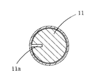
可動鉄心11は、図3に示すように、前述のようにパイプ8の内周面に摺動可能に嵌合されるように丸状に形成され、一部に軸方向に沿って油溝11aが形成されている。従って、固定鉄心9側から流入された油は可動鉄心11の油溝11aを通ってパイプ8内に循環されることになる。また、可動鉄心11の前端面には、固定鉄心9の凹部9cに係合する凸部11bが形成されている。そして、コイル6の励磁によって固定鉄心9に吸着され、コイル6の励磁を解除することによって、図示しないばねの付勢力でパイプ8のストッパ部82に向かって摺動する。
【0017】
上記のように構成される電磁石1は、外ケース3のフランジ部3aを、例えば油圧弁体に取り付けることによって油圧電磁弁を構成する。この場合、可動鉄心9弁体との間には弁体のスプールを移動させるためのピン(図示せず)が固定鉄心9の貫通孔9dに挿通されながら配設されている。上記のピンは丸状で両面に切欠面が形成されているため、貫通孔9dとピンの切欠面との間から油が電磁石1側に流入される。そして、コイル6を励磁すると、固定鉄心9・可動鉄心11・ヨーク13・外ケース3に磁界が発生し、可動鉄心11は固定鉄心9に吸着する方向に移動して、固定鉄心9の凹部9cに可動鉄心11の凸部11bを係合させる。
【0018】
コイル6の励磁が解除されると、固定鉄心9と可動鉄心11との間には磁界が消磁するため、図示しないばねにより前記ピンを介して可動鉄心11が固定鉄心9から離隔する方向に移動することになる。
【0019】
従って、この電磁石1は、パイプ8の後端部にプレス加工されたストッパ部82が円筒部本体81に溶接にて一体的に形成されているので、特にパイプ8の円筒部本体81を新たに加工する必要がなく、パイプ8を廉価に製作できる。しかも従来のナットを削除することができ、電磁石1内に流入された油のシール箇所を、固定鉄心9とパイプ8とに配設されたOリング17の1箇所だけですみ、この点においてもコストの低減を図ることができる。
【0020】
なお、固定鉄心9とパイプ8との間に配設されるOリング17は、油洩れ防止の役目をするとともに、固定鉄心9とパイプ8との固着作用の役目をも行なっている。しかし、これに限らず、固定鉄心9とパイプ8との合わせ面において、溶接したりまたはロー付・カシメ等で固着することによって、油洩れ防止や固着作用を行なってもよい。
【0021】
さらに、本発明は特に、電磁石のチューブアッシー内の改良を主としているため、コイルアッシーの形態は上記に限るものではない。
【0022】
【発明の効果】
本発明によれば、電磁石は、一端が開口される外ケースとコイルが巻回される中空状のボビンとを有するコイルアッシーと、前記コイルアッシーに収納されパイプ及び固定鉄心・可動鉄心を有するチューブアッシーと、を備え、前記可動鉄心が前記コイルの励磁によって作動されるように構成されるものであり、
前記パイプが中空状に形成され、前記固定鉄心と前記可動鉄心とを収納する本体部と、前記パイプ内の一方を塞ぐように配設されるストッパ部と、を有して形成され、前記ストッパ部が、中央部において前記パイプ内に向かって突起する突起部と、外周部において前記パイプ外に向かって突起する顎部と、を有して形成され、前記顎部が前記パイプの端面に係合するとともに、前記顎部の外周面が前記パイプの外周面と略同径に形成されている。従って、特にパイプ8の円筒部本体を新たに加工する必要がなく、パイプ8を廉価に製作できる。しかも従来のナットを削除することができるとともに、電磁石1内に流入された油のシール箇所を少なくすることができ、この点においてもコストの低減を図ることができる。さらに、可動鉄心がパイプのストッパ部に接触する際に油で密着することを防止しているので、可動鉄心の速やかな摺動が維持される。
【図面の簡単な説明】
【図1】本発明の一形態による電磁石を示す正面断面図
【図2】図1におけるパイプの一部を示す詳細断面図
【図3】図1における可動鉄心の断面図
【図4】従来の電磁石を示す断面図
【符号の説明】
1…電磁石
2…コイルアッシー
3…外ケース
5…ボビン
6…コイル
7…チューブアッシー
8…パイプ
9…固定鉄心
11…可動鉄心
13…ヨーク
15…座板
17…Oリング
81…円筒部本体
82…ストッパ部
82a…本体部
82b…突起部
82c…顎部
82d…係止部[0001]
BACKGROUND OF THE INVENTION
The present invention has a coil assembly and a tube assembly accommodated in the coil assembly, and the movable core disposed in the tube assembly is fixed to the fixed core side by excitation of the coil disposed in the coil assembly. The present invention relates to an electromagnet configured to be slidable.
[0002]
[Prior art]
Conventionally, an electromagnet has a bobbin formed in a hollow shape, a magnetic coil wound around the bobbin, a fixed iron core disposed in the bobbin, and a movable iron core that is slidably moved away from the fixed iron core. And. In general, the movable iron core is operated so as to be attracted to the fixed iron core by excitation of a magnetic coil.
[0003]
The
[0004]
A through
[0005]
[Problems to be solved by the invention]
However, if price competition becomes fierce, the price of conventional electromagnets must be reviewed. In particular, the oil-immersed
[0006]
The present invention solves the above-mentioned problems, and in particular, by changing the shape of the stopper of the pipe, it is possible to manufacture the stopper at a low cost and eliminate the conventional nut, thereby reducing the cost. The purpose is to provide.
[0007]
[Means for Solving the Problems]
The electromagnet according to the present invention is configured as follows to solve the above problems. That is,
A coil assembly including an outer case having one end opened and a hollow bobbin around which a coil is wound; and a tube assembly housed in the coil assembly and having a pipe and a fixed iron core / movable iron core, the movable iron core Is an electromagnet configured to be activated by excitation of the coil,
The pipe is formed in a hollow shape, and has a cylindrical portion main body that houses the fixed iron core and the movable iron core, and a stopper portion that is disposed so as to close one of the pipes.
The stopper part is formed in a stepped disk shape having a stopper part body part, and protrudes from the stopper part body part into the pipe in order to reduce a contact area with the movable iron core in the center part. And a jaw portion protruding from the stopper portion main body portion toward the outside of the pipe at the outer peripheral portion, and the jaw portion engages with an end surface of the pipe, and the outer periphery of the jaw portion The surface is formed to have substantially the same diameter as the outer peripheral surface of the cylindrical body of the pipe.
[0008]
DETAILED DESCRIPTION OF THE INVENTION
Hereinafter, an embodiment of the present invention will be described with reference to the drawings.
[0009]
As shown in FIG. 1, the
[0010]
The
[0011]
The
[0012]
As shown in FIG. 2, the
[0013]
As shown in FIG. 2, the
[0014]
And the wave-
[0015]
The fixed
[0016]
As shown in FIG. 3, the
[0017]
The
[0018]
When the excitation of the
[0019]
Accordingly, the
[0020]
The O-
[0021]
Furthermore, since the present invention mainly focuses on improvements in the tube assembly of the electromagnet, the form of the coil assembly is not limited to the above.
[0022]
【The invention's effect】
According to the present invention, an electromagnet includes a coil assembly having an outer case whose one end is open and a hollow bobbin around which a coil is wound, and a tube having a pipe, a fixed iron core and a movable iron core housed in the coil assembly. An assembly, and the movable iron core is configured to be activated by excitation of the coil,
The pipe is formed in a hollow shape, and has a main body portion that houses the fixed iron core and the movable iron core, and a stopper portion that is disposed so as to close one of the pipes, and the stopper A projection portion projecting toward the inside of the pipe at a central portion and a jaw portion projecting toward the outside of the pipe at an outer peripheral portion, and the jaw portion is engaged with an end surface of the pipe. In addition, the outer peripheral surface of the jaw portion is formed to have substantially the same diameter as the outer peripheral surface of the pipe. Therefore, it is not necessary to newly process the cylindrical portion main body of the
[Brief description of the drawings]
FIG. 1 is a front sectional view showing an electromagnet according to an embodiment of the present invention. FIG. 2 is a detailed sectional view showing a part of a pipe in FIG. 1. FIG. 3 is a sectional view of a movable iron core in FIG. Sectional view showing electromagnet 【Explanation of symbols】
DESCRIPTION OF
Claims (1)
前記パイプが中空状に形成され、前記固定鉄心と前記可動鉄心とを収納する円筒部本体と、前記パイプ内の一方を塞ぐように配設されるストッパ部と、を有して形成され、
前記ストッパ部が、ストッパ部本体部を有する段付円板状に形成され、中央部において前記可動鉄心との接触面積を少なくするために前記ストッパ部本体部から前記パイプ内に向かって突起する突起部と、外周部において前記ストッパ部本体部から前記パイプ外に向かって突起する顎部と、を有して形成され、前記顎部が前記パイプの端面に係合するとともに、前記顎部の外周面が前記パイプの円筒部本体の外周面と略同径に形成されることを特徴とする電磁石。A coil assembly including an outer case having one end opened and a hollow bobbin around which a coil is wound; and a tube assembly housed in the coil assembly and having a pipe and a fixed iron core / movable iron core, the movable iron core Is an electromagnet configured to be activated by excitation of the coil,
The pipe is formed in a hollow shape, and has a cylindrical portion main body that houses the fixed iron core and the movable iron core, and a stopper portion that is disposed so as to close one of the pipes.
The stopper part is formed in a stepped disk shape having a stopper part body part, and protrudes from the stopper part body part into the pipe in order to reduce a contact area with the movable iron core in the center part. And a jaw portion protruding from the stopper portion main body portion toward the outside of the pipe at the outer peripheral portion, and the jaw portion engages with an end surface of the pipe, and the outer periphery of the jaw portion An electromagnet characterized in that the surface is formed to have substantially the same diameter as the outer peripheral surface of the cylindrical body of the pipe.
Priority Applications (1)
| Application Number | Priority Date | Filing Date | Title |
|---|---|---|---|
| JP16297497A JP3661118B2 (en) | 1997-06-19 | 1997-06-19 | electromagnet |
Applications Claiming Priority (1)
| Application Number | Priority Date | Filing Date | Title |
|---|---|---|---|
| JP16297497A JP3661118B2 (en) | 1997-06-19 | 1997-06-19 | electromagnet |
Publications (2)
| Publication Number | Publication Date |
|---|---|
| JPH1116722A JPH1116722A (en) | 1999-01-22 |
| JP3661118B2 true JP3661118B2 (en) | 2005-06-15 |
Family
ID=15764828
Family Applications (1)
| Application Number | Title | Priority Date | Filing Date |
|---|---|---|---|
| JP16297497A Expired - Lifetime JP3661118B2 (en) | 1997-06-19 | 1997-06-19 | electromagnet |
Country Status (1)
| Country | Link |
|---|---|
| JP (1) | JP3661118B2 (en) |
-
1997
- 1997-06-19 JP JP16297497A patent/JP3661118B2/en not_active Expired - Lifetime
Also Published As
| Publication number | Publication date |
|---|---|
| JPH1116722A (en) | 1999-01-22 |
Similar Documents
| Publication | Publication Date | Title |
|---|---|---|
| US20090072174A1 (en) | Solenoid valve | |
| US20060097830A1 (en) | Solenoid-actuated air valve | |
| JPH0559307B2 (en) | ||
| US6604726B2 (en) | Proportional solenoid-controlled fluid valve assembly without non-magnetic alignment support element | |
| JP3661118B2 (en) | electromagnet | |
| US20060043326A1 (en) | Solenoid valve with spherical armature | |
| JP3752647B2 (en) | Fixing method of tube and fixed iron core in electromagnet | |
| JPH1116721A (en) | Electromagnet | |
| JP3333988B2 (en) | Solenoid for hydraulic solenoid valve | |
| JP3185099B2 (en) | electromagnet | |
| JPH1047526A (en) | Valve block equipped with at least one washer faced valve to be electromagnetically controlled | |
| US20050092376A1 (en) | Three port -two way solenoid valve | |
| JPH1116723A (en) | Electromagnet | |
| JP3185100B2 (en) | electromagnet | |
| JP3755073B2 (en) | Solenoid for solenoid valve | |
| JP2004263823A (en) | Solenoid valve | |
| JPH04145268A (en) | Pressing-in and locking method of spherical valve element into plunger | |
| JP3182572B2 (en) | solenoid | |
| JPS6141122B2 (en) | ||
| JPH1140421A (en) | Electromagnet | |
| JP3185098B2 (en) | electromagnet | |
| JPH1197239A (en) | Hydraulic electromagnetic valve solenoid | |
| US11948737B2 (en) | Solenoid | |
| JPH1022123A (en) | Detent type electromagnetic valve | |
| US11908620B2 (en) | Solenoid |
Legal Events
| Date | Code | Title | Description |
|---|---|---|---|
| A977 | Report on retrieval |
Free format text: JAPANESE INTERMEDIATE CODE: A971007 Effective date: 20041005 |
|
| A131 | Notification of reasons for refusal |
Free format text: JAPANESE INTERMEDIATE CODE: A131 Effective date: 20041124 |
|
| A521 | Written amendment |
Free format text: JAPANESE INTERMEDIATE CODE: A523 Effective date: 20050112 |
|
| TRDD | Decision of grant or rejection written | ||
| A01 | Written decision to grant a patent or to grant a registration (utility model) |
Free format text: JAPANESE INTERMEDIATE CODE: A01 Effective date: 20050208 |
|
| A61 | First payment of annual fees (during grant procedure) |
Free format text: JAPANESE INTERMEDIATE CODE: A61 Effective date: 20050309 |
|
| R150 | Certificate of patent or registration of utility model |
Free format text: JAPANESE INTERMEDIATE CODE: R150 |
|
| FPAY | Renewal fee payment (event date is renewal date of database) |
Free format text: PAYMENT UNTIL: 20110401 Year of fee payment: 6 |
|
| FPAY | Renewal fee payment (event date is renewal date of database) |
Free format text: PAYMENT UNTIL: 20120401 Year of fee payment: 7 |
|
| FPAY | Renewal fee payment (event date is renewal date of database) |
Free format text: PAYMENT UNTIL: 20130401 Year of fee payment: 8 |
|
| FPAY | Renewal fee payment (event date is renewal date of database) |
Free format text: PAYMENT UNTIL: 20140401 Year of fee payment: 9 |
|
| R250 | Receipt of annual fees |
Free format text: JAPANESE INTERMEDIATE CODE: R250 |
|
| R250 | Receipt of annual fees |
Free format text: JAPANESE INTERMEDIATE CODE: R250 |
|
| R250 | Receipt of annual fees |
Free format text: JAPANESE INTERMEDIATE CODE: R250 |
|
| R250 | Receipt of annual fees |
Free format text: JAPANESE INTERMEDIATE CODE: R250 |
|
| EXPY | Cancellation because of completion of term |