JP3660189B2 - Igniter - Google Patents
Igniter Download PDFInfo
- Publication number
- JP3660189B2 JP3660189B2 JP2000058122A JP2000058122A JP3660189B2 JP 3660189 B2 JP3660189 B2 JP 3660189B2 JP 2000058122 A JP2000058122 A JP 2000058122A JP 2000058122 A JP2000058122 A JP 2000058122A JP 3660189 B2 JP3660189 B2 JP 3660189B2
- Authority
- JP
- Japan
- Prior art keywords
- high voltage
- electrode
- discharge
- igniter
- voltage terminal
- Prior art date
- Legal status (The legal status is an assumption and is not a legal conclusion. Google has not performed a legal analysis and makes no representation as to the accuracy of the status listed.)
- Expired - Lifetime
Links
Images


Description
【0001】
【産業上の利用分野】
本発明は、石油やガスを使用した暖房器具や給湯機等のバーナへの点火源として使用される、燃焼器具用イグナイタに関する。
【0002】
【従来の技術】
一般的に、イグナイタは、合成樹脂で形成された筐体と金属で形成された放電電極部で構成され、前記筐体内部には、高電圧を発生するための電子部品が配線基板に搭載されている。必要に応じて、当該配線基板に搭載された電子部品は、ポリウレタン系の樹脂を使って前記筐体内部を樹脂充填しモールドしている。前記筐体には、入力端子と、出力端子があり、入力端子には前記電子部品の電源となる、一次電圧を印加し、出力端子は当該一次電圧を受けて、二次側から高電圧を出力する。当該二次側から発生した高電圧を、放電電極部に供給し、図示はしていないが、バーナから供給される噴霧状態の燃料に、火花放電を発生させることにより、燃料を着火するものである。例えば、石油ファンヒータにおいて、電源スイッチをオンにすると、前記バーナの電源がオンとなり、燃料の石油が空気中に噴霧される。続いて、イグナイタの電源がオンとなり、当該イグナイタの出力端子から、約20KVピークの高電圧が発生し、当該高電圧は放電電極部に供給されて、放電部で火花放電を発生する。当該放電部とバーナには間隙があり、前記火花放電を受けて、空気中に噴霧された燃料である石油に着火する。前記バーナの燃料が着火すると、センサで温度を検出し、確実に着火したことを検知し一定の時間経過後、イグナイタの電源をオフにする。
【0003】
従来例のイグナイタを図5に示し、高電圧出力部18の断面図と放電電極部30の側面図を示す図5において、高電圧出力部18には、イグナイタ10の筐体12に、筐体貫通孔22が形成されている。当該筐体貫通孔22は、外部との絶縁距離を確保するために、前記筐体貫通孔22の外周に、隔壁となる筐体壁面26が形成されている。前記筐体貫通孔22の内部からネジ14が、当該筐体貫通孔22の外部に挿通し、外部にてナット16で固着されている。当該ナット16の上部には、バネ端子20が圧入され、前記筐体12の高電圧出力部18として形成される。また、前記ネジ14の前記筐体12の内部には、図示しない配線基板からの高電圧出力リード24が接続されている。
【0004】
次に、イグナイタ10の放電電極部30の構成について説明する。当該放電電極部30は、導体部42の一端に、高電圧の火花放電を発生させるための放電部40が形成され、他端はネジ部34が形成されている。当該ネジ部34と前記放電部40の間の任意の位置には、絶縁部38が形成されている。前記導体部40と前記絶縁部38は、一体成形により固着され、前記ネジ部34に、L形の金属板で加工された電極接続部32が挿入され、当該電極接続部32はナット36で固着されている。なお、放電部40とネジ部34は、導体部42と一体で構成され、絶縁部38は碍子等の絶縁物で構成されている。前記高電圧出力部18と前記放電電極部30の接続は、電極接続部32を図5のE方向へ、押圧することにより、バネ端子20と接触させる。
【0005】
イグナイタ10の前記高電圧出力部18と、前記放電電極部30は、図5の背面側に一定の間隙をおいて平行に、同じ構成の高電圧出力部18と放電電極部30が奥に形成され、2つで一対となり、イグナイタ10としての働きをしている。ただし、放電部40は、火花放電をおこなうためのギャップを形成するため、当該放電部40-40は、2〜5mmの間隙を設け形成される。また、高電圧を接続するバネ端子20-20と電極接続部32-32は、筐体12と放電電極部30をそれぞれ固定し、押圧により接続される。
【0006】
次に、前記イグナイタ10の筐体12と放電電極部30の電気的動作について説明する。図示はしていないが、配線基板に搭載された電子部品により、高電圧が発生され、当該高電圧が高電圧出力リード24-24に供給される。前記高電圧は、前記高電圧出力リード24-24からネジ14-14を経由して、前記バネ端子20-20に供給され、前記バネ端子20-20は、押圧されている前記電極接続部32-32に供給され、さらに前記高電圧は、ネジ部34-34、導体部42-42を経由して、放電部40-40に供給される。当該放電部40-40に発生した高電圧は、図示はしていないが、前記放電部40-40間に2〜5mmのギャップを形成し、前記放電部40-40間で火花放電が開始される。
【0007】
【発明が解決しようとする課題】
筐体12の高電圧出力部18において、図示はしていないが、高電圧を出力する配線基板からの接続は、高電圧出力リード24で行っているために、当該高電圧リード24の浮遊容量により出力電圧が不安定になったり、低下すると言った問題がある。また、前記高電圧出力部18は、前述の通り、筐体貫通孔22にネジ14を挿通し、ナット16、バネ端子20を組み付けることにより構成されているが、当該組み付け作業に時間がかかり効率が悪く、部品点数も多いために、コストが高くついていた。
【0008】
また、前記放電電極部30においても、電極接続部32をナット36で固着したり、導体部42の他端にネジ部34を形成するため、ネジ加工をおこなうと言った、効率の悪い作業が発生し、且つ、前記高電圧出力部18と同様、コストが高くついていた。
【0009】
本発明は、上記課題に鑑みてなされたもので、上記高電圧出力部18と放電電極部30の組立性をそれぞれ簡素化し、性能を劣化させることなく、安価なイグナイタ10を提供することを目的とする。
【0010】
【課題を解決するための手段】
上記課題を解決するために、本発明においては、高電圧出力を備えたイグナイタ50の筐体52と放電電極部60において、前記筐体52は高圧筒55に固着された高圧端子54と高圧コイル58とを備え、前記高圧端子54と前記高圧コイル58を直接接続し、前記放電電極部60は導体部42の一端に電極接続部62を設け、前記高圧端子54に前記電極接続部62を挿入することを特徴とするイグナイタを提供する。
【0011】
【発明の実施の形態】
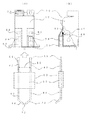
本発明の実施例とするイグナイタを図1に示し、当該図1の(A)は正面図、(B)は側面図(ともに一部切欠断面図)を示している。図1において、イグナイタ50の筐体52は合成樹脂で形成され、当該筐体52内部には、図示はしていないが、高電圧を発生するための電子部品が配線基板に搭載されている。必要に応じて、当該配線基板に搭載された電子部品は、ポリウレタン系の樹脂を使って前記筐体52内部を樹脂充填しモールドしている。前記イグナイタ50には、入力端子53と高圧端子54-54が形成され、前記入力端子53には前記電子部品の一次電圧を印加し、当該一次電圧を受けて、二次側に昇圧した高電圧が、前記高圧端子54-54に出力される。本発明の実施例では、入力端子53に100Vの交流電圧を印加すると、高圧端子54-54には約20KVピークのパルス性の交流電圧が発生する。
【0012】
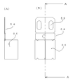
イグナイタ50の筐体52内に組み込まれている、高圧端子54-54について構成を説明する。図1の高圧端子の拡大図を示す図2において(A)は側面図、(B)は正面図を示し、図2の高圧端子のA−A断面図を図3に示す。前記高圧端子54は、ステンレス、リン青銅等の弾性のある金属で構成され、形状は長方形で、一端は高圧部の接続となる接続固定部59が形成され、他端は、長方体をした外縁部86から構成されている。当該外縁部86には、図3の断面図に示すように、第1の屈設部80-80と、当該第1の屈設部80-80の延長線上に設けられた第2の屈設部82-82で構成された弾性部90-90と、図1の電極接続部62-62が挿入されたときに当接するための、電極当接部84が設けられている。前記第1の屈設部80-80と前記第2の屈設部82-82で構成された前記弾性部90-90は、左右対称に2枚形成され、図1の電極接続部62を左右から挟み込むようになっている。なお、高圧端子54は、1枚ものの弾性部材の、折り曲げ加工により作製することができる。
【0013】
図1に示す前記高圧端子54-54は、高圧筒55-55に前記高圧端子54-54の一端である接続固定部59-59を先頭に当接するまで挿入する。本発明の実施例では、前記高圧端子54-54と高圧筒55-55の挿入は、圧入により実施しているが溶着、接着、抜け防止部の設置等により実施することが可能である。前記高圧端子54-54を前記高圧筒55-55に挿入すると、前記高圧端子54-54の接続固定部59-59は、筐体52内部に入り込み、当該筐体52内の高圧コイル58の端子57-57と接触する。当該高圧コイル58の端子57-57と前記接続固定部59-59の接続は、半田付け、溶接、カシメ等により機械的に接続される。
【0014】
次に、イグナイタ50の放電電極部60の構成について説明する。当該放電電極部60は、任意の電極ピッチ56を設定した2本の導体部42-42を設け、当該導体部42-42の一端は矩形の電極接続部62-62を形成し、他端は任意の角度を持ったギャップ72で構成された放電部70-70が形成されている。前記導体部42-42中央付近の任意の位置には、当該導体部42-42を固定するために、碍子等で構成された、絶縁部68が前記導体部42-42と一体成形される。本発明の実施例において、導体部42-42の形状は丸形で構成され、電極接続部62-62は、前記導体部42の丸形の形状を、プレス加工により矩形とし、放電部70-70の先端は、円錐状に加工し火花放電が起きやすい形状としている。なお、導電部42-42の形状は、今回丸形にて説明したが、丸形以外でも三角形、正方形、長方形、多角形であっても実施可能であることは、言うまでもない。また、本発明の実施例では、電極ピッチ56は20〜28mm、ギャップ72は2〜5mmに設定している。
【0015】
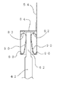
次に、イグナイタ50の筐体52の高圧端子54-54と、放電電極部60の接続方法について説明する。前記筐体52の前記高圧端子54-54と、放電電極部60の放電接続部62-62を、図1(A)のD方向に挿入する。図1の高圧端子と電極接続部の挿入実施例を示す図4において、前記電極接続部62の挿入により、弾性部90-90が開き、電極当接部84で当接する。当該当接状態において、前記電極接続部62と前記高圧端子54の弾性部90-90は、第1の屈設部80-80と第2の屈設部82-82の押圧により保持される。当該電極接続部62の押圧の保持力は、9.8〜19.6Nとなり、本発明で使用するには十分な保持力が確保される。
【0016】
本発明のイグナイタ50の筐体52と放電電極部60の構成および接続方法について説明をしたが、以下前記筐体52と前記放電電極部60の電気的なつながりを説明する。前記筐体52の入力端子53に、電源となる交流100Vを印加すると、図示はしていないが、配線基板に搭載された電子部品に電圧が供給され、約20KVピークのパルス性の交流の高電圧が高圧コイル58-58に発生する。当該高圧コイル58-58に発生した高電圧は、高圧端子54-54に供給され、さらに、図4のように前記高圧端子54-54から電極接続部62-62に供給される。当該電極接続部62-62に供給された高電圧は、図1に示すように導体部42-42を通過し、放電部70-70のギャップ72で火花放電をおこす。図示はしていないが、前記火花放電により、空気中にバーナから噴霧された燃料である石油に着火する。
【0017】
【発明の効果】
本発明により、従来の図5の、筐体12と放電電極部30に比べ、高圧コイル58からの高電圧を最短距離で伝達する事ができるため、出力電圧が不安定になったり、当該電圧が低下すると言った不具合が解消される。また、従来例では高電圧出力部18の筐体貫通孔22に、高電圧出力リード24、ネジ14、ナット16、バネ端子20を使用して組み付け作業を行っていたが、本発明により、高圧端子54を高圧コイル58に直接接続することができ、組立工数の削減および部品コストも大きく下げることができる。また、放電電極部60についても、放電接続部62に従来例のようなナットを使用しないで、導体部42を一体加工することにより、前記放電電極部60の組み立ての簡素化を可能にし、前記筐体52の組み立て同様、組立工数および部品コストの削減ができる。
【図面の簡単な説明】
【図1】本発明の実施例とするイグナイタ
【図2】図1の高圧端子の拡大図
【図3】図2の高圧端子のA−A断面図
【図4】図1の高圧端子と電極接続部の挿入実施例
【図5】従来例のイグナイタ
【符号の説明】
図において同一符号は、同一または相当部分を表す。
10、50 イグナイタ
12、52 筐体
14 ネジ
16、36 ナット
18 高電圧出力部
20 バネ端子
22 筐体貫通孔
24 高電圧出力リード
26 筐体壁面
30、60 放電電極部
32、62 電極接続部
34 ネジ部
38、68 絶縁部
40、70 放電部
42 導体部
53 入力端子
54 高圧端子
55 高圧筒
56 電極ピッチ
57 端子
58 高圧コイル
59 接続固定部
72 ギャップ
80 第1の屈設部
82 第2の屈設部
84 電極当接部
86 外縁部
90 弾性部[0001]
[Industrial application fields]
The present invention relates to an igniter for a combustion appliance that is used as an ignition source for a burner such as a heating appliance or a water heater using oil or gas.
[0002]
[Prior art]
Generally, an igniter is composed of a case made of synthetic resin and a discharge electrode part made of metal, and an electronic component for generating a high voltage is mounted on the wiring board inside the case. ing. If necessary, the electronic component mounted on the wiring board is molded by filling the inside of the housing with a polyurethane resin. The housing has an input terminal and an output terminal. A primary voltage is applied to the input terminal as a power source for the electronic component. The output terminal receives the primary voltage and receives a high voltage from the secondary side. Output. Although not shown, the high voltage generated from the secondary side is supplied to the discharge electrode unit, and the fuel is ignited by generating a spark discharge in the sprayed fuel supplied from the burner. is there. For example, in an oil fan heater, when a power switch is turned on, the power of the burner is turned on, and fuel oil is sprayed into the air. Subsequently, the power of the igniter is turned on, and a high voltage of about 20 KV peak is generated from the output terminal of the igniter. The high voltage is supplied to the discharge electrode part, and a spark discharge is generated in the discharge part. There is a gap between the discharge section and the burner, and the spark discharge is received to ignite petroleum, which is fuel sprayed in the air. When the fuel of the burner is ignited, the temperature is detected by a sensor, and the ignition is surely detected. After a predetermined time has elapsed, the igniter is turned off.
[0003]
A conventional igniter is shown in FIG. 5, and in FIG. 5, which shows a cross-sectional view of the high voltage output unit 18 and a side view of the discharge electrode unit 30, the high voltage output unit 18 includes the case 12 of the igniter 10. A through hole 22 is formed. The casing through-hole 22 is formed with a casing wall surface 26 as a partition wall on the outer periphery of the casing through-hole 22 in order to ensure an insulation distance from the outside. A screw 14 is inserted from the inside of the housing through-hole 22 to the outside of the housing through-hole 22 and fixed with a nut 16 on the outside. A spring terminal 20 is press-fitted into the upper portion of the nut 16 and is formed as a high voltage output portion 18 of the housing 12. A high voltage output lead 24 from a wiring board (not shown) is connected to the inside of the housing 12 of the screw 14.
[0004]
Next, the configuration of the discharge electrode unit 30 of the igniter 10 will be described. In the discharge electrode portion 30, a discharge portion 40 for generating a high voltage spark discharge is formed at one end of the conductor portion 42, and a screw portion 34 is formed at the other end. An insulating part 38 is formed at an arbitrary position between the screw part 34 and the discharge part 40. The conductor portion 40 and the insulating portion 38 are fixed by integral molding, and an electrode connection portion 32 processed with an L-shaped metal plate is inserted into the screw portion 34. The electrode connection portion 32 is fixed by a nut 36. Has been. In addition, the discharge part 40 and the screw part 34 are comprised integrally with the conductor part 42, and the insulation part 38 is comprised with insulators, such as an insulator. The high voltage output unit 18 and the discharge electrode unit 30 are brought into contact with the spring terminal 20 by pressing the electrode connection unit 32 in the direction E of FIG.
[0005]
The high voltage output unit 18 and the discharge electrode unit 30 of the igniter 10 are formed in parallel with a certain gap on the back side in FIG. The two are paired and serve as the igniter 10. However, since the discharge part 40 forms a gap for performing spark discharge, the discharge part 40-40 is formed with a gap of 2 to 5 mm. Further, the spring terminal 20-20 and the electrode connection portion 32-32 for connecting a high voltage are connected by pressing the casing 12 and the discharge electrode portion 30, respectively.
[0006]
Next, the electrical operation of the casing 12 and the discharge electrode unit 30 of the igniter 10 will be described. Although not shown, a high voltage is generated by electronic components mounted on the wiring board, and the high voltage is supplied to the high voltage output leads 24-24. The high voltage is supplied from the high voltage output lead 24-24 via the screw 14-14 to the spring terminal 20-20, and the spring terminal 20-20 is pressed. The high voltage is further supplied to the discharge part 40-40 via the screw part 34-34 and the conductor part 42-42. Although the high voltage generated in the discharge unit 40-40 is not illustrated, a gap of 2 to 5 mm is formed between the discharge units 40-40, and spark discharge is started between the discharge units 40-40. The
[0007]
[Problems to be solved by the invention]
In the high voltage output unit 18 of the housing 12, although not shown, since the connection from the wiring board that outputs a high voltage is performed by the high voltage output lead 24, the stray capacitance of the high voltage lead 24 is As a result, the output voltage becomes unstable or decreases. Further, as described above, the high voltage output unit 18 is configured by inserting the screw 14 through the housing through hole 22 and assembling the nut 16 and the spring terminal 20. However, the assembling work takes time and efficiency. However, the cost was high due to the large number of parts.
[0008]
Also, in the discharge electrode portion 30, the electrode connecting portion 32 is fixed with the nut 36, or the screw portion 34 is formed on the other end of the conductor portion 42, so that inefficient work such as performing screw processing is performed. As with the high voltage output unit 18, the cost is high.
[0009]
The present invention has been made in view of the above problems, and aims to provide an inexpensive igniter 10 without simplifying the assembly of the high voltage output unit 18 and the discharge electrode unit 30 and degrading the performance. And
[0010]
[Means for Solving the Problems]
In order to solve the above problems, in the present invention, in the casing 52 and the discharge electrode portion 60 of the igniter 50 having a high voltage output, the casing 52 is fixed to a high voltage cylinder 55 and a high voltage coil. 58, directly connecting the high-voltage terminal 54 and the high-voltage coil 58, the discharge electrode portion 60 is provided with an electrode connection portion 62 at one end of the conductor portion 42, and the electrode connection portion 62 is inserted into the high-voltage terminal 54 An igniter is provided.
[0011]
DETAILED DESCRIPTION OF THE INVENTION
FIG. 1 shows an igniter according to an embodiment of the present invention. FIG. 1A is a front view, and FIG. 1B is a side view (both are partially cutaway sectional views). In FIG. 1, a casing 52 of an igniter 50 is formed of a synthetic resin, and an electronic component for generating a high voltage is mounted on the wiring board inside the casing 52, although not shown. If necessary, the electronic component mounted on the wiring board is molded by filling the inside of the casing 52 with a polyurethane resin. The igniter 50 is formed with an input terminal 53 and a high voltage terminal 54-54. A high voltage obtained by applying a primary voltage of the electronic component to the input terminal 53 and receiving the primary voltage and boosting it to the secondary side. Is output to the high-voltage terminals 54-54. In the embodiment of the present invention, when an AC voltage of 100 V is applied to the input terminal 53, a pulsed AC voltage having a peak of about 20 KV is generated at the high voltage terminals 54-54.
[0012]
The configuration of the high-voltage terminals 54-54 incorporated in the casing 52 of the igniter 50 will be described. 2A and 2B, which are enlarged views of the high-voltage terminal in FIG. 1, FIG. 3A is a side view, FIG. 2B is a front view, and FIG. The high-voltage terminal 54 is made of an elastic metal such as stainless steel or phosphor bronze, has a rectangular shape, has one end formed with a connection fixing portion 59 to be connected to the high-pressure portion, and the other end has a rectangular shape. It consists of an outer edge 86. As shown in the cross-sectional view of FIG. 3, the outer edge portion 86 has a first bent portion 80-80 and a second bent portion provided on an extension line of the first bent portion 80-80. An electrode abutting portion 84 for abutting when the elastic portion 90-90 constituted by the portions 82-82 and the electrode connecting portion 62-62 of FIG. 1 are inserted is provided. Two elastic portions 90-90 formed of the first bent portion 80-80 and the second bent portion 82-82 are formed symmetrically so that the electrode connecting portion 62 of FIG. It is supposed to be sandwiched from. The high voltage terminal 54 can be manufactured by bending a single elastic member.
[0013]
The high-voltage terminal 54-54 shown in FIG. 1 is inserted into the high-pressure cylinder 55-55 until a connection fixing portion 59-59 which is one end of the high-voltage terminal 54-54 comes into contact with the head. In the embodiment of the present invention, the insertion of the high-voltage terminals 54-54 and the high-pressure cylinders 55-55 is performed by press-fitting, but can be performed by welding, adhesion, installation of a removal preventing part, or the like. When the high-voltage terminal 54-54 is inserted into the high-pressure cylinder 55-55, the connection fixing portion 59-59 of the high-voltage terminal 54-54 enters the housing 52, and the terminal of the high-voltage coil 58 in the housing 52 Contact 57-57. The connection between the terminals 57-57 of the high voltage coil 58 and the connection fixing portions 59-59 is mechanically connected by soldering, welding, caulking or the like.
[0014]
Next, the configuration of the discharge electrode unit 60 of the igniter 50 will be described. The discharge electrode portion 60 is provided with two conductor portions 42-42 having an arbitrary electrode pitch 56, one end of the conductor portion 42-42 forms a rectangular electrode connection portion 62-62, and the other end is Discharge portions 70-70 constituted by gaps 72 having an arbitrary angle are formed. In order to fix the conductor part 42-42 at an arbitrary position near the center of the conductor part 42-42, an insulating part 68 made of an insulator or the like is integrally formed with the conductor part 42-42. In the embodiment of the present invention, the conductor part 42-42 has a round shape, and the electrode connecting part 62-62 has a round shape of the conductor part 42 formed into a rectangle by press working, and the discharge part 70- The tip of 70 is processed into a conical shape and spark discharge is likely to occur. Although the shape of the conductive portions 42-42 has been described as a round shape this time, it goes without saying that the present invention can be applied to a shape other than the round shape, such as a triangle, a square, a rectangle, and a polygon. In the embodiment of the present invention, the electrode pitch 56 is set to 20 to 28 mm, and the gap 72 is set to 2 to 5 mm.
[0015]
Next, a method for connecting the high-voltage terminals 54-54 of the casing 52 of the igniter 50 and the discharge electrode unit 60 will be described. The high-voltage terminals 54-54 of the casing 52 and the discharge connection portions 62-62 of the discharge electrode portion 60 are inserted in the direction D in FIG. In FIG. 4 showing an insertion example of the high-voltage terminal and the electrode connecting portion in FIG. 1, the elastic portion 90-90 is opened by the insertion of the electrode connecting portion 62 and is brought into contact with the electrode contact portion 84. In this contact state, the electrode connecting portion 62 and the elastic portion 90-90 of the high-voltage terminal 54 are held by the pressing of the first bent portion 80-80 and the second bent portion 82-82. The pressing holding force of the electrode connecting portion 62 is 9.8 to 19.6 N, and a holding force sufficient for use in the present invention is ensured.
[0016]
Although the configuration and connection method of the casing 52 and the discharge electrode unit 60 of the igniter 50 of the present invention have been described, the electrical connection between the casing 52 and the discharge electrode unit 60 will be described below. When AC 100V serving as a power source is applied to the input terminal 53 of the casing 52, although not shown, a voltage is supplied to an electronic component mounted on the wiring board, and a pulsed AC high voltage of about 20 KV peak is supplied. A voltage is developed across the high voltage coils 58-58. The high voltage generated in the high voltage coil 58-58 is supplied to the high voltage terminal 54-54, and is further supplied from the high voltage terminal 54-54 to the electrode connection part 62-62 as shown in FIG. The high voltage supplied to the electrode connection portions 62-62 passes through the conductor portions 42-42 as shown in FIG. 1, and causes a spark discharge in the gap 72 of the discharge portions 70-70. Although not shown, the spark discharge ignites oil which is fuel sprayed from the burner in the air.
[0017]
【The invention's effect】
According to the present invention, the high voltage from the high voltage coil 58 can be transmitted in the shortest distance compared to the case 12 and the discharge electrode portion 30 of FIG. The problem of lowering is resolved. Moreover, in the conventional example, the high voltage output lead 24, the screw 14, the nut 16, and the spring terminal 20 were used to assemble the housing through hole 22 of the high voltage output unit 18, but according to the present invention, a high voltage Since the terminal 54 can be directly connected to the high voltage coil 58, the number of assembling steps can be reduced and the component cost can be greatly reduced. Also, for the discharge electrode portion 60, without using a nut as in the conventional example for the discharge connection portion 62, by integrally processing the conductor portion 42, it is possible to simplify the assembly of the discharge electrode portion 60, Similar to the assembly of the casing 52, the number of assembly steps and the cost of parts can be reduced.
[Brief description of the drawings]
1 is an igniter according to an embodiment of the present invention. FIG. 2 is an enlarged view of a high-voltage terminal in FIG. 1. FIG. 3 is a cross-sectional view taken along line AA of the high-voltage terminal in FIG. Example of insertion of connecting part [Fig. 5] Conventional igniter [Explanation of symbols]
In the figures, the same reference numerals represent the same or corresponding parts.
10, 50 Igniter 12, 52 Housing 14 Screw 16, 36 Nut 18 High voltage output 20 Spring terminal 22 Housing through hole 24 High voltage output lead 26 Housing wall 30, 60 Discharge electrode 32, 62 Electrode connection 34 Screw portion 38, 68 Insulating portion 40, 70 Discharge portion 42 Conductor portion 53 Input terminal 54 High voltage terminal 55 High voltage cylinder 56
Claims (5)
Priority Applications (1)
| Application Number | Priority Date | Filing Date | Title |
|---|---|---|---|
| JP2000058122A JP3660189B2 (en) | 2000-03-03 | 2000-03-03 | Igniter |
Applications Claiming Priority (1)
| Application Number | Priority Date | Filing Date | Title |
|---|---|---|---|
| JP2000058122A JP3660189B2 (en) | 2000-03-03 | 2000-03-03 | Igniter |
Publications (2)
| Publication Number | Publication Date |
|---|---|
| JP2001248838A JP2001248838A (en) | 2001-09-14 |
| JP3660189B2 true JP3660189B2 (en) | 2005-06-15 |
Family
ID=18578766
Family Applications (1)
| Application Number | Title | Priority Date | Filing Date |
|---|---|---|---|
| JP2000058122A Expired - Lifetime JP3660189B2 (en) | 2000-03-03 | 2000-03-03 | Igniter |
Country Status (1)
| Country | Link |
|---|---|
| JP (1) | JP3660189B2 (en) |
Families Citing this family (2)
| Publication number | Priority date | Publication date | Assignee | Title |
|---|---|---|---|---|
| CN100510538C (en) | 2003-08-22 | 2009-07-08 | 株式会社能率 | Ignition unit |
| IT1400683B1 (en) | 2010-07-06 | 2013-06-28 | Castfutura Spa | IGNITION DEVICE FOR BOILERS OR SIMILAR. |
-
2000
- 2000-03-03 JP JP2000058122A patent/JP3660189B2/en not_active Expired - Lifetime
Also Published As
| Publication number | Publication date |
|---|---|
| JP2001248838A (en) | 2001-09-14 |
Similar Documents
| Publication | Publication Date | Title |
|---|---|---|
| CN103647219A (en) | High power discharge fuel ignitor | |
| JP3267097B2 (en) | Electrical connection member, internal combustion engine ignition device using electrical connection member, and method of manufacturing the same | |
| JP4956830B2 (en) | High pressure discharge lamp and lighting device | |
| JP3660189B2 (en) | Igniter | |
| EP1101067A1 (en) | Electronic gas-lighting device integrated with a terminal board | |
| JP4377252B2 (en) | Ignition coil with connecting device for contact with spark plug | |
| US6506047B1 (en) | Fast-fit electronic gas-lighting device | |
| TW353183B (en) | Electric component and variable resistor for high voltage use | |
| WO2004107501B1 (en) | Arrester disconnector assembly having a capacitor and a resistor | |
| US5677596A (en) | Plug with radiation screening element | |
| JP2003194333A (en) | Ignition unit and method for mounting the same | |
| EP0222336A2 (en) | Piezoelectric gas igniter | |
| JP4308146B2 (en) | Igniter short-circuit contact | |
| JP3597587B2 (en) | Ignition device | |
| JPH11250726A (en) | Compact low-voltage discharge lamp | |
| JPS6350597Y2 (en) | ||
| JPS6330043Y2 (en) | ||
| JP2007198643A (en) | Discharge ignition device for burning appliance | |
| JPH0438540Y2 (en) | ||
| JP2010038138A (en) | Plasma ignition device | |
| SU1288800A1 (en) | Glow plug operating in contact-breaking mode | |
| KR19980030817U (en) | Combination structure of spark plug and connector | |
| EP0969251A3 (en) | Ignition apparatus for boiler | |
| JP2005098631A (en) | Discharge ignition device for combustion appliance | |
| JP2002071133A (en) | Igniter and method for connecting terminal of igniter |
Legal Events
| Date | Code | Title | Description |
|---|---|---|---|
| A131 | Notification of reasons for refusal |
Free format text: JAPANESE INTERMEDIATE CODE: A131 Effective date: 20040525 |
|
| A521 | Written amendment |
Free format text: JAPANESE INTERMEDIATE CODE: A523 Effective date: 20040716 |
|
| TRDD | Decision of grant or rejection written | ||
| A01 | Written decision to grant a patent or to grant a registration (utility model) |
Free format text: JAPANESE INTERMEDIATE CODE: A01 Effective date: 20050315 |
|
| A61 | First payment of annual fees (during grant procedure) |
Free format text: JAPANESE INTERMEDIATE CODE: A61 Effective date: 20050316 |
|
| R150 | Certificate of patent or registration of utility model |
Free format text: JAPANESE INTERMEDIATE CODE: R150 Ref document number: 3660189 Country of ref document: JP Free format text: JAPANESE INTERMEDIATE CODE: R150 |
|
| FPAY | Renewal fee payment (event date is renewal date of database) |
Free format text: PAYMENT UNTIL: 20080325 Year of fee payment: 3 |
|
| FPAY | Renewal fee payment (event date is renewal date of database) |
Free format text: PAYMENT UNTIL: 20090325 Year of fee payment: 4 |
|
| R250 | Receipt of annual fees |
Free format text: JAPANESE INTERMEDIATE CODE: R250 |
|
| FPAY | Renewal fee payment (event date is renewal date of database) |
Free format text: PAYMENT UNTIL: 20090325 Year of fee payment: 4 |
|
| FPAY | Renewal fee payment (event date is renewal date of database) |
Free format text: PAYMENT UNTIL: 20100325 Year of fee payment: 5 |
|
| R250 | Receipt of annual fees |
Free format text: JAPANESE INTERMEDIATE CODE: R250 |
|
| FPAY | Renewal fee payment (event date is renewal date of database) |
Free format text: PAYMENT UNTIL: 20100325 Year of fee payment: 5 |
|
| FPAY | Renewal fee payment (event date is renewal date of database) |
Free format text: PAYMENT UNTIL: 20120325 Year of fee payment: 7 |
|
| R250 | Receipt of annual fees |
Free format text: JAPANESE INTERMEDIATE CODE: R250 |
|
| FPAY | Renewal fee payment (event date is renewal date of database) |
Free format text: PAYMENT UNTIL: 20120325 Year of fee payment: 7 |
|
| R250 | Receipt of annual fees |
Free format text: JAPANESE INTERMEDIATE CODE: R250 |
|
| FPAY | Renewal fee payment (event date is renewal date of database) |
Free format text: PAYMENT UNTIL: 20140325 Year of fee payment: 9 |
|
| R250 | Receipt of annual fees |
Free format text: JAPANESE INTERMEDIATE CODE: R250 |
|
| FPAY | Renewal fee payment (event date is renewal date of database) |
Free format text: PAYMENT UNTIL: 20140325 Year of fee payment: 9 |
|
| R250 | Receipt of annual fees |
Free format text: JAPANESE INTERMEDIATE CODE: R250 |
|
| R250 | Receipt of annual fees |
Free format text: JAPANESE INTERMEDIATE CODE: R250 |
|
| R250 | Receipt of annual fees |
Free format text: JAPANESE INTERMEDIATE CODE: R250 |
|
| R250 | Receipt of annual fees |
Free format text: JAPANESE INTERMEDIATE CODE: R250 |
|
| R250 | Receipt of annual fees |
Free format text: JAPANESE INTERMEDIATE CODE: R250 |
|
| R250 | Receipt of annual fees |
Free format text: JAPANESE INTERMEDIATE CODE: R250 |
|
| EXPY | Cancellation because of completion of term |