JP3660108B2 - Image storage method and machine-readable medium - Google Patents
Image storage method and machine-readable medium Download PDFInfo
- Publication number
- JP3660108B2 JP3660108B2 JP23409597A JP23409597A JP3660108B2 JP 3660108 B2 JP3660108 B2 JP 3660108B2 JP 23409597 A JP23409597 A JP 23409597A JP 23409597 A JP23409597 A JP 23409597A JP 3660108 B2 JP3660108 B2 JP 3660108B2
- Authority
- JP
- Japan
- Prior art keywords
- image
- projection
- spherical surface
- memory
- plane
- Prior art date
- Legal status (The legal status is an assumption and is not a legal conclusion. Google has not performed a legal analysis and makes no representation as to the accuracy of the status listed.)
- Expired - Fee Related
Links
- 238000000034 method Methods 0.000 title claims description 20
- 238000010586 diagram Methods 0.000 description 6
- 238000007726 management method Methods 0.000 description 5
- 238000004364 calculation method Methods 0.000 description 4
- 230000006870 function Effects 0.000 description 3
- 239000011159 matrix material Substances 0.000 description 3
- 239000000203 mixture Substances 0.000 description 3
- 238000006243 chemical reaction Methods 0.000 description 2
- 239000002131 composite material Substances 0.000 description 2
- 230000000694 effects Effects 0.000 description 2
- 238000003384 imaging method Methods 0.000 description 2
- 230000003287 optical effect Effects 0.000 description 2
- 230000009466 transformation Effects 0.000 description 2
- PCTMTFRHKVHKIS-BMFZQQSSSA-N (1s,3r,4e,6e,8e,10e,12e,14e,16e,18s,19r,20r,21s,25r,27r,30r,31r,33s,35r,37s,38r)-3-[(2r,3s,4s,5s,6r)-4-amino-3,5-dihydroxy-6-methyloxan-2-yl]oxy-19,25,27,30,31,33,35,37-octahydroxy-18,20,21-trimethyl-23-oxo-22,39-dioxabicyclo[33.3.1]nonatriaconta-4,6,8,10 Chemical compound C1C=C2C[C@@H](OS(O)(=O)=O)CC[C@]2(C)[C@@H]2[C@@H]1[C@@H]1CC[C@H]([C@H](C)CCCC(C)C)[C@@]1(C)CC2.O[C@H]1[C@@H](N)[C@H](O)[C@@H](C)O[C@H]1O[C@H]1/C=C/C=C/C=C/C=C/C=C/C=C/C=C/[C@H](C)[C@@H](O)[C@@H](C)[C@H](C)OC(=O)C[C@H](O)C[C@H](O)CC[C@@H](O)[C@H](O)C[C@H](O)C[C@](O)(C[C@H](O)[C@H]2C(O)=O)O[C@H]2C1 PCTMTFRHKVHKIS-BMFZQQSSSA-N 0.000 description 1
- 230000015572 biosynthetic process Effects 0.000 description 1
- 238000013500 data storage Methods 0.000 description 1
- 238000000605 extraction Methods 0.000 description 1
- 238000003786 synthesis reaction Methods 0.000 description 1
- 230000002194 synthesizing effect Effects 0.000 description 1
Images


Description
【0001】
【発明の属する技術分野】
本発明は、電子的に表現された画像の処理に係り、特に、デジタルカメラ等で異なった方位を撮影した画像の貼り合わせ合成等の分野に関する。
【0002】
【従来の技術】
デジタルカメラ等の撮影機器は視野や解像度が限定されているため、より高解像度の画像、広角の画像、パノラマ画像等を得るには、異なった方位を撮影した複数枚の画像を貼り合わせて合成する方法が有効である。
【0003】
パノラマ画像を例にとると、現在のところ、複数の画像を貼り合わせて得られるのは、単一方向(ある地点から見て天球上の円を描く方向)のパノラマ画像に限られている。このようなパノラマ画像の作成手法の一例を図6により簡単に説明する。
【0004】
ある地点からデジタルカメラで撮影した画像Gの各画素(a,b等)を、デジタルカメラのレンズ中心cを中心軸とした円筒面300に投影する。a′,b′は画素a,bの円筒面300上に投影された点である。デジタルカメラのレンズ中心cを固定したまま、デジタルカメラの光軸をOa′を含む平面(通常は水平面)に平行に移動させながら、つまり、その方向にデジタルカメラを振りながら、360゜のシーンを分割撮影し、各方位で撮影された画像の画素を円筒面300に投影する。このように複数枚の画像を円筒面300に投影して貼り合わせることにより、360゜のパノラマ画像を合成することができる。このパノラマ画像をディスプレイの画面に表示する場合には、観測したい視線方向と垂直な平面を定義し、この平面上に円筒面300上の画素を再投影する。画像データの記憶・管理については、複数の画像が投影された円筒面300を展開した長方形又は正方形に対応したメモリ空間を用意し、ここに円筒面300上に投影された全ての画素の情報を記憶させることにより、360゜のパノラマ画像のデータを一括してメモリに記憶し、効率的に管理することができる。
【0005】
単一方向のパノラマ画像については、上に述べたような手法によって合成し、また、その画像データを一括して効率的に記憶・管理することができる。しかし、カメラ位置の周りの任意の方位を撮影した複数の画像を貼り合わせて、例えば全天をカバーするような3次元的なパノラマ画像を合成し、またその画像データを一括して効率的に記憶・管理するための実用的な手法は、これまで公知になっていない。
【0006】
【発明が解決しようとする課題】
上に述べた3次元的なパノラマ画像等の合成に関して、発明者等は、同じ地点からデジタルカメラ等で撮影した複数の画像を、カメラのレンズ中心を中心とした球面上に投影して貼り合わせる手法を既に提案している(特願平9−166737号)。
【0007】
この手法を実施する場合、画像データの保存・管理に問題が残されている。すなわち、球面は円筒面のように簡便に展開することができないため、円筒面に投影された画像データのような簡単な方法では、球面上に投影して貼り合わせた画像のデータを一括して効率的に保存・管理することができない。
【0008】
合成前の個々の画像のデータを別々にメモリに記憶しておき、ある方位について画像を観測したい時に、その方位の視野に含まれる画像を球面に投影して貼り合わせ、それを表示平面に再投影するという方法を採用することも可能である。しかし、表示の都度、画像合成を行うのでは表示までに時間がかかってしまい、短時間内に連続的に方位を変えて画像を観測することは困難である。
【0009】
高速の画像表示を可能にするために、一定の空間角度間隔の多くの方位について予め画像合成を行い、それぞれの合成画像のデータを別々にメモリに記憶しておき、観測したい方位の合成画像を表示する方法も考えられる。しかし、この方法では、画像データの記憶のために必要なメモリ量が大きいうえに画像データの管理が面倒である。さらに、予め用意されていない方位の画像の表示が困難である。
【0010】
よって本発明の目的は、上に述べた3次元的パノラマ画像等の少ないメモリ量による効率的な保存・管理及び高速な画像再現を可能にする方法を提供することにある。
【0011】
【課題を解決するための手段】
本発明は、球面上に投影された画像を、その球面と交差する平面へ平射投影し、その平射投影画像のデータを一括してメモリ又は記録媒体に格納する。
【0012】
この方法によれば、例えば、デジタルカメラ等で同じ位置から任意の方位を撮影した複数の画像を球面に投影して貼り合わせた3次元的パノラマ画像のデータを一括してメモリ又は記録媒体上に保存し、一つのファイルとして管理することができる。このようにすれば、様々な方位の合成画像を別々のファイルとして保存する方法に比べ、必要なメモリ量は遥かに少なくて済み、また、メモリ又は記録媒体上の画像データの管理も簡単になる。また、メモリ又は記録媒体上の画像(既に合成されたパノラマ画像)を球面に再投影し、その必要な視野部分をさらに表示平面に投影することにより、任意の方位について画像を高速に表示することができる。
【0013】
【発明の実施の形態】
以下、図面を参照し、本発明の一実施例について詳細に説明する。
【0014】
図1は本発明の一実施例による処理の概要を示すフローチャートである。図2,図3及び図4は処理の説明のための図である。
【0015】
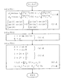
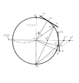
まず、初めのステップS1において、例えばデジタルカメラで一地点から異なった方位を撮影した複数の画像(要素画像と呼ぶ)を、図2に示すようなデジタルカメラのレンズと撮像面までの距離に等しい半径Rを持ちレンズ中心を中心Oとした球面100に投影して貼り合わせ、一つの合成画像を球面100上に作る。図2において、F1は球面100に投影される一つの要素画像であり、pはその一つの画素である。Nは中心Oから見て真上にある球面の極であり、ここでは北極と呼ぶ。Sは中心Oから見て真下にある球面の極であり、ここでは南極と呼ぶ。102は北極Nと南極Sを結ぶ垂直な線であり、ここでは極軸と呼ぶ。104は中心Oを通る水平な面であり、ここでは赤道面と呼ぶ。Qは画素pの投影された点を通る経度線と赤道面104との交差点である。線分Oxは経度の基準線であり、例えば東の方位を指す。φは基準線Oxに対し線分OQのなす角度であり、画素pの経度と呼ぶ。θは中心Oから画素pを望む視線と極軸102とのなす角度である。一般的には、赤道面からの仰角を緯度というが、ここでは極軸102との角度θを画素pの緯度と呼ぶ。つまり、θ=90゜−[一般的な意味の緯度]である。
【0016】
このステップS1では、具体的には例えば以下のような座標演算を行う。デジタルカメラにより撮影された要素画像の各画素の位置は、その光軸(通常は中心)を原点とした直交座標系で表されるのが一般的である。そこで、まず、(1)式により、要素画像の各画素の座標(i,j)を方位角座標(φx′,φy′)に一旦変換する。ただし、(1)式において、Rは要素画像を撮影したデジタルカメラのレンズと撮像面の距離、つまり球面100の半径である。次に、(2)式により、要素画像の各画素の方位角座標を、統一された基準座標系の方位角座標(φ,θ)に変換する。(2)式において、φとθは図2に関連して説明した経度と緯度である。また、(2)式中のAは2つの座標系間の変換マトリックスである。このような座標変換マトリックスは、例えば前記特願平9−166737号の明細書に詳述されているように、隣り合う要素画像のオーバーラップ領域の対応点間の相対的位置関係に基づいて導出することができる。座標変換マトリックスAを求めるため、要素画像は隣接したもの同士が部分的にオーバーラップするように撮影される。
【0017】
次のステップS2において、球面100に投影され貼り合わされた画像を、赤道面104を含む平面106(図3)に平射投影する。この平射投影は、具体的には、球面100上の各画素の座標(φ,θ)を、(3)式に従って、極座標
(r,Φ)に変換することによって行う。
【0018】
図3は、図1の画素pの投影点と点Qを通る経度線で球面100を輪切りにした断面図である。106は赤道面104を含む平射投影平面である。O′は要素画像F1の中心、p′は要素画像F1上の画素pの球面100への投影点である。この点p′が平射投影により赤道面を含む平面106に投影された点がp″である。
【0019】
水平線より上のシーンだけを対象にするならば、球面100の赤道面104より上の半球面(北半球面)に投影された画像だけを平射投影すればよく、全ての画素は赤道面104の内部に投影される。しかし、図3に見られるように、デジタルカメラ等で水平方向を撮影した要素画像F2には赤道面104より下の部分も写っており、そのような部分の画素は平射投影により赤道面104より外側に投影される。例えば、要素画像F2の画素qは、球面100上の点q′に投影され、さらに平射投影により平面106上の点q″に投影される。wは要素画像F2上の最も下に位置する画素であり、球面100上の点w′に投影され、さらに平面106上の点w″に投影される。本実施例では、平射投影平面106を赤道面104より広げることによって、水平方向より上のシーンのみならず、水平方向よりある角度だけ下方向のシーンも、その画像データを一つのファイルとして記憶できるようにする。
【0020】
図4は、平射投影平面106上の画像投影領域と、その画像データの記憶領域とを関連付けて説明するための図である。球面100の北半球面上の画素は円110で示される範囲に平射投影される。球面100上の赤道面104より下側の一定範囲までの画素を投影するために、平射投影領域は円112で示す領域まで拡大される。したがって、円110と円112の間の領域は球面100の南半球面の一部(北半球面と連続している)の画像が投影される領域である。
【0021】
図1に戻る。最後のステップS3において、前ステップS2により平射投影された画像のデータを一括してメモリに記憶する。具体的には、本実施例では以下のような操作を行って画像データをメモリに記憶させる。
【0022】
まず、図4に示す平射投影平面上の正方形ABCD領域に対応したメモリ領域を確保する。前ステップS2では平射投影された各画素位置は極座標(r,Φ)で表現されているが、一般にメモりロケーションには整数番地が付けられる。そこで、平射投影された各画素の座標を(4)式により直交座標(X,Y)に変換する。次に実数座標(X,Y)を(5)式により整数座標(I,J)に変換する。なお、(5)式において、[x]はxを超えない最大の整数を意味する。
【0023】
このようにして求めた整数座標(I,J)に対応する番地のメモリロケーションに、例えば(6)式の補間演算により計算した画素値もしくは輝度値f(I,J)を書き込む。(6)式において、f(Xi,Yj)は実数座標(Xi,Yj)における計算上の画素値もしくは輝度値である。Ip( )は補間関数で、例えば線形補間関数やキュービック(Cubic)補間関数である。この補間演算は、注目した整数座標(I,J)の周囲の一定距離の範囲内、例えば(7)式の範囲内で行う(ただしThは定数)。
【0024】
このようにして、球面100の北半球面及びそれに連続した南半球面の一部に投影され貼り合わせられた画像のデータを一括してメモリに記憶し、一つのファイルとして管理することができる。
【0025】
一般に、コンピュータによりメモリ上のデータを効率よく管理するためには、その番地範囲が簡単な記号で表せることが望ましい。2次元番地(I,J)の場合、A<I<B、C<J<Dのような区間による管理が最も一般的である。本実施例は、そのような要求を満たす。
【0026】
また、画像データを扱う場合、演算処理の均一性や画像表現の精度の面で、メモリ上で連続する画素は実空間上でもほぼ等しい間隔であること、つまり、メモリ上の画素(I,J)と画素(I,J+1)の実空間上での間隔が、メモリ上の画素(I,J+1)と画素(I,J+2)の実空間上での間隔とほぼ等しいことが望まれる。本実施例では、メモリ上に配列される画素は、球面上の画素とほぼ同一オーダーの密度で分布するので(中心付近と周辺での密度の差は最大で1:4である)、上の要求を満たす。
【0027】
以上のようにしてメモリに記憶された画像を再現する場合には、画像を記憶する場合と丁度逆の変換過程によってメモリ上の画素を球面に投影し、観測したい方位に垂直な平面へ再投影すればよい。要素画像の合成は済んでいるから、任意の方位の画像を、高速に再現できる。
【0028】
なお、高い山の頂上や高層ビルの屋上からのシーンを撮影し、そのパノラマ画像を得たい場合、水平方向よりかなり下方のシーンまで対象範囲に含めたいことがある。気球やヘリコプターからシーンを撮影し、そのパノラマ画像を得たい場合には、真下のシーンまで対象範囲に含めたい。このように、水平方向からどの程度下方まで処理の対象にしたらよいか一律に決定することが難しい場合には、球面の上半分(北半球面)に投影された画像と、下半分(南半球面)に投影された画像とをそれぞれ別々に赤道面に平射投影し、各平射投影画像をそれぞれメモリに記憶し一つのファイルとして管理するとよい。このようにしても、上に述べた過程によって再現できる。これも本発明の一つの実施例である。
【0029】
以上に説明した本発明の処理は、例えば図5に示すようなCPU200、メモリ201、ディスプレイ装置202、ユーザ入力装置(キーボード、マウス等)203、ハードディスク装置204、フロッピーディスク装置205、PCカード読み取り装置206等をシステムバス207で接続した構成のコンピュータ上でプログラムによって実現できる。例えば、デジタルカメラによって、ある地点から撮影されPCカード208に記録された一連の画像のデータは、PCカード読み取り装置206によってコンピュータに読み込まれ、ハードディスク装置204に格納される。図1に関連して説明した本発明の処理のためのプログラム210は、例えばフロッピーディスク装置205にセットされたフロッピーディスク209より読み込まれてハードディスク装置204に格納され、必要な時点でメモリ201にロードされて実行される。このプログラム210の実行時に、処理の対象となる画像のデータがハードディスク装置204からメモリ201に読み込まれる。処理に必要なメモリ領域、例えば図1のステップS3で平射投影画像データが書き込まれるメモリ領域211は、必要な時点でメモリ201上に確保される。このメモリ領域211に書き込まれた平射投影画像データは必要に応じてハードディスク装置204又はフロッピーディスク209に保存され、画像再現時に再びメモリ201に読み込まれる。
【0030】
以上に述べたように、本発明によれば、3次元的なパノラマ画像等の保存に必要なメモリ量の削減及び高速の画像再現が可能になるが、さらに異地点から撮影した一連の画像の相互の比較、演算が容易になる。例えば、撮影者がある地点で周囲のシーンを撮影した一連の画像と、場所を移動して周囲のシーンを撮影した一連の画像とを比較し、被写体の遠近情報を測定する場合、両地点から撮影された一連の画像は統一された座標系で表現されているのが望ましい。本発明は一地点から撮影した一連の画像を平射投影表現するが、例えば垂直方向を投影座標系の中心点にとり、水平面を投影座標系の円周にとり、そして、ある方位を基準軸にとれば、異地点から撮影された画像中の対応する被写体の方位(視差)を座標の差として直接的に表現できるため、遠近情報の抽出が容易になる。
【0031】
【発明の効果】
以上に説明したように、本発明によれば、同一位置から異なった方位を撮影した複数の画像を合成した3次元的パノラマ画像等のデータの効率的な保存・管理及び高速な画像再現が可能となり、また、異地点から撮影した一連の画像の相互の比較による被写体の遠近情報の抽出が容易になる等の効果を得られる。
【図面の簡単な説明】
【図1】本発明の一実施例による処理の概略を示すフローチャートである。
【図2】要素画像の球面投影を説明するための図である。
【図3】図2をある経度線で輪切りにした断面図である。
【図4】画像の平射投影領域とメモリ領域を関連付けて示す図である。
【図5】本発明の処理を実施するためのコンピュータの一例を示すブロック図である。
【図6】円筒面への投影によるパノラマ画像作成の説明図である。
【符号の説明】
100 球面
102 極軸
104 赤道面
106 平射投影平面
F1,F2 要素画像
O 中心
N 北極
S 南極
Φ 経度
θ 緯度
p,q,w 要素画像上の画素
p′,q′,w′ 球面上への投影点
p″,q″,w″ 平射投影点
200 CPU
201 メモリ
202 ディスプレイ装置
203 ユーザ入力装置
204 ハードディスク装置
205 フロッピーディスク装置
206 PCカード読み取り装置
207 システムバス
208 PCカード
209 フロッピーディスク
210 プログラム
211 メモリ領域[0001]
BACKGROUND OF THE INVENTION
The present invention relates to processing of an electronically expressed image, and more particularly to the field of combining and combining images taken from different orientations with a digital camera or the like.
[0002]
[Prior art]
Since photography devices such as digital cameras have limited fields of view and resolution, in order to obtain higher resolution images, wide-angle images, panoramic images, etc., multiple images taken from different directions are combined and combined. The method to do is effective.
[0003]
Taking a panoramic image as an example, at present, only a panoramic image in a single direction (direction of drawing a circle on a celestial sphere when viewed from a certain point) can be obtained by pasting a plurality of images. An example of such a panoramic image creation method will be briefly described with reference to FIG.
[0004]
Each pixel (a, b, etc.) of the image G taken by the digital camera from a certain point is projected onto the
[0005]
Unidirectional panoramic images can be synthesized by the method described above, and the image data can be efficiently stored and managed collectively. However, a plurality of images taken from any orientation around the camera position are pasted together to synthesize a three-dimensional panoramic image that covers the whole sky, for example, and the image data can be efficiently and collectively A practical technique for storing and managing has not been known so far.
[0006]
[Problems to be solved by the invention]
Regarding the composition of the above-described three-dimensional panoramic image, etc., the inventors project a plurality of images taken with a digital camera or the like from the same point onto a spherical surface centered on the lens center of the camera and paste them together. A method has already been proposed (Japanese Patent Application No. 9-166737).
[0007]
When this method is implemented, there remains a problem in storing and managing image data. In other words, since a spherical surface cannot be developed as easily as a cylindrical surface, in a simple method such as image data projected on a cylindrical surface, the data of images projected and pasted on the spherical surface are batched. It cannot be stored and managed efficiently.
[0008]
The data of each image before composition is stored separately in the memory, and when you want to observe the image in a certain direction, project and paste the images contained in the field of view of that direction onto the spherical surface, and re-display it on the display plane. It is also possible to employ a method of projecting. However, if image composition is performed each time it is displayed, it takes time to display, and it is difficult to observe images while continuously changing the orientation within a short time.
[0009]
In order to enable high-speed image display, image synthesis is performed in advance for many azimuths at a certain spatial angular interval, and data of each synthesized image is stored separately in a memory, and a synthesized image of the azimuth to be observed is stored. A display method is also conceivable. However, this method requires a large amount of memory for storing image data, and management of image data is troublesome. Furthermore, it is difficult to display an image having a direction that is not prepared in advance.
[0010]
Accordingly, an object of the present invention is to provide a method that enables efficient storage / management and high-speed image reproduction with a small memory amount such as the above-described three-dimensional panoramic image.
[0011]
[Means for Solving the Problems]
According to the present invention, an image projected on a spherical surface is projected onto a plane intersecting with the spherical surface, and the data of the projected projection image is collectively stored in a memory or a recording medium.
[0012]
According to this method, for example, data of a three-dimensional panoramic image obtained by projecting a plurality of images photographed in an arbitrary direction from the same position with a digital camera or the like onto a spherical surface and pasting them together is stored on a memory or a recording medium. Save and manage as one file. In this way, compared to the method of saving composite images of various orientations as separate files, the amount of memory required is much smaller, and the management of image data on the memory or recording medium becomes easier. . In addition, the image on the memory or the recording medium (the panoramic image that has already been synthesized) is re-projected onto the spherical surface, and the necessary field of view is further projected onto the display plane, so that the image can be displayed at high speed in any orientation. Can do.
[0013]
DETAILED DESCRIPTION OF THE INVENTION
Hereinafter, an embodiment of the present invention will be described in detail with reference to the drawings.
[0014]
FIG. 1 is a flowchart showing an outline of processing according to an embodiment of the present invention. 2, 3 and 4 are diagrams for explaining the processing.
[0015]
First, in the first step S1, for example, a plurality of images (referred to as elemental images) taken from different points from one point with a digital camera are equal to the distance between the lens of the digital camera and the imaging surface as shown in FIG. Projecting and pasting onto a
[0016]
Specifically, in this step S1, for example, the following coordinate calculation is performed. In general, the position of each pixel of an element image photographed by a digital camera is represented by an orthogonal coordinate system with the optical axis (usually the center) as the origin. Therefore, first, the coordinates (i, j) of each pixel of the element image are once converted into azimuth coordinates (φx ′, φy ′) by the equation (1). In equation (1), R is the distance between the lens of the digital camera that captured the element image and the imaging surface, that is, the radius of the
[0017]
In the next step S <b> 2, the image projected and pasted on the
[0018]
FIG. 3 is a cross-sectional view of the
[0019]
If only the scene above the horizon is targeted, only the image projected onto the hemisphere (north hemisphere) above the
[0020]
FIG. 4 is a diagram for explaining the image projection area on the
[0021]
Returning to FIG. In the last step S3, the data of the images projected by the normal projection in the previous step S2 are collectively stored in the memory. Specifically, in this embodiment, the following operation is performed to store the image data in the memory.
[0022]
First, a memory area corresponding to the square ABCD area on the orthogonal projection plane shown in FIG. 4 is secured. In the previous step S2, each pixel position projected orthogonally is expressed by polar coordinates (r, Φ), but generally an integer address is assigned to the memory location. Therefore, the coordinates of each pixel projected by plane projection are converted into orthogonal coordinates (X, Y) by the equation (4). Next, the real number coordinates (X, Y) are converted into integer coordinates (I, J) by the equation (5). In the formula (5), [x] means the maximum integer not exceeding x.
[0023]
For example, the pixel value or luminance value f (I, J) calculated by the interpolation calculation of equation (6) is written in the memory location at the address corresponding to the integer coordinates (I, J) obtained in this way. In equation (6), f (Xi, Yj) is a calculated pixel value or luminance value in real number coordinates (Xi, Yj). Ip () is an interpolation function, for example, a linear interpolation function or a cubic interpolation function. This interpolation calculation is performed within a fixed distance around the focused integer coordinates (I, J), for example, within the range of the expression (7) (where Th is a constant).
[0024]
In this way, the data of the image projected and pasted onto the northern hemisphere of the
[0025]
Generally, in order to efficiently manage data on a memory by a computer, it is desirable that the address range can be expressed by a simple symbol. In the case of a two-dimensional address (I, J), management by a section such as A <I <B and C <J <D is most common. The present embodiment satisfies such a requirement.
[0026]
In the case of handling image data, in terms of the uniformity of arithmetic processing and the accuracy of image representation, continuous pixels on the memory are almost equally spaced in the real space, that is, the pixels (I, J on the memory). ) And the pixel (I, J + 1 ) in the real space is desired to be substantially equal to the space in the real space between the pixel (I, J + 1) and the pixel (I, J + 2) in the memory. In this embodiment, the pixels arranged on the memory are distributed with a density of almost the same order as the pixels on the spherical surface (the difference in density between the vicinity of the center and the periphery is 1: 4 at the maximum). Satisfy the request.
[0027]
When reproducing the image stored in the memory as described above, the pixel on the memory is projected onto the spherical surface by a conversion process just opposite to the case of storing the image, and then re-projected onto the plane perpendicular to the direction to be observed. do it. Since the element images have been combined, an image in an arbitrary direction can be reproduced at high speed.
[0028]
When shooting a scene from the top of a high mountain or the roof of a high-rise building and obtaining a panoramic image thereof, there are cases where it is desired to include the scene considerably below the horizontal direction in the target range. If you want to capture a panoramic image of a scene from a balloon or helicopter, you want to include the scene just below. In this way, when it is difficult to uniformly determine how much processing should be performed from the horizontal direction, the image projected on the upper half (north hemisphere) of the sphere and the lower half (south hemisphere) It is preferable to project the images projected on the equatorial plane separately onto the equator plane and store each projected projection image in a memory and manage it as a single file. This can also be reproduced by the process described above. This is also one embodiment of the present invention.
[0029]
The processing of the present invention described above includes, for example, a
[0030]
As described above, according to the present invention, it is possible to reduce the amount of memory necessary for storing a three-dimensional panoramic image and the like and to reproduce the image at high speed. Mutual comparison and calculation become easy. For example, when measuring the perspective information of a subject by comparing a series of images taken of a surrounding scene at a certain point with a series of images taken of the surrounding scene by moving the place, It is desirable that a series of captured images be expressed in a unified coordinate system. In the present invention, a series of images taken from a single point are represented by projection projection. For example, if the vertical direction is taken as the center point of the projection coordinate system, the horizontal plane is taken as the circumference of the projection coordinate system, and a certain direction is taken as the reference axis. Since the orientation (parallax) of the corresponding subject in the image taken from a different point can be directly expressed as a difference in coordinates, the perspective information can be easily extracted.
[0031]
【The invention's effect】
As described above, according to the present invention, it is possible to efficiently store and manage data such as a three-dimensional panoramic image obtained by synthesizing a plurality of images taken from the same position and different directions, and to perform high-speed image reproduction. In addition, it is possible to obtain an effect of facilitating extraction of perspective information of a subject by comparing a series of images taken from different points.
[Brief description of the drawings]
FIG. 1 is a flowchart showing an outline of processing according to an embodiment of the present invention.
FIG. 2 is a diagram for explaining spherical projection of an element image.
FIG. 3 is a cross-sectional view of FIG. 2 cut along a longitude line.
FIG. 4 is a diagram showing an orthographic projection area of an image and a memory area in association with each other.
FIG. 5 is a block diagram illustrating an example of a computer for executing processing according to the present invention.
FIG. 6 is an explanatory diagram of panorama image creation by projection onto a cylindrical surface.
[Explanation of symbols]
100
201
Claims (4)
Priority Applications (1)
| Application Number | Priority Date | Filing Date | Title |
|---|---|---|---|
| JP23409597A JP3660108B2 (en) | 1997-08-29 | 1997-08-29 | Image storage method and machine-readable medium |
Applications Claiming Priority (1)
| Application Number | Priority Date | Filing Date | Title |
|---|---|---|---|
| JP23409597A JP3660108B2 (en) | 1997-08-29 | 1997-08-29 | Image storage method and machine-readable medium |
Publications (2)
| Publication Number | Publication Date |
|---|---|
| JPH1173489A JPH1173489A (en) | 1999-03-16 |
| JP3660108B2 true JP3660108B2 (en) | 2005-06-15 |
Family
ID=16965551
Family Applications (1)
| Application Number | Title | Priority Date | Filing Date |
|---|---|---|---|
| JP23409597A Expired - Fee Related JP3660108B2 (en) | 1997-08-29 | 1997-08-29 | Image storage method and machine-readable medium |
Country Status (1)
| Country | Link |
|---|---|
| JP (1) | JP3660108B2 (en) |
Families Citing this family (7)
| Publication number | Priority date | Publication date | Assignee | Title |
|---|---|---|---|---|
| WO2004036498A1 (en) * | 2002-10-15 | 2004-04-29 | Seiko Epson Corporation | Panorama synthesis processing of a plurality of image data |
| JP2007226580A (en) * | 2006-02-24 | 2007-09-06 | Advanced Telecommunication Research Institute International | Image output device and image output method |
| WO2011121741A1 (en) * | 2010-03-30 | 2011-10-06 | 富士通株式会社 | Image generation device, image generation program, synthesis table generation device, and synthesis table generation program |
| JP5790345B2 (en) | 2011-09-07 | 2015-10-07 | 株式会社リコー | Image processing apparatus, image processing method, program, and image processing system |
| JP6184831B2 (en) * | 2013-10-17 | 2017-08-23 | 株式会社アウトソーシングテクノロジー | Exit pupil position measuring device, imaging device, exit pupil position measuring method and program, and imaging method and program |
| CN105869110B (en) | 2016-03-28 | 2018-09-28 | 腾讯科技(深圳)有限公司 | The method for customizing and device of method for displaying image and device, abnormal curved surface curtain |
| JP6798183B2 (en) * | 2016-08-04 | 2020-12-09 | 株式会社リコー | Image analyzer, image analysis method and program |
-
1997
- 1997-08-29 JP JP23409597A patent/JP3660108B2/en not_active Expired - Fee Related
Also Published As
| Publication number | Publication date |
|---|---|
| JPH1173489A (en) | 1999-03-16 |
Similar Documents
| Publication | Publication Date | Title |
|---|---|---|
| US7426317B2 (en) | Image processing apparatus and image processing method, storage medium and computer program | |
| US10593014B2 (en) | Image processing apparatus, image processing system, image capturing system, image processing method | |
| JP5490040B2 (en) | Digital 3D / 360 degree camera system | |
| US11393070B2 (en) | Image processing apparatus, image capturing system, image processing method, and recording medium | |
| US20060078215A1 (en) | Image processing based on direction of gravity | |
| US10855916B2 (en) | Image processing apparatus, image capturing system, image processing method, and recording medium | |
| JP2007233996A (en) | Image compositing apparatus, image compositing method, image compositing program and recording medium | |
| WO2022242395A1 (en) | Image processing method and apparatus, electronic device and computer-readable storage medium | |
| US20190306420A1 (en) | Image processing apparatus, image capturing system, image processing method, and recording medium | |
| US20190289206A1 (en) | Image processing apparatus, image capturing system, image processing method, and recording medium | |
| JP2019057264A (en) | Image processing apparatus, photographing system, image processing method, and program | |
| JP7220785B2 (en) | Survey sampling point planning method, device, control terminal and storage medium | |
| JP2019164782A (en) | Image processing apparatus, image capturing system, image processing method, and program | |
| US20200236277A1 (en) | Image processing apparatus, image capturing system, image processing method, and recording medium | |
| US20090059018A1 (en) | Navigation assisted mosaic photography | |
| JP3660108B2 (en) | Image storage method and machine-readable medium | |
| JP2018110384A (en) | Image processing apparatus, imaging system, image processing method and program | |
| EP2076808A1 (en) | Method for acquiring, processing and presenting images and multimedia navigating system for performing such method | |
| JP2022507714A (en) | Surveying sampling point planning method, equipment, control terminal and storage medium | |
| WO2022040868A1 (en) | Panoramic photography method, electronic device, and storage medium | |
| CN113096008A (en) | Panoramic picture display method, display device and storage medium | |
| JP2019164783A (en) | Image processing apparatus, image capturing system, image processing method, and program | |
| JP2004310686A (en) | Image processing method and device | |
| JP2019185757A (en) | Image processing device, imaging system, image processing method, and program | |
| JPH10208074A (en) | Picture generation method |
Legal Events
| Date | Code | Title | Description |
|---|---|---|---|
| A977 | Report on retrieval |
Free format text: JAPANESE INTERMEDIATE CODE: A971007 Effective date: 20041018 |
|
| A131 | Notification of reasons for refusal |
Free format text: JAPANESE INTERMEDIATE CODE: A131 Effective date: 20041026 |
|
| A521 | Request for written amendment filed |
Free format text: JAPANESE INTERMEDIATE CODE: A523 Effective date: 20041227 |
|
| TRDD | Decision of grant or rejection written | ||
| A01 | Written decision to grant a patent or to grant a registration (utility model) |
Free format text: JAPANESE INTERMEDIATE CODE: A01 Effective date: 20050315 |
|
| A61 | First payment of annual fees (during grant procedure) |
Free format text: JAPANESE INTERMEDIATE CODE: A61 Effective date: 20050316 |
|
| FPAY | Renewal fee payment (event date is renewal date of database) |
Free format text: PAYMENT UNTIL: 20090325 Year of fee payment: 4 |
|
| FPAY | Renewal fee payment (event date is renewal date of database) |
Free format text: PAYMENT UNTIL: 20100325 Year of fee payment: 5 |
|
| FPAY | Renewal fee payment (event date is renewal date of database) |
Free format text: PAYMENT UNTIL: 20110325 Year of fee payment: 6 |
|
| FPAY | Renewal fee payment (event date is renewal date of database) |
Free format text: PAYMENT UNTIL: 20120325 Year of fee payment: 7 |
|
| FPAY | Renewal fee payment (event date is renewal date of database) |
Free format text: PAYMENT UNTIL: 20130325 Year of fee payment: 8 |
|
| FPAY | Renewal fee payment (event date is renewal date of database) |
Free format text: PAYMENT UNTIL: 20140325 Year of fee payment: 9 |
|
| LAPS | Cancellation because of no payment of annual fees |