JP3659637B2 - Projection-type image display device - Google Patents
Projection-type image display device Download PDFInfo
- Publication number
- JP3659637B2 JP3659637B2 JP2002191458A JP2002191458A JP3659637B2 JP 3659637 B2 JP3659637 B2 JP 3659637B2 JP 2002191458 A JP2002191458 A JP 2002191458A JP 2002191458 A JP2002191458 A JP 2002191458A JP 3659637 B2 JP3659637 B2 JP 3659637B2
- Authority
- JP
- Japan
- Prior art keywords
- light
- polarization
- selective reflection
- image display
- polarization selective
- Prior art date
- Legal status (The legal status is an assumption and is not a legal conclusion. Google has not performed a legal analysis and makes no representation as to the accuracy of the status listed.)
- Expired - Lifetime
Links
Images


Description
【0001】
【発明の属する技術分野】
本発明は例えば液晶プロジェクタのような、光源からの光を画像表示素子により変調し、投影レンズによりスクリーンに拡大投影する投影型画像表示装置に関する。
【0002】
【従来の技術】
光源からの光に対し偏光分離または合成を行う光学系を有する投影型画像表示装置としては、例えば、特開昭63−39294号公報や特開平8−160374号公報に開示されたものがある。
【0003】
まず、特開昭63−39294号公報に開示されている投射型表示装置について説明する。
【0004】
その装置の概略構成図を図12に示す。
【0005】
光源12から出射された光はコリメートレンズ13を透過し、正四角柱状の偏光ビームスプリッタ(以下、PBSとする)14により互いに直交する2方向の直線偏光成分に分離される。分離された光のうちPBS14で反射された光は色分解プリズム15に入射する。色分解プリズムは第1プリズム15A、第2プリズム15B、第3プリズム15Cからなり、第1プリズム15Aの第2面15eには青色を反射し、それより長波長域を透過させるダイクロイック干渉薄膜が蒸着されている。第1プリズム15Aと第2プリズム15Bの間には空隙がおかれ、また、第2プリズム15Bと第3プリズム15Cの間の面15fには赤色反射、緑色透過のダイクロイック干渉薄膜が蒸着されている。従って、入射面15aに白色光が入射した場合には、面15eで青色光は反射され、面15aで内面全反射して出射面15bへ向かい、面15fを透過した緑色光は出射面15dへ向かう。16、17、18は順に青色成分の画像、赤色成分の画像、緑色成分の画像を表示する液晶素子である。19、20、21は誘電体の反射鏡で液晶表示素子16、17、18の裏面に設けられている。それぞれのプリズムで分離された光は液晶素子を透過し、反射鏡19、20、21で反射して再び液晶素子を透過する。各液晶素子からの反射光は色分解プリズムにより合成され、再びPBS14に入射する。この時、液晶素子により画像信号に応じて偏光方向の変調を受けた光はPBS14を透過し投影レンズでスクリーンに投影される。
【0006】
次に特開平8−160374号公報に開示されている投影型画像表示装置について説明する。
【0007】
その装置の概略構成図を図13に示す。
【0008】
22は光源とその出射光を集光する手段の反射鏡とで構成された投射光源である。この出射光は不要な赤外線および紫外線を遮断する、IR、UVカットフィルタを通り、PBS23に入る。その偏光分離面23−1により互いに直交するP偏光、S偏光に分離される。
【0009】
反射したS偏光はダイクロイックミラー24、25、26により赤色、緑色、青色に分離され、それぞれ赤色用液晶パネル27、緑色用液晶パネル28、青色用液晶パネル29に入射する。液晶パネルで画像信号に応じて偏光方向が回転され、ダイクロイックミラー30、31、32に入射し、もう一つのPBS33に入射する。そこでP偏光の光はPBSを透過し投影レンズ34によりスクリーンに拡大投影される。また、上記PBS23を透過したP偏光は液晶パネル35に入射する。液晶パネルで偏光方向が変調された光はPBS33で反射し、投影レンズ34を通り画像の輝度信号光としてスクリーンに拡大投影される。
【0010】
【発明が解決しようとする課題】
以上のような投射型画像表示素子は、次に説明するような欠点を有する。
【0011】
先に開示されている画像表示素子は、光をその偏光方向によって反射または透過する機能を有する偏光選択反射素子として正四角柱状のPBSを使用している。
【0012】
このようなPBSは通常BK7などの光学ガラスからなるガラスプリズムの表面に誘電体多層膜を蒸着し、2つのプリズムを接着することにより作製される。ガラスのプリズムは例えば高温で融解した状態のガラスを冷却し大きなガラスブロックを作り、そこから小さなガラスブロックを削りだし、さらに表面を研磨して作られる。ガラスを冷却し固める際はアニール処理によりひずみを取り除くが、完全に取り除くことは困難である。また、このひずみはプリズム内において一般に不均一に発生する。このひずみによりプリズムには光に対する複屈折性が生じるが、ひずみが一様なものではないため、複屈折の度合いや複屈折の主軸の方向は不均一な分布を示す。
【0013】
一軸性の複屈折性を持つ物質に光を入射させると常光と異常光との間で光の進行速度が異なるため、例えば、複屈折の主軸に対し斜めの直線偏光を入射させた場合に常光成分と異常光成分との間で位相差が生じ、入射した光の偏光状態に影響をおよぼすことになる。
【0014】
投射型画像表示素子において、PBSに複屈折性が残留している場合の問題点について特開昭63−39294号公報に開示された投影型画像表示装置を用いて説明する。
【0015】
光源から出た光はPBSに入射し、膜面でそれぞれ偏光方向が互いに直交する2つの直線偏光に分離され、画像情報に応じて液晶素子により偏光方向が回転した、入射光に直交する成分のみがPBSを透過し投影レンズによりスクリーンに拡大投影されるのが理想的である。
【0016】
しかし、PBSを構成するプリズムに複屈折性が残留している場合には、PBSを構成しているガラスプリズム中を進行する間に、入射光の偏光方向に直交する成分が生じてくるため、液晶素子で偏光方向が変調されなかった光がスクリーンに到達してしまう。つまり、黒表示状態でも光が漏れ、コントラストが低下する。上述した現象はスクリーンに投影される画像のコントラストの低下だけでなく、明るさも低減する。また、プリズム中のひずみが一様でないことによりスクリーン上の画像に輝度ムラが生じるといった性能上に著しい問題が発生する。
【0017】
次に誘導体多層膜による偏光分離機能を有したPBSを投影型画像表示装置に用いた場合の問題点について、図14を用いて説明する。
【0018】
誘電体多層膜からなるPBSは、入射面(入射光と反射光を含む面)に平行な偏光方向の成分(P偏光)を透過し、入射面に垂直な偏光方向の成分(S偏光)を反射する特性を有する。したがって、光の入射方向が異なると透過(P偏光)及び反射(S偏光)する光の偏光方向も異なる。
【0019】
投影型画像表示装置では、一般にその照明光は、完全な平行光ではなくある程度の広がり角を持った光となる。これらの照明光がPBSに入射した場合、光の広がり角によってPBSの膜面に対する入射方向が異なるため、PBSを透過及び反射する光は、完全に一方向の直線偏光とはならない。よって、特開昭63−39294号公報などに開示されているような液晶の複屈折性を利用したものでは、コントラストの低下を招くことになる。また、PBSでは、反射、透過する光の偏光方向を任意の角度に設定することができず、液晶パネル等、入射させる光の偏光方向が、固定されている表示素子を用いると、波長板等を用いて、PBSからの光の偏光方向を変えなければならない場合がある。
【0020】
これらの問題は特開平8−160374号公報に開示されたような透過型の画像表示素子を用いた、投影型画像表示装置においても同様に発生する。
【0021】
また、PBSのサイズは通常液晶パネルのサイズに合わせて数十mm程度のものが必要となるため、ガラスプリズム製のものは高価で、装置のコスト増、重量増につながる。
【0022】
本発明は上記の問題点を解決するためになされたものであり、その目的は、光源からの光に対し偏光分離または合成を行う光学系を有する投影型画像表示装置において、低コスト、かつ、軽量であり、複屈折によるスクリーン照度の低下、および、コントラストの低下を低減し、輝度ムラの発生を抑制することである。
【0023】
【課題を解決するための手段】
本発明の投影型画像表示装置は、光源と、該光源からの光を偏光方向に応じて反射または透過する機能を有する偏光選択反射手段と、該偏光選択反射手段からの光の偏波面を画像信号に合わせて変調する反射型画像表示素子と、を備えた投影型画像表示装置であって、該偏光選択反射手段は、該偏光選択反射手段への光の入射方向に関わらず、一方向の直線偏光成分を透過し、該一方向の直線偏光成分に直交する直線偏光成分を反射する光学的な透過軸及び反射軸を有する偏光選択反射シートと、光の一方向の直線偏光成分だけ透過させる第1偏光フィルタ手段とが、前記反射型画像表示素子に近い側より順に積層されて、ガラス基板上に設けられるとともに、前記画素表示素子に入射する光の偏光方向が、該透過軸または反射軸に一致するように配置されており、前記光源と前記偏光選択反射手段の間の光路に、前記第1偏光フィルタ手段の透過軸に対してクロスニコル状態になるように透過軸が配置された第2偏光フィルタ手段がさらに設けられていることを特徴とする。
【0024】
また、本発明の投影型画像表示装置は、光源と、該光源からの光を波長域の異なる複数の光に分離する色分離手段と、該色分離手段で分離された前記複数の光をそれぞれ偏光方向に応じて反射または透過する複数の偏光選択反射手段と、前記各偏光選択反射手段からのそれぞれの光の偏波面を画像信号に合わせて変調する複数の反射型画像表示素子と、前記各反射型画像表示素子で反射された前記各光を合成する合成手段と、該合成手段によって合成された光をスクリーンに投影する投影レンズとを備え、前記色分離手段が、前記各偏光選択反射手段に対して所定の波長域の前記各光の光路をそれぞれ形成するように、前記光源と前記各偏光選択反射手段との間に設けられ、前記色合成手段が、前記各偏光選択反射手段と前記投影レンズとの間の光路に配置され、前記各偏光選択反射手段のそれぞれが、前記各偏光選択反射手段への光のそれぞれの入射方向に関わらず、一方向の直線偏光成分を透過し、該一方向の直線偏光成分に直交する直線偏光成分を反射する光学的な透過軸および反射軸を有する偏光選択反射シートと、光の一方向の直線偏光成分だけ透過させる第1偏光フィルタ手段とが、前記反射型画像表示素子に近い側より順に積層されて、ガラス基板上に設けられるとともに、前記各反射型画像表示素子にそれぞれ入射する光の偏光方向が、前記各偏光選択反射シートの前記透過軸または反射軸に一致するようにそれぞれ配置されていることを特徴とする。
【0025】
前記色分離手段によって分離された各光の前記各偏光選択反射手段に対する前記各光路に、前記各第1偏光フィルタ手段の透過軸に対してクロスニコル状態になるようにそれぞれの透過軸が配置された第2偏光フィルタ手段がさらに設けられていることが好ましい。
【0028】
以下、本発明の作用について説明する。
【0029】
偏光選択反射手段として平板状もしくはシート状のものを用いたことにより、偏光選択反射手段から画像表示素子への光路および画像表示素子から偏光選択反射手段に至る光路中において、複屈折性をもつガラスの量を大幅に減ずることができる。このため、ガラスの複屈折の影響によるスクリーン上でのコントラストの低下、および、照度の低下を改善することができる。また、大型のガラスプリズムを使用しないので低コストであり、かつ、装置重量の軽量化が図れる。
【0030】
また、偏光選択反射手段が、その面内で固有の直線偏光成分を透過し、それに直交する成分の直線偏光を反射する透過軸及び反射軸を有するため、照明光に広がり角があっても、偏光選択反射手段を透過および反射する光は、1方向の直線偏光となる。この結果、コントラストを向上させることができる。さらに、この透過軸および反射軸を調整することで、任意の角度の偏光方向を持つ光を反射、または透過することが可能である。したがって、液晶パネルに入射すべき光の偏光方向が、P偏光、S偏光に対して傾いている場合でも、波長板により偏光を変える必要がないため、低コストであり、かつ、波長板を透過する際の光の損失を防止することができる。
【0031】
偏光選択反射手段として、小型のPBSを複数個板状に配列したPBSアレイを使用すると、光がガラス中を通過する光路が短くなる。このためPBSを形成するガラスの複屈折による影響を低減することができる。
【0032】
光源と偏光選択反射手段の間に偏光フィルター手段を設けた場合には、偏光選択反射手段に入射する光の偏光方向を1方向のみに限定することができるので、偏光選択反射手段の偏光特性(消光比)にかかわらず1方向の偏光方向の光のみを画像表示素子に導くことが可能となる。また、偏光選択反射手段と投影レンズとの間に偏光フィルター手段を設けた場合には、偏光選択反射手段の偏光特性(消光比)にかかわらず1方向の偏光方向の光のみをスクリーンに導くことが可能となる。結果としてこれらの効果によりさらに高コントラストな装置の実現が可能となる。
【0033】
偏光選択反射手段と投影レンズの間に配置された偏光フィルター手段を設ける場合に、この偏光フィルター手段と偏光選択反射手段とを積層し、さらに反射型画像表示素子側に偏光選択反射手段を向けることで、さらに高コントラストな装置を実現できる。偏光選択反射手段と偏光フィルターとの間の光路に複屈折性を有する素子が存在しないからである。
【0034】
また、偏光選択反射手段と反射型画像表示素子との間の光路中に光の分離または合成を行う手段を配置していない場合には、それら光の分離合成手段として使用した光学部品に複屈折があっても、コントラストの低下、輝度ムラの発生を抑制することができる。
【0035】
【発明の実施の形態】
(実施形態1)
図1は本発明の投影型カラー画像表示装置の模式図である。本実施形態では光源1として、250W、アーク長3mmのメタルハライドランプを用いた。光源として、この他にハロゲンランプやキセノンランプを用いることができる。光源1の背面には光源からの光を略平行光として出射するための放物面鏡2が配置されている。光源1の前方には偏光選択反射板3が位置する。偏光選択反射板3は、図2に示すような小型の偏光ビームスプリッタ(以下PBSと呼ぶ)を複数個板状に配列したPBSアレイ3(a)から形成されていて、各PBSは光をP偏光とS偏光に分離する。PBSアレイ3(a)で反射されたS偏光はダイクロイックミラー4−Rおよび4−Bに入射し、赤、緑、青(以下R、G、Bと表記)の光に分離される。その後これらの光は、それぞれ対応する反射型液晶表示パネル5−R、5−G、5−Bに入射し、画像信号に合わせて偏光状態が変調されて反射される。反射型液晶表示パネル5としては1.3型S−VGA(画素ピッチは33μm×33μm)で、表示モードが液晶の複屈折性を利用し、入射光の偏光方向を制御し、画像を表示する複屈折型のものを用いた。
【0036】
パネルで反射された光はダイクロイックミラー4−R、4−Bにより再び合成され、反射型液晶表示パネルで偏光が回転され、P偏光成分となった光のみが、PBSアレイ3(a)を透過し、投影レンズ6を通ってスクリーン7上に投影される。S偏光成分はPBSアレイ3(a)で反射されて、光源1に戻る。
【0037】
本実施形態では、光源1とPBSアレイ3(a)との間に偏光フィルター8を設け、PBSアレイ3(a)と投影レンズ6との間に偏光フィルター9を設けた。さらに、これらの偏光フィルター8および9の透過軸が、光路に関してクロスニコル状態になるように配置した。図1に示す装置では、入射側の偏光フィルター8の透過軸を紙面に対して垂直方向にセットした。このように光源1とPBSアレイ3(a)およびPBSアレイ3(a)と投影レンズ6の間に偏光フィルター8、9をクロスニコル状態で配置することにより、PBSアレイ3(a)に入射する光がS偏光となり、PBSアレイ3(a)の消光比が悪くても反射型液晶表示パネルに入射する光のほとんどがS偏光となる。また、反射型液晶表示パネル5でS偏光のまま反射された光は、再度PBSアレイ3(a)で反射され、そのほとんどは光源1に戻る。S偏光の一部はPBSアレイ3(a)を通過する。この光が投影レンズによりスクリーンに投影されると、コントラストの低下原因となるが、PBSアレイ3(a)と投影レンズ6の間に挿入した偏光フィルター9の偏光軸がS偏光成分をカットするようにセットされているため、大幅にコンストラスト比の低下を抑えることができる。本実施形態では、偏光板をPBSアレイ3(a)の前後に配置したが、どちらか一方のみに配置してもその効果を得ることができる。
【0038】
ここで、本実施形態の効果を説明するために比較例を示す。この比較例では、偏光選択反射板3として、小型のPBSを複数個配列したものではなく、図3に示すような1つのPBSを用いている。
【0039】
比較例では、1.3型のパネルの表示エリアをカバーするためには、光の広がり角を考えた場合、幅40mm程度以上のPBSが必要となる。また、本実施形態のように反射型の光学系に用いた場合、光は、PBSを往復するため、その2倍の80mm以上のガラス中を通過することになる。図4にガラスの複屈折(位相差)とコントラスト比の関係を示す。通常ガラス中の複屈折は、質の良いものでも2〜5nm/cm存在するため、図4によれば、このPBSを用いた場合位相差は16〜40nm程度存在することになる。このため、1つのPBSを用いた装置では、極端にコントラストが低下することがわかる。
【0040】
これに対して、本実施形態で用いた偏光選択反射板3を構成する1つ1つのPBSのサイズは、幅が5mmと薄いため、反射型の光学系を用いても光がガラス中を通過する距離は10mmである。これは、上記1つのPBSを用いた場合の1/8である。したがって、位相差も2〜5nmに低減され、コントラストを十分に得ることができる。また、実際には複屈折は、ガラス中の温度むらによる歪みが生じた場合にも発生するが、PBSアレイ3(a)では、1つ1つのPBSの幅が薄いため、温度むらが発生しにくいことに加え、複屈折が発生したとしても、その影響を受け難いため、温度上昇に伴うコントラストの低下は極めて少ない。
【0041】
図3に示すような構成を用いた場合、画面内でコントラスト比が50:1を下回る場所が発生した。一方、本実施形態で説明したように、PBSアレイ3(a)を用いてプロジェクションを構成したところ、明るさを維持しながら、コントラストむらがなく(画面全面でコントラスト比100:1以上)、かつ、軽量で安価な画像表示装置を実現することができた。
【0042】
本実施形態では、色分離・合成手段としてR反射とB反射のダイクロイックミラーを用いたが、色分離・合成機能を有するものであれば如何なる物でも良く、図5(a)および(b)に示すクロスダイクロイックプリズムや3つのプリズムからなるいわゆるフィリップスタイプのプリズムなども用いることができる。
【0043】
但し、この場合、先に述べたようにこれらのプリズム中の複屈折によってもコントラストの低下があるため、特開平5−341254号公報や、特開平8−211357号公報に開示されているようなプリズムの内部を液体で充填し、複屈折を低減したものを使用するのが好ましい。
【0044】
(実施形態2)
図6は本発明の第2の実施形態における投影型カラー画像表示装置の模式図である。本実施形態では実施形態1と同様の光学部品については同じ番号で記す。
【0045】
光源1からの光をダイクロイックミラー4−C、4−Gにより、RGBの光に分割した後、それぞれの光をPBSアレイ3(a)を通して、対応する反射型液晶表示パネル5−R、5−G、5−Bに入射させる。PBSアレイ3(a)は各液晶パネルの全てに配置する構成とした。反射型液晶表示パネル5−R、5−G、5−Bを反射した光は、再度対応するPBSアレイ3(a)に入射する。入射する光のうち、反射型液晶表示パネルによって偏光方向が変えられた光のみが、PBSアレイ3(a)を透過しクロスダイクロイックプリズム10で合成された後、投影レンズ6によってスクリーン7に投影される。
【0046】
本実施形態では、それぞれのPBSアレイ3(a)の光源側に偏光フィルター8を挿入している。また、それぞれのPBSアレイ3(a)とクロスダイクロイックプリズム10との間とも、偏光フィルター9を挿入している。偏光フィルター8および9によって、実施形態1と同じ効果が得られる。
【0047】
実施形態1では、コントラストむらを実用レベル以上には低減することができるが、PBSアレイ3(a)と反射型液晶表示パネル5の間で白色光をRGBの光に分離、および合成しているため、色分離・合成光学系に以下の問題が発生する。
【0048】
すなわち、これらのプリズムを利用した色分離・合成系は、その分光特性の偏光依存性が大きいため、PBSの場合と同様に入射方向が異なる光(広がり角を有する照明光)が入射した場合、入射光が一方向の直線偏光のみを有する場合でも、その透過および反射光は、一方向の直線偏光ではなく、それに直交する成分の光を有する。また、ガラスのプリズムを用いた場合、複屈折が発生し、これらが原因となってコントラストが低下する。
【0049】
これに対して本構成では、PBSアレイ3(a)に入射する前に、光をRGBの各光に分割し、PBSアレイ3(a)を出射後にクロスダイクロイックプリズムによって合成している。すなわち、コンストラスト比に影響を与える色の分離合成を行う光学部品を、PBSアレイ3(a)と反射型液晶表示パネル5の間の外側に配置する。このため、コントラストの低下がない。
【0050】
上記構成にてプロジェクションを構成したところ、ガラスのプリズムを用いても実施形態1と同等の明るさを維持しながら、画面全面でコントラスト比が200:1以上の画像表示装置を実現することができた。
【0051】
また、本実施形態では、色分離にダイクロイックミラー、色合成にクロスダイクロイックプリズムを用いた。これ以外にも、色分離にクロスダイクロイックプリズム、色合成にダイクロイックミラーや第5図(b)に示すようなフィリップスタイプのプリズムを用いてもよい。図7に、クロスダイクロイックミラー37を用いて色分離を行い、クロスダイクロイックプリズム41を用いて色合成を行う投影型カラー画像表示装置の例を示す。
【0052】
図7に示す構成では、光源からの光は、全反射ミラー36で反射され、上段のクロスダイクロイックミラー37に入射しR、G、Bの光に分離される。そしてその後、全反射ミラー38、39、40により、対応する3つの偏光選択反射板3の方向に反射される。それぞれの偏光選択反射板3を透過した直線偏光の光は、反射型液晶パネル5−R、5−G、5−Bに入射する。液晶パネルで偏波面を変調された光は、偏光選択反射板3で反射され、下段のクロスダイクロイックプリズム41に入射し、合成された後、投影レンズ6によりスクリーンに投影される。
【0053】
図7に示した構成では、光源と、R、G、Bのそれぞれの光に対応した反射型液晶パネル5−R、5−G、5−Bとの間の3つの光路が全て同じである。このため、ホワイトバランスがくずれるこがなく、良好な画像が得られる。
【0054】
なお、図7の装置のクロスダイクロイックミラー37を、クロスダイクロイックプリズムに置き換えても、同様の効果が得られる。
【0055】
(実施形態3)
図8(a)および(b)は、本発明の第3の実施形態における投影型カラー画像表示装置の模式図である。
【0056】
本実施形態では、実施形態1および2において、偏光選択反射板3として用いていたPBSアレイ3(a)の代わりに、光の入射方向に関わらず一方向の直線偏光成分を透過し、それに直交する成分の直線偏光を反射する光学的な透過軸および反射軸を有した偏光選択反射フィルム3(b)を用いた。
【0057】
偏光選択反射フィルム3(b)として、例えば、図15に示すような、特開昭57−158801号公報に開示されたフィルム900を用いることができる。このフィルム900では、複屈折性を有する物質904と、等方性の物質906とを交互に重ね合わせ、等方性物質の屈折率と、複屈折性物質の一方の光学軸の方向の屈折率とをほぼ一致させている。フィルム900は、この光学軸の方向の偏波面を有する光を透過し、それに直交する成分の光を反射する偏光子である。また、フィルム900と同様な機能を有する住友スリーエム製のOptical Film D-BEFも用いることができる。
【0058】
本偏光選択反射フィルム3(b)は、図9に示すようにそれ自体が透過軸および反射軸を有しているため照明光に広がり角があっても、透過光および反射光は、フィルム3(b)の透過軸および反射軸のそれぞれに平行な直線偏光となる。また、偏光選択反射フィルム3(b)は、膜の厚さが非常に薄いフィルム状であるため複屈折による影響が無い。したがって、先に述べたように光の入射方向(広がり角)によって、反射および透過する光の偏光方向が異なるPBSを用いた時よりも、さらにコントラストを向上させることができる。
【0059】
図8(a)および(b)に示す装置では、反射型液晶パネル5に対する入射光の偏光方向が、紙面に対して垂直になるように設定されている。このため、反射軸(図9)も紙面に対して垂直になるように、偏光選択反射フィルム3(b)を配置した。
【0060】
図8(a)の構成で、プロジェクションを構成したところ、実施形態1および2と同様の明るさを維持しながら、画面全体で200:1以上のコントラスト比を実現することができた。同様に、図8(b)の構成では、300:1以上のコントラスト比を実現することができた。
【0061】
本実施形態では、偏光選択反射フィルム3(b)の反射軸を紙面に対して垂直になるように配置したが、軸の方向はこれに限定されない。反射軸の方向は、液晶パネルの特性に合わせ、水平方向や45°方向などいかなる方向でも良い。
【0062】
上記実施形態1、2および3では、偏光選択反射板3として小型のPBSを複数個配列した板状のPBSアレイ3(a)、および偏光選択反射フィルム3(b)を用いたが、同様の効果を有するものであれば、いかなるものでも良く、特開平6−281814号公報に開示されているコレステリック偏光子と1/4波長板とを組み合わせたものを用いてもよい。コレステリック偏光子は特開平6−281814号公報によればコレステリック(カイラルネマティック)材料の光学活性層を有しており、このカイラル分子の螺旋構造の方向、およびピッチに適合する円偏光成分は反射され、残りの成分は透過する。透過または反射した円偏光成分は、1/4波長板により、直線偏光とすることができる。
【0063】
実施形態1、2、および3におけるコントラストは、偏光選択反射板3の前後に配置された偏光板間の光路で決定される。
【0064】
上記したような偏光選択反射フィルム3(b)やコレステリック偏光子などシート状の偏光選択反射板3に強度を与えるためには、ガラスなどの透明な基板に貼り合わせて使用すればよい。この場合、偏光選択反射板3を反射型液晶表示パネル側5に向けることで、透明基板中を光が通過する距離を少なくできるため(透明基板1枚分少なくなる)複屈折による影響を低減できる。
【0065】
また、図10に示すようにシート状の偏光選択反射板3を用いる場合、偏光選択反射板3の投影レンズ側に設けていた偏光フィルター9を、偏光選択反射板とガラス基板51の間に挟み込むことによって、光が偏光板を通過した後、透明基板を通過することになるため、この基板の複屈折による影響を完全に防止することができ、さらにコントラストを向上させることができる。
【0066】
(実施形態4)
図11は、本発明の第4の実施形態における投影型カラー画像表示装置の模式図である。
【0067】
図11の装置では、光源1から出射された光はクロスダイクロイックプリズム10aに導かれる。クロスダイクロイックプリズム10aは、光を、Rの成分(またはBの成分)の光と、Gの成分およびBの成分(またはRの成分)を含む光と、に分割する。Rの成分(またはBの成分)の光は、全反射ミラー36aで反射して、対応する偏光選択反射フィルム3(b)に入射する。Gの成分およびBの成分(またはRの成分)を含む光は、全反射ミラー36bで反射して、ダイクロイックミラー4に入射する。ダイクロイックミラー4は、この光を、Gの成分の光と、Bの成分の光(またはRの成分)と、に分割する。その後、分割されたGの成分の光、およびBの成分(またはRの成分)の光は、それぞれ対応する偏光選択反射フィルム3(b)に入射する。偏光選択反射フィルム3(b)に入射した光のうち、偏光選択反射フィルム3(b)の反射軸と平行な方向に振動する直線偏光は反射され、対応する反射型液晶表示パネル5−R、5−G、5−Bに入射する。偏光選択反射フィルム3(b)は各液晶パネルの全てに配置する構成とした。反射型液晶表示パネル5−R、5−G、5−Bを反射した光は、再度偏光選択反射フィルム3(b)に入射する。入射した光のうち、反射型液晶表示パネル5−R、5−G、5−Bによって偏光方向が変えられた光のみが、偏光選択反射フィルム3(b)を透過しクロスダイクロイックプリズム10で合成された後、投影レンズ6によってスクリーン7に投影される。
【0068】
本実施形態では、それぞれの偏光選択反射フィルム3(b)の光源側に偏光フィルター8を挿入している。また、それぞれの偏光選択反射フィルム3(b)とクロスダイクロイックプリズム10との間にも、偏光フィルター9を挿入している。偏光フィルター8および9によって、実施形態1と同じ効果が得られる。
【0069】
実施形態4で説明した構造では、実施形態3で説明した構造とは異なり、光源から投射レンズまでの、R、G、Bの各色の光が通る3つの光路の長さはそれぞれ同じである。このため、画像のホワイトバランスがずれない。したがって、従来、ホワイトバランスのずれを防止するために必要であったリレーレンズを用いる必要がなく、装置の小型化、低コスト化を図れる。
【0070】
上記構成にてプロジェクションを構成したところ、ガラスのプリズムを用いても実施形態1と同等の明るさを維持しながら、画面全面でコントラスト比が300:1以上の画像表示装置を実現することができた。
【0071】
(実施形態5)
実施形態5の投影型カラー画像表示装置を説明する。
【0072】
図16に示す装置では、2つの偏光選択反射フィルム3(b)1および3(b)2を用いる。また、これらの偏光選択反射フィルム3(b)1および3(b)2を結ぶ光路の間に透過型液晶パネル5'−R、5'−G、5'−Bが位置する。なお、偏光選択反射フィルム3(b)1の透過軸の方向および反射軸の方向は、偏光選択反射フィルム3(b)2の透過軸の方向および反射軸の方向と、それぞれ同じである。
【0073】
反射鏡2によって反射された光源1からの光は、不要な赤外線および紫外線を遮断するIR、UVカットフィルタを通過し、偏光選択反射フィルム3(b)1に入射する。入射した光のうち、偏光選択反射フィルム3(b)1の反射軸の方向に平行な偏波面を有する直線偏光は反射され、また一方、透過軸の方向に平行な偏波面を有する光は偏光選択反射フィルム3(b)1を透過する。
【0074】
偏光選択反射フィルム3(b)1によって反射された光は、青色の光を反射するダイクロイックミラー4−Bに入射する。反射された青色の光は、全反射ミラー36で反射した後で青色用液晶パネル5'−Bに入射する。
【0075】
一方、赤色および緑色の光は、ダイクロイックミラー4−Bを透過し、赤色の光を反射するダイクロイックミラー4−Rに入射する。反射された赤色の光は、赤色用液晶パネル5'−Rに入射する。緑色の光は、ダイクロイックミラー4−Rを透過し、緑色用液晶パネル5'−Gに入射する。
【0076】
液晶パネル5'−R、5'−G、5'−Bのそれぞれは、画像信号に応じて光の偏光方向を回転させる。
【0077】
液晶パネル5'−Bおよび5'−Rを透過したそれぞれの色の光は、ダイクロイックミラー4'−Rによって互いに合成される。その後、青色と赤色とが合成された光は、ダイクロイックミラー4'−Gに入射する。一方、液晶パネル5'−Gを透過した光は、全反射ミラー36で反射した後で、ダイクロイックミラー4'−Gに入射する。この結果、ダイクロイックミラー4'−Gによって、RGBのそれぞれの光が互いに合成される。
【0078】
その後、RGBが合成された光は、もう一つの偏光選択反射フィルム3(b)2に入射する。入射した直線偏光のうち、液晶パネル5'−R、5'−G、5'−Bによって偏波面が90°回転された直線偏光のみが、偏光選択反射フィルム3(b)2を透過し、その結果、投影レンズ6によりスクリーンに拡大投影される。
【0079】
一方、偏光選択反射フィルム3(b)1を透過した直線偏光は、2つの全反射ミラー36で反射された後に、液晶パネル35に入射する。液晶パネル35を透過した直線偏光は、さらに偏光選択反射フィルム3(b)2に入射する。入射した直線偏光のうち、偏光の偏波面が液晶パネル35によって入射時の偏波面とは90°異なる方向に変調された光は、偏光選択反射フィルム3(b)2で反射し、この結果、投影レンズ6を通り画像の輝度信号光としてスクリーンに拡大投影される。
【0080】
偏光選択反射フィルム3(b)1および3(b)2が、固有の直線偏光成分を透過し、それに直交する成分の直線偏光を反射する透過軸及び反射軸をフィルムの面内に有するため、照明光に広がり角があっても、偏光選択反射フィルムを透過・反射する光は、それぞれ1方向の偏波面を有する直線偏光となる。このため表示される画像のコントラストが改善する。
【0081】
また、偏光選択反射フィルム3(b)1および3(b)2の透過軸および反射軸の方向を任意に設定することができるため、透過光および反射光の偏光ベクトルの方向を制御できる。このため、1/4波長板等の光学素子を用いなくても、液晶パネル5'−R、5'−G、5'−Bに対する光の好ましい偏光方向に、入射光の偏光方向を合わせることができる。
【0082】
【発明の効果】
以上のように本発明によれば、投影型画像表示装置に複屈折性の少ない板状、またはシート状の偏光選択反射素子を使用することによって、コントラストむらをなくすことができ明るく、かつ、コントラストむらのない画像を実現できる。
【0083】
また、光の入射角度に関わらず一方向の直線偏光成分を透過し、それに直交する成分の光を反射する、光学的な透過軸および反射軸を有した偏光選択反射素子を備えることによって、照明光に広がり角があっても透過光および反射光は、その透過軸および反射軸に平行な直線偏光となるため、さらにコントラストを向上させることができる。
【0084】
また、色分離・合成を偏光分離素子と反射型液晶表示素子の間以外の光路で行うことにより、色分離合成光学系によるコントラストの低下をなくすことができる。
【0085】
さらに、シート状の偏光選択反射板をガラスなどの透明な基板に貼り合わせて使用する場合、偏光選択反射板とガラスとの間に偏光板を挟み込むことによって、光が偏光板を通過した後、透明基板を通過することになるため、この透明基板の複屈折による影響を完全に防止することができる。このため、さらにコントラストを向上させることができる。
【図面の簡単な説明】
【図1】本発明の実施形態1の投影型カラー画像表示装置の模式図。
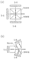
【図2】実施形態1で用いた偏光選択反射板の説明図。
【図3】従来の反射型画像表示装置の模式図。
【図4】ガラスの複屈折(位相差)とコントラスト比の関係を示すグラフ。
【図5】別の色分離・合成システムの説明図。
【図6】実施形態2の投影型カラー画像表示装置の模式図。
【図7】実施形態2の投影型カラー画像表示装置の斜視図。
【図8】(a)および(b)は、実施形態3の投影型カラー画像表示装置の模式図。
【図9】実施形態3の偏光選択反射フィルムの説明図。
【図10】シート状の偏光選択反射板の配置図。
【図11】実施形態4の投影型カラー画像表示装置の模式図。
【図12】従来の投影型画像表示装置の模式図。
【図13】従来の投影型画像表示装置の模式図。
【図14】PBSの原理説明図。
【図15】偏光選択反射フィルムの構成を示す図。
【図16】実施形態5の投影型カラー画像表示装置の模式図。
【符号の説明】
1:メタルハライドランプ
2:放物面鏡
3(a):PBSアレイ
3(b):偏光選択反射フィルム
4:ダイクロイックミラー
5−R、5−G、5−B:反射型液晶パネル
6:投影レンズ
7:スクリーン
8:偏光フィルター
9:偏光フィルター
37:クロスダイクロイックミラー
10、41:クロスダイクロイックプリズム[0001]
BACKGROUND OF THE INVENTION
The present invention relates to a projection type image display apparatus such as a liquid crystal projector, which modulates light from a light source by an image display element and enlarges and projects it onto a screen by a projection lens.
[0002]
[Prior art]
As a projection type image display apparatus having an optical system that performs polarization separation or synthesis on light from a light source, for example, there are those disclosed in Japanese Patent Laid-Open Nos. 63-39294 and 8-160374.
[0003]
First, a projection type display device disclosed in Japanese Patent Laid-Open No. 63-39294 will be described.
[0004]
A schematic configuration diagram of the apparatus is shown in FIG.
[0005]
The light emitted from the
[0006]
Next, a projection type image display device disclosed in JP-A-8-160374 will be described.
[0007]
A schematic configuration diagram of the apparatus is shown in FIG.
[0008]
[0009]
The reflected S-polarized light is separated into red, green, and blue by the
[0010]
[Problems to be solved by the invention]
The projection type image display device as described above has the following drawbacks.
[0011]
The image display element disclosed above uses a regular quadrangular prism-like PBS as a polarization selective reflection element having a function of reflecting or transmitting light according to its polarization direction.
[0012]
Such PBS is usually produced by depositing a dielectric multilayer film on the surface of a glass prism made of optical glass such as BK7 and bonding the two prisms. The glass prism is made, for example, by cooling a glass melted at a high temperature to form a large glass block, cutting out a small glass block therefrom, and further polishing the surface. When the glass is cooled and hardened, the strain is removed by annealing, but it is difficult to completely remove the glass. In addition, this distortion generally occurs nonuniformly in the prism. This distortion causes birefringence with respect to light in the prism. However, since the distortion is not uniform, the degree of birefringence and the direction of the main axis of birefringence exhibit a non-uniform distribution.
[0013]
When light is incident on a uniaxial birefringent material, the traveling speed of light differs between ordinary light and extraordinary light.For example, normal light is incident when obliquely polarized light is incident on the main axis of birefringence. There is a phase difference between the component and the extraordinary light component, which affects the polarization state of the incident light.
[0014]
In the projection type image display element, problems when birefringence remains in PBS will be described using a projection type image display device disclosed in Japanese Patent Laid-Open No. 63-39294.
[0015]
The light emitted from the light source enters the PBS, is separated into two linearly polarized lights whose polarization directions are orthogonal to each other on the film surface, and only the component orthogonal to the incident light whose polarization direction is rotated by a liquid crystal element according to image information. Is ideally transmitted through the PBS and enlarged and projected onto the screen by the projection lens.
[0016]
However, when birefringence remains in the prism constituting the PBS, a component perpendicular to the polarization direction of the incident light is generated while traveling through the glass prism constituting the PBS. The light whose polarization direction is not modulated by the liquid crystal element reaches the screen. That is, even in a black display state, light leaks and the contrast is lowered. The phenomenon described above reduces not only the contrast of the image projected on the screen but also the brightness. In addition, since the distortion in the prism is not uniform, there is a significant problem in performance such as uneven brightness in the image on the screen.
[0017]
Next, problems in the case where PBS having a polarization separation function using a derivative multilayer film is used in a projection type image display apparatus will be described with reference to FIG.
[0018]
A PBS composed of a dielectric multilayer film transmits a component (P-polarized light) having a polarization direction parallel to an incident surface (a surface including incident light and reflected light), and a component (S-polarized light) having a polarization direction perpendicular to the incident surface. It has the property of reflecting. Accordingly, when the incident direction of light is different, the polarization direction of light that is transmitted (P-polarized light) and reflected (S-polarized light) is also different.
[0019]
In a projection type image display apparatus, the illumination light is generally not a perfect parallel light but a light having a certain spread angle. When these illumination lights are incident on the PBS, the incident direction with respect to the film surface of the PBS differs depending on the spread angle of the light. Therefore, the light transmitted and reflected by the PBS is not completely linearly polarized in one direction. Therefore, the use of liquid crystal birefringence as disclosed in JP-A-63-39294 or the like causes a reduction in contrast. In addition, in PBS, the polarization direction of reflected and transmitted light cannot be set to an arbitrary angle. When a display element having a fixed polarization direction of incident light, such as a liquid crystal panel, is used, a wavelength plate or the like is used. , It may be necessary to change the polarization direction of the light from the PBS.
[0020]
These problems also occur in a projection type image display apparatus using a transmission type image display element as disclosed in Japanese Patent Laid-Open No. 8-160374.
[0021]
Further, since the size of PBS usually needs to be about several tens of millimeters according to the size of the liquid crystal panel, those made of glass prism are expensive, leading to an increase in cost and weight of the apparatus.
[0022]
The present invention has been made in order to solve the above-described problems, and an object of the present invention is to provide a low-cost projection-type image display apparatus having an optical system that performs polarization separation or synthesis on light from a light source, and It is lightweight, and it is intended to reduce the decrease in screen illuminance and the decrease in contrast due to birefringence, and suppress the occurrence of uneven brightness.
[0023]
[Means for Solving the Problems]
The projection type image display apparatus of the present invention includes a light source,A polarization selective reflection unit having a function of reflecting or transmitting light from the light source according to a polarization direction; a reflection type image display element that modulates a polarization plane of light from the polarization selective reflection unit according to an image signal; The polarization selective reflection means transmits a linearly polarized light component in one direction regardless of an incident direction of light to the polarized light selective reflection means, and the linearly polarized light in one direction. A polarization selective reflection sheet having an optical transmission axis and a reflection axis for reflecting a linearly polarized light component orthogonal to the component, and a first polarizing filter means for transmitting only the linearly polarized light component in one direction of the light, the reflective image display Laminated in order from the side close to the element, provided on the glass substrate, and disposed such that the polarization direction of the light incident on the pixel display element coincides with the transmission axis or the reflection axis. Said bias The optical path between the selective reflection means is further provided with a second polarizing filter means having a transmission axis arranged so as to be in a crossed Nicol state with respect to the transmission axis of the first polarizing filter means. .
[0024]
MaThe projection type image display apparatus of the present invention includes a light source, color separation means for separating light from the light source into a plurality of lights having different wavelength ranges, and the plurality of lights separated by the color separation means, respectively. A plurality of polarization selective reflection means for reflecting or transmitting according to the polarization direction, a plurality of reflective image display elements for modulating the polarization planes of the respective lights from the respective polarization selective reflection means in accordance with an image signal, A combining unit configured to combine the light beams reflected by the reflection type image display element; and a projection lens configured to project the light combined by the combining unit onto a screen. Are provided between the light source and each polarization selective reflection means so as to form an optical path of each light in a predetermined wavelength range, respectively, and the color synthesizing means includes the each polarization selective reflection means and the above Between the projection lens Each of the polarization selective reflection means arranged in the optical path transmits a linear polarization component in one direction regardless of the incident direction of the light to each polarization selective reflection means, and the linear polarization component in one direction. A reflection-selective reflection sheet having an optical transmission axis and a reflection axis for reflecting a linearly polarized light component orthogonal to the first polarization filter means for transmitting only a linearly polarized light component in one direction of light, and the reflective image display element Are provided in order on the glass substrate, and the polarization direction of the light incident on each reflective image display element coincides with the transmission axis or the reflection axis of each polarization selective reflection sheet. It is characterized by being arranged respectively.
[0025]
Each transmission axis of each light separated by the color separation means is arranged in a crossed Nicols state with respect to the transmission axis of each first polarization filter means in each optical path to each polarization selective reflection means. It is preferable that a second polarizing filter means is further provided.
[0028]
The operation of the present invention will be described below.
[0029]
Glass having birefringence in the optical path from the polarization selective reflection means to the image display element and in the optical path from the image display element to the polarization selective reflection means by using a plate-shaped or sheet-like one as the polarization selective reflection means The amount of can be greatly reduced. For this reason, the fall of the contrast on the screen by the influence of the birefringence of glass and the fall of illumination intensity can be improved. In addition, since a large glass prism is not used, the cost is low and the weight of the apparatus can be reduced.
[0030]
In addition, since the polarization selective reflection means has a transmission axis and a reflection axis that transmit a linearly polarized light component that is unique within the plane and reflects the linearly polarized light component orthogonal thereto, even if the illumination light has a spread angle, The light transmitted and reflected by the polarization selective reflection means is linearly polarized light in one direction. As a result, contrast can be improved. Further, by adjusting the transmission axis and the reflection axis, it is possible to reflect or transmit light having an arbitrary polarization direction. Therefore, even if the polarization direction of light to be incident on the liquid crystal panel is inclined with respect to the P-polarized light and the S-polarized light, it is not necessary to change the polarization by the waveplate, so that the cost is low and the light passes through the waveplate. It is possible to prevent the loss of light during the process.
[0031]
When a PBS array in which a plurality of small PBSs are arranged in a plate shape is used as the polarization selective reflection means, the optical path through which light passes through the glass is shortened. For this reason, the influence by the birefringence of the glass which forms PBS can be reduced.
[0032]
When the polarization filter means is provided between the light source and the polarization selective reflection means, the polarization direction of the light incident on the polarization selective reflection means can be limited to only one direction. Regardless of the extinction ratio, only light in one polarization direction can be guided to the image display element. Further, when a polarization filter means is provided between the polarization selective reflection means and the projection lens, only light in one polarization direction is guided to the screen regardless of the polarization characteristics (extinction ratio) of the polarization selective reflection means. Is possible. As a result, an apparatus with higher contrast can be realized by these effects.
[0033]
When a polarizing filter means disposed between the polarized light selective reflecting means and the projection lens is provided, the polarizing filter means and the polarized light selective reflecting means are stacked, and the polarized light selective reflecting means is directed to the reflective image display element side. Thus, a device with higher contrast can be realized. This is because there is no element having birefringence in the optical path between the polarization selective reflection means and the polarizing filter.
[0034]
In addition, when no means for separating or synthesizing light is disposed in the optical path between the polarization selective reflection means and the reflective image display element, birefringence is applied to the optical component used as the light separating and synthesizing means. Even if there is, it is possible to suppress the decrease in contrast and the occurrence of uneven brightness.
[0035]
DETAILED DESCRIPTION OF THE INVENTION
(Embodiment 1)
FIG. 1 is a schematic view of a projection type color image display apparatus of the present invention. In this embodiment, a metal halide lamp having a power of 250 W and an arc length of 3 mm is used as the
[0036]
The light reflected by the panel is synthesized again by the dichroic mirrors 4-R and 4-B, and the polarized light is rotated by the reflective liquid crystal display panel, and only the light that becomes the P-polarized light component passes through the PBS array 3 (a). Then, the light is projected onto the
[0037]
In the present embodiment, the
[0038]
Here, a comparative example is shown in order to explain the effect of this embodiment. In this comparative example, the polarization
[0039]
In the comparative example, in order to cover the display area of the 1.3-inch panel, a PBS having a width of about 40 mm or more is required in consideration of the light spread angle. Further, when used in a reflective optical system as in the present embodiment, the light travels back and forth through the PBS, and thus passes through twice as much glass as 80 mm. FIG. 4 shows the relationship between the birefringence (phase difference) of glass and the contrast ratio. Usually, birefringence in glass is 2 to 5 nm / cm even if it has a good quality. Therefore, according to FIG. 4, when this PBS is used, a phase difference of about 16 to 40 nm exists. For this reason, it can be seen that in an apparatus using one PBS, the contrast is extremely lowered.
[0040]
On the other hand, the size of each PBS constituting the polarization
[0041]
When the configuration shown in FIG. 3 was used, a place where the contrast ratio was less than 50: 1 occurred in the screen. On the other hand, as described in the present embodiment, when the projection is configured using the PBS array 3 (a), there is no unevenness in contrast while maintaining the brightness (contrast ratio of 100: 1 or more over the entire screen), and A lightweight and inexpensive image display device could be realized.
[0042]
In this embodiment, the R reflection and B reflection dichroic mirrors are used as the color separation / combination means, but any one having a color separation / combination function may be used, as shown in FIGS. 5 (a) and 5 (b). It is also possible to use a so-called Phillips type prism composed of three dichroic prisms or three prisms.
[0043]
However, in this case, as described above, since the contrast is lowered due to the birefringence in these prisms, it is disclosed in Japanese Patent Laid-Open Nos. 5-341254 and 8-21357. It is preferable to use a prism in which the inside of the prism is filled with a liquid to reduce birefringence.
[0044]
(Embodiment 2)
FIG. 6 is a schematic diagram of a projection type color image display apparatus according to the second embodiment of the present invention. In this embodiment, the same optical components as those in
[0045]
After the light from the
[0046]
In the present embodiment, a
[0047]
In the first embodiment, the unevenness in contrast can be reduced to a practical level or more, but white light is separated into RGB light and combined between the PBS array 3 (a) and the reflective liquid
[0048]
In other words, the color separation / combination system using these prisms has a large polarization dependency of its spectral characteristics, so that when light having a different incident direction (illumination light having a spread angle) is incident as in the case of PBS, Even if the incident light has only one direction of linearly polarized light, the transmitted and reflected light is not unidirectional linearly polarized light but has light of a component orthogonal thereto. In addition, when a glass prism is used, birefringence occurs, which causes the contrast to decrease.
[0049]
On the other hand, in this configuration, before entering the PBS array 3 (a), the light is divided into RGB lights and synthesized by the cross dichroic prism after exiting the PBS array 3 (a). That is, an optical component that performs color separation and synthesis that affects the contrast ratio is disposed outside the PBS array 3 (a) and the reflective liquid
[0050]
When the projection is configured as described above, it is possible to realize an image display device having a contrast ratio of 200: 1 or more over the entire screen while maintaining the same brightness as in the first embodiment even when a glass prism is used. It was.
[0051]
In this embodiment, a dichroic mirror is used for color separation and a cross dichroic prism is used for color composition. In addition, a cross dichroic prism may be used for color separation, a dichroic mirror may be used for color composition, and a Philips type prism as shown in FIG. 5B. FIG. 7 shows an example of a projection type color image display device that performs color separation using a cross
[0052]
In the configuration shown in FIG. 7, light from the light source is reflected by the
[0053]
In the configuration shown in FIG. 7, all three optical paths between the light source and the reflective liquid crystal panels 5-R, 5-G, 5-B corresponding to the R, G, and B lights are the same. . For this reason, the white balance is not lost and a good image is obtained.
[0054]
The same effect can be obtained even if the cross
[0055]
(Embodiment 3)
FIGS. 8A and 8B are schematic views of a projection color image display apparatus according to the third embodiment of the present invention.
[0056]
In this embodiment, instead of the PBS array 3 (a) used as the polarization
[0057]
As the polarization selective reflection film 3 (b), for example, a
[0058]
Since this polarization selective reflection film 3 (b) itself has a transmission axis and a reflection axis, as shown in FIG. The linearly polarized light is parallel to each of the transmission axis and the reflection axis in (b). In addition, the polarization selective reflection film 3 (b) is not affected by birefringence because the film thickness is very thin. Therefore, as described above, the contrast can be further improved as compared with the case where the PBS in which the polarization direction of the reflected and transmitted light is different depending on the incident direction (divergence angle) of the light is used.
[0059]
In the apparatus shown in FIGS. 8A and 8B, the polarization direction of the incident light with respect to the reflective
[0060]
When a projection was configured with the configuration of FIG. 8A, a contrast ratio of 200: 1 or more could be realized over the entire screen while maintaining the same brightness as in the first and second embodiments. Similarly, with the configuration of FIG. 8B, a contrast ratio of 300: 1 or more could be realized.
[0061]
In the present embodiment, the reflection axis of the polarization selective reflection film 3 (b) is arranged so as to be perpendicular to the paper surface, but the direction of the axis is not limited to this. The direction of the reflection axis may be any direction such as a horizontal direction or a 45 ° direction in accordance with the characteristics of the liquid crystal panel.
[0062]
In the first, second, and third embodiments, the plate-like PBS array 3 (a) and the polarization-selective reflection film 3 (b) in which a plurality of small PBSs are arranged are used as the polarization
[0063]
The contrast in the first, second, and third embodiments is determined by the optical path between the polarizing plates arranged before and after the polarization
[0064]
In order to give strength to the sheet-like polarization
[0065]
Further, when the sheet-like polarization
[0066]
(Embodiment 4)
FIG. 11 is a schematic diagram of a projection type color image display apparatus according to the fourth embodiment of the present invention.
[0067]
In the apparatus of FIG. 11, the light emitted from the
[0068]
In this embodiment, the
[0069]
In the structure described in the fourth embodiment, unlike the structure described in the third embodiment, the lengths of the three optical paths from the light source to the projection lens through which light of each color of R, G, B passes are the same. For this reason, the white balance of the image does not shift. Therefore, it is not necessary to use a relay lens that has been conventionally required to prevent a white balance shift, and the apparatus can be reduced in size and cost.
[0070]
When the projection is configured as described above, it is possible to realize an image display device having a contrast ratio of 300: 1 or more over the entire screen while maintaining the same brightness as that of the first embodiment even when a glass prism is used. It was.
[0071]
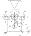
(Embodiment 5)
A projection type color image display apparatus according to
[0072]
In the apparatus shown in FIG. 16, two polarization selective reflection films 3 (b) 1 and 3 (b) 2 are used. In addition, transmissive
[0073]
The light from the
[0074]
The light reflected by the polarization selective reflection film 3 (b) 1 enters the dichroic mirror 4-B that reflects blue light. The reflected blue light is reflected by the
[0075]
On the other hand, red and green light are transmitted through the dichroic mirror 4-B and are incident on the dichroic mirror 4-R that reflects red light. The reflected red light is incident on the red
[0076]
Each of the
[0077]
The light of each color transmitted through the
[0078]
Thereafter, the combined RGB light is incident on another polarization selective reflection film 3 (b) 2. Of the incident linearly polarized light, only the linearly polarized light whose plane of polarization is rotated by 90 ° by the
[0079]
On the other hand, the linearly polarized light transmitted through the polarization selective reflection film 3 (b) 1 is reflected by the two total reflection mirrors 36 and then enters the
[0080]
Since the polarization selective reflection films 3 (b) 1 and 3 (b) 2 have a transmission axis and a reflection axis in the plane of the film that transmit a specific linearly polarized light component and reflect a linearly polarized light component orthogonal thereto, Even if the illumination light has a divergence angle, the light transmitted and reflected by the polarization selective reflection film is linearly polarized light having a polarization plane in one direction. For this reason, the contrast of the displayed image is improved.
[0081]
Moreover, since the directions of the transmission axis and the reflection axis of the polarization selective reflection films 3 (b) 1 and 3 (b) 2 can be arbitrarily set, the directions of the polarization vectors of the transmitted light and the reflected light can be controlled. For this reason, the polarization direction of the incident light is adjusted to the preferred polarization direction of the light with respect to the
[0082]
【The invention's effect】
As described above, according to the present invention, contrast unevenness can be eliminated by using a plate-like or sheet-like polarization selective reflection element with low birefringence in the projection type image display device. A uniform image can be realized.
[0083]
In addition, illumination is provided by including a polarization selective reflection element having an optical transmission axis and a reflection axis that transmits a linearly polarized light component in one direction regardless of the incident angle of light and reflects light of a component orthogonal thereto. Even if the light has a spread angle, the transmitted light and the reflected light are linearly polarized light parallel to the transmission axis and the reflection axis, so that the contrast can be further improved.
[0084]
Further, by performing color separation / combination in an optical path other than between the polarization separation element and the reflective liquid crystal display element, it is possible to eliminate a decrease in contrast due to the color separation / synthesis optical system.
[0085]
Furthermore, when the sheet-like polarization selective reflection plate is used by bonding to a transparent substrate such as glass, the light passes through the polarization plate by sandwiching the polarization plate between the polarization selective reflection plate and the glass, Since it passes through the transparent substrate, the influence of the birefringence of the transparent substrate can be completely prevented. For this reason, contrast can be further improved.
[Brief description of the drawings]
FIG. 1 is a schematic diagram of a projection color image display apparatus according to a first embodiment of the present invention.
FIG. 2 is an explanatory diagram of a polarization selective reflection plate used in the first embodiment.
FIG. 3 is a schematic diagram of a conventional reflective image display device.
FIG. 4 is a graph showing the relationship between birefringence (phase difference) and contrast ratio of glass.
FIG. 5 is an explanatory diagram of another color separation / synthesis system.
FIG. 6 is a schematic diagram of a projection color image display apparatus according to a second embodiment.
FIG. 7 is a perspective view of a projection color image display apparatus according to a second embodiment.
8A and 8B are schematic views of a projection type color image display apparatus according to a third embodiment.
FIG. 9 is an explanatory view of a polarization selective reflection film of
FIG. 10 is a layout view of a sheet-like polarization selective reflection plate.
FIG. 11 is a schematic diagram of a projection color image display apparatus according to a fourth embodiment.
FIG. 12 is a schematic diagram of a conventional projection type image display apparatus.
FIG. 13 is a schematic diagram of a conventional projection type image display apparatus.
FIG. 14 is a diagram illustrating the principle of PBS.
FIG. 15 is a diagram showing a configuration of a polarization selective reflection film.
FIG. 16 is a schematic diagram of a projection color image display apparatus according to a fifth embodiment.
[Explanation of symbols]
1: Metal halide lamp
2: Parabolic mirror
3 (a): PBS array
3 (b): Polarization selective reflection film
4: Dichroic mirror
5-R, 5-G, 5-B: reflective liquid crystal panel
6: Projection lens
7: Screen
8: Polarizing filter
9: Polarizing filter
37: Cross dichroic mirror
10, 41: Cross dichroic prism
Claims (3)
該光源からの光を偏光方向に応じて反射または透過する機能を有する偏光選択反射手段と、
該偏光選択反射手段からの光の偏波面を画像信号に合わせて変調する反射型画像表示素子と、を備えた投影型画像表示装置であって、
該偏光選択反射手段は、該偏光選択反射手段への光の入射方向に関わらず、一方向の直線偏光成分を透過し、該一方向の直線偏光成分に直交する直線偏光成分を反射する光学的な透過軸及び反射軸を有する偏光選択反射シートと、光の一方向の直線偏光成分だけ透過させる第1偏光フィルタ手段とが、前記反射型画像表示素子に近い側より順に積層されて、ガラス基板上に設けられるとともに、前記画素表示素子に入射する光の偏光方向が、該透過軸または反射軸に一致するように配置されており、
前記光源と前記偏光選択反射手段の間の光路に、前記第1偏光フィルタ手段の透過軸に対してクロスニコル状態になるように透過軸が配置された第2偏光フィルタ手段がさらに設けられていることを特徴とする投影型画像表示装置。A light source;
Polarization selective reflection means having a function of reflecting or transmitting light from the light source according to the polarization direction;
A projection-type image display device comprising: a reflection-type image display element that modulates a polarization plane of light from the polarization selective reflection means according to an image signal ,
The polarization selective reflection means, regardless of the incident direction of the light to the polarizing selective reflecting means, passes through the one-way linear polarization component, an optical reflecting a linearly polarized light component perpendicular to the linearly polarized light component of the one-way A polarizing selective reflection sheet having a transparent transmission axis and a reflection axis, and first polarizing filter means for transmitting only a linearly polarized light component in one direction of light are laminated in order from the side closer to the reflective image display element, and a glass substrate. And is arranged so that the polarization direction of light incident on the pixel display element coincides with the transmission axis or the reflection axis ,
In the optical path between the light source and the polarization selective reflection means, there is further provided a second polarization filter means having a transmission axis arranged so as to be in a crossed Nicols state with respect to the transmission axis of the first polarization filter means. A projection-type image display device characterized by that.
該光源からの光を波長域の異なる複数の光に分離する色分離手段と、
該色分離手段で分離された前記複数の光をそれぞれ偏光方向に応じて反射または透過する複数の偏光選択反射手段と、
前記各偏光選択反射手段からのそれぞれの光の偏波面を画像信号に合わせて変調する複数の反射型画像表示素子と、
前記各反射型画像表示素子で反射された前記各光を合成する合成手段と、
該合成手段によって合成された光をスクリーンに投影する投影レンズとを備え、
前記色分離手段が、前記各偏光選択反射手段に対して所定の波長域の前記各光の光路をそれぞれ形成するように、前記光源と前記各偏光選択反射手段との間に設けられ、
前記色合成手段が、前記各偏光選択反射手段と前記投影レンズとの間の光路に配置され、
前記各偏光選択反射手段のそれぞれが、前記各偏光選択反射手段への光のそれぞれの入射方向に関わらず、一方向の直線偏光成分を透過し、該一方向の直線偏光成分に直交する直線偏光成分を反射する光学的な透過軸および反射軸を有する偏光選択反射シートと、光の一方向の直線偏光成分だけ透過させる第1偏光フィルタ手段とが、前記反射型画像表示素子に近い側より順に積層されて、ガラス基板上に設けられるとともに、前記各反射型画像表示素子にそれぞれ入射する光の偏光方向が、前記各偏光選択反射シートの前記透過軸または反射軸に一致するようにそれぞれ配置されていることを特徴とする投影型画像表示装置。A light source;
Color separation means for separating light from the light source into a plurality of lights having different wavelength ranges;
A plurality of polarization selective reflection means for reflecting or transmitting in accordance with the separated plurality of light into respective polarization directions in the color separation means,
A plurality of reflective image display elements that modulate the polarization plane of each light from each of the polarization selective reflection means in accordance with an image signal ;
And combining means for combining said respective light reflected by the reflection type image display device,
A projection lens that projects the light combined by the combining means onto a screen ,
The color separation means is provided between the light source and each polarization selective reflection means so as to form an optical path of each light in a predetermined wavelength range with respect to each polarization selective reflection means ,
The color synthesizing means, wherein arranged in the optical path between the projection lens and the polarized-light selective reflection means,
Wherein each of the polarized-light selective reflection means, wherein regardless of the respective direction of incidence of light to the polarizing selective reflecting means, passes through the one-way linear polarization component, the linearly polarized light orthogonal to the linearly polarized light component of the one-way A polarizing selective reflection sheet having an optical transmission axis and a reflection axis for reflecting the components, and a first polarizing filter means for transmitting only the linearly polarized light component in one direction of light, in order from the side closer to the reflective image display element are stacked, together provided on a glass substrate, the polarization direction of light incident respectively to the each reflection type image display element, it is arranged so as to coincide the said transmission axis or the reflection axis of the polarization selective reflection sheet A projection-type image display device.
Priority Applications (1)
| Application Number | Priority Date | Filing Date | Title |
|---|---|---|---|
| JP2002191458A JP3659637B2 (en) | 2002-06-28 | 2002-06-28 | Projection-type image display device |
Applications Claiming Priority (1)
| Application Number | Priority Date | Filing Date | Title |
|---|---|---|---|
| JP2002191458A JP3659637B2 (en) | 2002-06-28 | 2002-06-28 | Projection-type image display device |
Related Parent Applications (1)
| Application Number | Title | Priority Date | Filing Date |
|---|---|---|---|
| JP18048697A Division JP3444521B2 (en) | 1997-06-20 | 1997-06-20 | Projection type image display device |
Publications (2)
| Publication Number | Publication Date |
|---|---|
| JP2003121793A JP2003121793A (en) | 2003-04-23 |
| JP3659637B2 true JP3659637B2 (en) | 2005-06-15 |
Family
ID=19195506
Family Applications (1)
| Application Number | Title | Priority Date | Filing Date |
|---|---|---|---|
| JP2002191458A Expired - Lifetime JP3659637B2 (en) | 2002-06-28 | 2002-06-28 | Projection-type image display device |
Country Status (1)
| Country | Link |
|---|---|
| JP (1) | JP3659637B2 (en) |
Cited By (1)
| Publication number | Priority date | Publication date | Assignee | Title |
|---|---|---|---|---|
| CN103207509A (en) * | 2012-01-12 | 2013-07-17 | 三菱电机株式会社 | Light Source Device And Projecting Display Device |
Families Citing this family (2)
| Publication number | Priority date | Publication date | Assignee | Title |
|---|---|---|---|---|
| WO2017003719A2 (en) * | 2015-06-30 | 2017-01-05 | 3M Innovative Properties Company | Illuminator |
| RU2736919C1 (en) * | 2020-05-25 | 2020-11-23 | Самсунг Электроникс Ко., Лтд. | System for projecting a virtual image onto a screen with the effect of eliminating the effect of solar radiation |
-
2002
- 2002-06-28 JP JP2002191458A patent/JP3659637B2/en not_active Expired - Lifetime
Cited By (3)
| Publication number | Priority date | Publication date | Assignee | Title |
|---|---|---|---|---|
| CN103207509A (en) * | 2012-01-12 | 2013-07-17 | 三菱电机株式会社 | Light Source Device And Projecting Display Device |
| CN103207509B (en) * | 2012-01-12 | 2015-06-24 | 三菱电机株式会社 | Light Source Device And Projecting Display Device |
| US9310033B2 (en) | 2012-01-12 | 2016-04-12 | Mitsubishi Electric Corporation | Light source device and projection-type display apparatus |
Also Published As
| Publication number | Publication date |
|---|---|
| JP2003121793A (en) | 2003-04-23 |
Similar Documents
| Publication | Publication Date | Title |
|---|---|---|
| JP3444521B2 (en) | Projection type image display device | |
| US6398364B1 (en) | Off-axis image projection display system | |
| US20060285042A1 (en) | Contrast Enhancement for Liquid Crystal Based Projection Systems | |
| US20050213043A1 (en) | Optical unit and projection-type image display apparatus using the same | |
| JPH06138413A (en) | Plate type polarized light separating device and polarized light illuminating device using the same | |
| JPH03122631A (en) | Projection type liquid crystal display device | |
| WO2006020359A2 (en) | Projection display system using multiple light sources and polarizing element for using with same | |
| JP2002544567A (en) | Color imaging system and method | |
| CN103890639A (en) | Tilted dichroic polarizing beamsplitter | |
| JP3417757B2 (en) | Liquid crystal display device and light beam separating method thereof | |
| US20080094576A1 (en) | Projection system incorporating color correcting element | |
| JP2010204333A (en) | Projector | |
| US5164821A (en) | Image projection system | |
| JPH11142838A (en) | Color shutter using reflection type polarizer | |
| JP2003270636A (en) | Liquid crystal panel, liquid crystal device, and projector using liquid crystal device | |
| JP5228559B2 (en) | Image display device and optical compensation device | |
| JP3385915B2 (en) | Projection image display | |
| JP3554520B2 (en) | Image display device | |
| JP7205536B2 (en) | Image display device and image display unit | |
| JP3659637B2 (en) | Projection-type image display device | |
| JP3654798B2 (en) | Image display device and lighting device | |
| JP3491809B2 (en) | Projection type image display device | |
| JP3723409B2 (en) | Wavelength selection element and display device using the same | |
| JP2000171770A (en) | Projection type display device | |
| JP3452843B2 (en) | Image display device |
Legal Events
| Date | Code | Title | Description |
|---|---|---|---|
| A131 | Notification of reasons for refusal |
Free format text: JAPANESE INTERMEDIATE CODE: A131 Effective date: 20041222 |
|
| A521 | Written amendment |
Free format text: JAPANESE INTERMEDIATE CODE: A523 Effective date: 20050221 |
|
| TRDD | Decision of grant or rejection written | ||
| A01 | Written decision to grant a patent or to grant a registration (utility model) |
Free format text: JAPANESE INTERMEDIATE CODE: A01 Effective date: 20050314 |
|
| A61 | First payment of annual fees (during grant procedure) |
Free format text: JAPANESE INTERMEDIATE CODE: A61 Effective date: 20050314 |
|
| R150 | Certificate of patent or registration of utility model |
Free format text: JAPANESE INTERMEDIATE CODE: R150 |
|
| FPAY | Renewal fee payment (event date is renewal date of database) |
Free format text: PAYMENT UNTIL: 20080325 Year of fee payment: 3 |
|
| FPAY | Renewal fee payment (event date is renewal date of database) |
Free format text: PAYMENT UNTIL: 20090325 Year of fee payment: 4 |
|
| FPAY | Renewal fee payment (event date is renewal date of database) |
Free format text: PAYMENT UNTIL: 20100325 Year of fee payment: 5 |
|
| FPAY | Renewal fee payment (event date is renewal date of database) |
Free format text: PAYMENT UNTIL: 20100325 Year of fee payment: 5 |
|
| FPAY | Renewal fee payment (event date is renewal date of database) |
Free format text: PAYMENT UNTIL: 20110325 Year of fee payment: 6 |
|
| FPAY | Renewal fee payment (event date is renewal date of database) |
Free format text: PAYMENT UNTIL: 20120325 Year of fee payment: 7 |
|
| FPAY | Renewal fee payment (event date is renewal date of database) |
Free format text: PAYMENT UNTIL: 20120325 Year of fee payment: 7 |
|
| FPAY | Renewal fee payment (event date is renewal date of database) |
Free format text: PAYMENT UNTIL: 20130325 Year of fee payment: 8 |