JP3659623B2 - Tankless toilet - Google Patents
Tankless toilet Download PDFInfo
- Publication number
- JP3659623B2 JP3659623B2 JP2000002384A JP2000002384A JP3659623B2 JP 3659623 B2 JP3659623 B2 JP 3659623B2 JP 2000002384 A JP2000002384 A JP 2000002384A JP 2000002384 A JP2000002384 A JP 2000002384A JP 3659623 B2 JP3659623 B2 JP 3659623B2
- Authority
- JP
- Japan
- Prior art keywords
- toilet
- base plate
- cleaning
- cleaning mechanism
- tankless
- Prior art date
- Legal status (The legal status is an assumption and is not a legal conclusion. Google has not performed a legal analysis and makes no representation as to the accuracy of the status listed.)
- Expired - Fee Related
Links
Images


Description
【0001】
【発明の属する技術分野】
本発明は、洗浄タンクを有さず、水道管等の給水管から供給される洗浄水を便器本体に直接供給してその便器本体を洗浄可能なタンクレス便器に関する。
【0002】
【従来の技術】
一般的な水洗式便器では、水道管等の給水管から供給される洗浄水をロータンク等の洗浄タンクに一旦貯留し、その洗浄タンクに貯留した洗浄水により便器本体の洗浄を行う。しかし、かかる一般的な水洗式便器では、洗浄タンクの設置スペースが必要とされる。
【0003】
このため、近年、スペースの有効活用等の観点から、洗浄タンクを廃止し、水道管等の給水管から供給される洗浄水を便器本体に直接供給し、便器本体をその洗浄水により洗浄可能な便器洗浄機構を有する便器洗浄装置を便器本体に一体に備えたタンクレス便器が開発されつつある(特開平3−253630号公報)。
【0004】
【発明が解決しようとする課題】
しかし、上記従来のタンクレス便器は、便器本体に便器洗浄装置が取り付けられているだけであり、人体の局部を洗浄可能な局部洗浄機構を有する便座・便蓋装置が取り付けられてはいない。このため、このタンクレス便器では、用便等後の局部を洗浄したいという使用者の要望に答えられない。
【0005】
仮にかかるタンクレス便器に局部洗浄機構を設ける場合、便器本体に便器洗浄機構を固定するベースプレートにその局部洗浄機構を併せて固定するのであれば、そのベースプレートが大型化し、ひいてはタンクレス便器も大型化して設置スペースに苦慮する自体も招来してしまう。局部洗浄機構を固定した他のベースプレートをその便器本体に固定し、便器本体に別途そのスペースを確保する場合も同様である。
【0006】
本発明は、上記従来の実情に鑑みてなされたものであって、小型化により設置スペースの確保が容易であるとともに、用便等後の局部を洗浄したいという使用者の要望に答え得るタンクレス便器を提供することを解決すべき課題とする。
【0007】
【課題を解決するための手段】
本発明のタンクレス便器は、便器本体と、該便器本体に取り付けられ、洗浄タンクを有さず、該便器本体を洗浄水により洗浄可能な便器洗浄機構を有する便器洗浄装置を備えたタンクレス便器において、
人体の局部を洗浄可能な局部洗浄機構を有する便座・便蓋装置を前記便器本体に取り付ける場合、該便座・便蓋装置として前記局部洗浄機構が固定された便座ベースプレートを有するものが採用されるとともに、前記便器洗浄装置として前記便器洗浄機構が固定された便器洗浄ベースプレートを有するものが採用され、該便座ベースプレートが該便器本体に形成された便座取付け穴により該便器本体に取り付けられ、該便器洗浄ベースプレートは、該局部洗浄機構と該便器洗浄機構との干渉を回避しつつ、該便座ベースプレートと該便器本体との間に挟持されることを特徴とする。
【0008】
本発明のタンクレス便器では、便座・便蓋装置の便座ベースプレートが便器本体に形成された便座取付け穴により便器本体に取り付けられ、便器洗浄装置の便器洗浄ベースプレートはその便座ベースプレートと便器本体との間に挟持される。この際、便座・便蓋装置の局部洗浄機構と便器洗浄装置の便器洗浄機構との干渉は回避されている。こうして、このタンクレス便器では、便座・便蓋装置の局部洗浄機構が便器本体に取り付けられ、用便等後の局部を洗浄したいという使用者の要望に答え得る。また、このタンクレス便器では、こうして局部洗浄機構を設ける場合でも、便座ベースプレートと便器洗浄ベースプレートとが一部で重ね合わされているため、小型化している。
【0009】
したがって、本発明のタンクレス便器では、小型化により設置スペースの確保が容易であるとともに、用便等後の局部を洗浄したいという使用者の要望に答えることができる。
【0010】
便座取付け穴は汎用の便座・便蓋装置を取り付け可能であることが好ましい。こうであれば、トイレ室への設置を検討しているタンクレス便器の購入者は、その購入の際、予算の都合等により当初は汎用の便座・便蓋装置を取り付けていた場合でも、便器本体その他の機器を交換する必要なく、局部洗浄機構を有する便座・便蓋装置に交換することができる。この逆も可能である。こうして、購入者の自由な選択を確保できる。また、こうであれば、便器本体を共通化することができるため、高い量産化により製造コストの低廉化を実現できる。このような便座取付け穴は、例えば日本では間隔が140mmとJIS規格により定められており、その他米国等、他国の規格で定められる。
【0011】
便座ベースプレートは、便器洗浄機構から漏れる水を便器本体内に案内する案内路をもつことができる。
【0012】
また、便座・便蓋装置が局部洗浄機構を隠蔽するカバーを有する場合、便器洗浄装置の便器洗浄機構がこのカバーにより隠蔽されるように構成することもできる。
【0013】
【発明の実施の形態】
以下、本発明を具体化した実施形態について図面を参照しつつ説明する。
【0014】
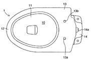
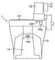
本実施形態に係るタンクレス便器は洗浄タンクを有さない水洗式便器であり、図1及び図2に示す陶器製の便器本体1を備えている。この便器本体1は、排泄物を受けるボウル部10をもつ便鉢11と、便鉢部11の前部側の上縁回りに形成され、内部に図示しないリム通水路をもつリム12と、便鉢11の後部側に広面積の平坦な水平面で形成された取付面13とを備えている。ボウル部10の底には図示しないジェットノズル取付孔が形成されている。取付面13には、図1に示すように、2個1組の便座取付け穴13a、13bが上下方向に貫設されている。これら便座取付け穴13a、13bの間隔は140mmである。また、図2に示すように、取付面13の後壁にはリム通水路に連通するリム開口13cが形成されている。ジェットノズル取付孔には図示しないジェットノズルが取り付けられている。また、便鉢11の後部には上端にジェット開口14aをもつ後部台座14が一体に設けられている。
【0015】
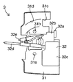
また、図3及び図4に示すように、便器洗浄装置2では便器洗浄ベースプレート21に便器洗浄機構22が固定されている。便器洗浄ベースプレート21には便座取付け穴13a、13bと整合する取付け穴21a、21bが上下方向に貫設されている。また、便器洗浄機構22は、給水口22aを有しつつストレーナを内蔵する逆止弁22bと、この逆止弁22bと連通するリム用及びジェット用の開閉弁22cと、この開閉弁22cの上方に設けられて開閉弁22cを開閉するカム装置22dと、このカム装置22dの側方に設けられてカム装置22dを駆動するモータ装置22eと、このモータ装置22eよりさらに側方に突出し、手動によりカム装置22dを駆動可能な手動ハンドル22fとを有している。便器洗浄ベースプレート21は開閉弁22cの下端を剥き出しにする切欠21cを有しており、開閉弁22cの後方下端には、便器本体1のリム開口13cに接続されるリム給水口22gが切欠21cより大きく下方に延在しているとともに、ジェットノズルに接続されるジェット給水口22hが切欠21cより小さく下方に延在している。一方、開閉弁22cの前方上端にはリム給水口22g及びジェット給水口22hと連通するバキュームブレーカ23が固定されている。
【0016】
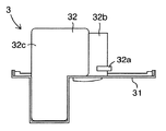
さらに、図5及び図6に示すように、便座・便蓋装置であるシャワートイレ3では便座ベースプレート31に人体の局部を洗浄可能な局部洗浄機構32が固定されている。便座ベースプレート31には便座取付け穴13a、13b及び取付け穴21a、21bと整合する取付け穴31a、31bが上下方向に貫設されている。また、便座ベースプレート31には、バキュームブレーカ23を剥き出しにする切欠31cを有しており、切欠31cから前方に向けてバキュームブレーカ23から漏れる水を便器本体1の便鉢11内に案内する案内路31dが凹設されている。一方、局部洗浄機構32は、給水口32aを有する本体32bと、本体32bに接続された温水タンク32cと、本体32bから前方に延出可能なお尻用ノズル32d及びビデ用ノズル32eとを有している。
【0017】
このタンクレス便器は以下のように組み付けられる。まず、図7及び図8に示すように、便器洗浄装置2の便器洗浄ベースプレート21の取付け穴21a、21bを便器本体1の便座取付け穴13a、13bと整合させた状態とする。この状態において、図9及び図10に示すように、シャワートイレ3の便座ベースプレート31の取付け穴31a、31bに図示しないボルトを挿入し、便器洗浄ベースプレート21の取付け穴21a、21bを介して便器本体1の便座取付け穴13a、13bを通過させ、裏面よりそれらボルトを図示しないナットで螺合する。こうして、便器洗浄装置2の便器洗浄ベースプレート21はその便座ベースプレート31と便器本体1との間に挟持される。また、局部洗浄機構32における本体32bは給水口32aにより開閉弁22cに接続される。この際、シャワートイレ3の局部洗浄機構32と便器洗浄装置2の便器洗浄機構22との干渉は回避されている。
【0018】
そして、バキュームブレーカ23には案内路31dに向かってゴムホース24が嵌められる。また、便器本体1のリム開口13cにリム給水口22gを接続するとともに、ジェット給水口22hとジェットノズルとをジェット用導水管により接続する。この後、図11に示すように、シャワートイレ3の残部である便座33及び便蓋34が便座ベースプレート31に揺動可能に支承されるとともに、同様にシャワートイレ3の残部であるカバー35が便座ベースプレート31に取り付けられる。こうして、カバー35内に局部洗浄機構32が隠蔽される。便器洗浄機構22の給水口22aには可撓性をもつフレキシブルホース40が接続され、フレキシブルホース40は図示しない止水栓を介して水道管等の給水管に接続される。
【0019】
こうして、このタンクレス便器では、シャワートイレ3の局部洗浄機構32が便器本体1に取り付けられ、用便等後の局部を洗浄したいという使用者の要望に答え得る。また、このタンクレス便器では、こうして局部洗浄機構32を設ける場合でも、便座ベースプレート31と便器洗浄ベースプレート21とが一部で重ね合わされているため、小型化している。
【0020】
したがって、このタンクレス便器では、小型化により設置スペースの確保が容易であるとともに、用便等後の局部を洗浄したいという使用者の要望に答えることができる。
【図面の簡単な説明】
【図1】実施形態に係り、タンクレス便器の便器本体の平面図である。
【図2】実施形態に係り、タンクレス便器の便器本体の背面図である。
【図3】実施形態に係り、タンクレス便器の便器洗浄装置の平面図である。
【図4】実施形態に係り、タンクレス便器の便器洗浄装置の背面図である。
【図5】実施形態に係り、タンクレス便器の便座・便蓋装置の一部平面図である。
【図6】実施形態に係り、タンクレス便器の便座・便蓋装置の一部背面図である。
【図7】実施形態に係り、タンクレス便器の便器本体に便器洗浄装置を整合させた状態を示す平面図である。
【図8】実施形態に係り、タンクレス便器の便器本体に便器洗浄装置を整合させた状態を示す背面図である。
【図9】実施形態に係り、タンクレス便器の便器本体に便器洗浄装置及び便座・便蓋装置の一部を固定した状態を示す平面図である。
【図10】実施形態に係り、タンクレス便器の便器本体に便器洗浄装置及び便座・便蓋装置の一部を固定した状態を示す背面図である。
【図11】実施形態に係るタンクレス便器の斜視図である。
【符号の説明】
1…便器本体
13a、13b…便座取付け穴
2…便器洗浄装置
21…便器洗浄ベースプレート
22…便器洗浄機構
3…便座・便蓋装置(シャワートイレ)
31…便座ベースプレート
31d…案内路
32…局部洗浄機構
35…カバー[0001]
BACKGROUND OF THE INVENTION
The present invention relates to a tankless toilet that does not have a cleaning tank, and that can supply cleaning water supplied from a water supply pipe such as a water pipe directly to the toilet body to wash the toilet body.
[0002]
[Prior art]
In a general flush toilet, wash water supplied from a water supply pipe such as a water pipe is temporarily stored in a wash tank such as a low tank, and the toilet body is washed with the wash water stored in the wash tank. However, such a general flush toilet requires a space for installing a washing tank.
[0003]
For this reason, in recent years, from the viewpoint of effective use of space, etc., the washing tank has been abolished, and washing water supplied from a water supply pipe such as a water pipe can be directly supplied to the toilet body, and the toilet body can be washed with the washing water. A tankless toilet having a toilet cleaning device having a toilet cleaning mechanism integrated with a toilet main body is being developed (Japanese Patent Laid-Open No. 3-253630).
[0004]
[Problems to be solved by the invention]
However, the conventional tankless toilet has only a toilet cleaning device attached to the toilet body, and no toilet seat / toilet lid device having a local cleaning mechanism capable of cleaning a local part of the human body. For this reason, this tankless toilet cannot answer the user's desire to clean the local area after the toilet and the like.
[0005]
If such a tankless toilet is provided with a local cleaning mechanism, if the local cleaning mechanism is fixed together with the base plate that fixes the toilet cleaning mechanism to the toilet body, the base plate becomes larger, and the tankless toilet becomes larger. It also invites itself to worry about the installation space. The same applies to the case where another base plate to which the local cleaning mechanism is fixed is fixed to the toilet body, and the space is separately secured in the toilet body.
[0006]
The present invention has been made in view of the above-described conventional situation, and it is easy to secure an installation space due to downsizing, and a tankless that can answer a user's request to clean a local part after stool, etc. Providing a toilet is an issue to be solved.
[0007]
[Means for Solving the Problems]
The tankless toilet of the present invention is a tankless toilet provided with a toilet bowl body and a toilet bowl cleaning device that is attached to the toilet bowl body and does not have a washing tank and has a toilet bowl washing mechanism that can wash the toilet bowl body with washing water In
When a toilet seat / toilet lid device having a local cleaning mechanism capable of cleaning a local part of the human body is attached to the toilet body, a toilet seat base plate to which the local cleaning mechanism is fixed is adopted as the toilet seat / toilet lid device. The toilet cleaning device having a toilet cleaning base plate to which the toilet cleaning mechanism is fixed is adopted, and the toilet seat base plate is attached to the toilet body by a toilet seat mounting hole formed in the toilet body, and the toilet cleaning base plate Is sandwiched between the toilet seat base plate and the toilet body while avoiding interference between the local cleaning mechanism and the toilet cleaning mechanism.
[0008]
In the tankless toilet of the present invention, the toilet seat base plate of the toilet seat / toilet lid device is attached to the toilet body by a toilet seat mounting hole formed in the toilet body, and the toilet bowl cleaning base plate of the toilet bowl cleaning device is between the toilet seat base plate and the toilet body. Sandwiched between. At this time, interference between the local cleaning mechanism of the toilet seat / toilet lid device and the toilet cleaning mechanism of the toilet cleaning device is avoided. Thus, in this tankless toilet, the local washing mechanism of the toilet seat / toilet lid device is attached to the toilet main body, which can answer the user's desire to wash the local area after the toilet and the like. Further, even when the local cleaning mechanism is provided in this manner, the tankless toilet is miniaturized because the toilet seat base plate and the toilet cleaning base plate are partially overlapped.
[0009]
Therefore, in the tankless toilet of the present invention, it is easy to secure the installation space due to the miniaturization, and it is possible to answer the user's desire to wash the local part after the toilet and the like.
[0010]
The toilet seat mounting hole is preferably capable of mounting a general-purpose toilet seat / toilet lid device. If this is the case, the purchaser of the tankless toilet that is considering installation in the toilet room will be able to use the toilet even if it was originally installed with a general-purpose toilet seat and toilet lid device due to budgetary reasons. It is possible to replace with a toilet seat / toilet lid device having a local cleaning mechanism without having to replace the main body and other devices. The reverse is also possible. In this way, the purchaser can freely select. In addition, if this is the case, since the toilet bowl body can be shared, it is possible to realize a reduction in manufacturing cost through high mass production. For example, in Japan, the toilet seat mounting hole has an interval of 140 mm and is defined by the JIS standard, and is also defined by the standards of other countries such as the United States.
[0011]
The toilet seat base plate may have a guide path for guiding water leaking from the toilet cleaning mechanism into the toilet body.
[0012]
In addition, when the toilet seat / toilet lid device has a cover for concealing the local cleaning mechanism, the toilet cleaning mechanism of the toilet cleaning device can be configured to be concealed by this cover.
[0013]
DETAILED DESCRIPTION OF THE INVENTION
DESCRIPTION OF EXEMPLARY EMBODIMENTS Hereinafter, embodiments of the invention will be described with reference to the drawings.
[0014]
The tankless toilet according to this embodiment is a flush toilet without a cleaning tank, and includes a
[0015]
As shown in FIGS. 3 and 4, in the toilet
[0016]
Further, as shown in FIGS. 5 and 6, in the
[0017]
This tankless toilet is assembled as follows. First, as shown in FIGS. 7 and 8, the mounting
[0018]
A
[0019]
In this way, in this tankless toilet, the
[0020]
Therefore, in this tankless toilet, it is easy to secure the installation space due to the miniaturization, and it is possible to answer the user's desire to wash the local part after the toilet and the like.
[Brief description of the drawings]
FIG. 1 is a plan view of a toilet body of a tankless toilet according to an embodiment.
FIG. 2 is a rear view of the toilet body of the tankless toilet according to the embodiment.
FIG. 3 is a plan view of the toilet bowl cleaning device for the tankless toilet according to the embodiment.
FIG. 4 is a rear view of the toilet bowl cleaning device of the tankless toilet according to the embodiment.
FIG. 5 is a partial plan view of the toilet seat / toilet lid device of the tankless toilet according to the embodiment.
FIG. 6 is a partial rear view of the toilet seat / toilet lid device of the tankless toilet according to the embodiment.
FIG. 7 is a plan view showing a state in which the toilet cleaning device is aligned with the toilet body of the tankless toilet according to the embodiment.
FIG. 8 is a rear view showing a state in which the toilet cleaning device is aligned with the toilet body of the tankless toilet according to the embodiment.
FIG. 9 is a plan view showing a state in which a toilet cleaning device and a part of the toilet seat / toilet lid device are fixed to the toilet body of the tankless toilet according to the embodiment.
FIG. 10 is a rear view showing a state in which a toilet cleaning device and a part of a toilet seat / toilet lid device are fixed to a toilet body of a tankless toilet according to the embodiment.
FIG. 11 is a perspective view of a tankless toilet according to the embodiment.
[Explanation of symbols]
DESCRIPTION OF
31 ... Toilet
Claims (4)
人体の局部を洗浄可能な局部洗浄機構を有する便座・便蓋装置を前記便器本体に取り付ける場合、該便座・便蓋装置として前記局部洗浄機構が固定された便座ベースプレートを有するものが採用されるとともに、前記便器洗浄装置として前記便器洗浄機構が固定された便器洗浄ベースプレートを有するものが採用され、該便座ベースプレートは該便器本体に形成された便座取付け穴により該便器本体に取り付けられ、該便器洗浄ベースプレートは、該局部洗浄機構と該便器洗浄機構との干渉を回避しつつ、該便座ベースプレートと該便器本体との間に挟持されることを特徴とするタンクレス便器。In a tankless toilet equipped with a toilet bowl cleaning apparatus having a toilet bowl cleaning mechanism having a toilet bowl body and a toilet bowl attached to the toilet bowl body and having no washing tank and capable of washing the toilet bowl body with washing water,
When a toilet seat / toilet lid device having a local cleaning mechanism capable of cleaning a local part of the human body is attached to the toilet body, a toilet seat base plate to which the local cleaning mechanism is fixed is adopted as the toilet seat / toilet lid device. The toilet cleaning device having a toilet cleaning base plate to which the toilet cleaning mechanism is fixed is adopted, and the toilet seat base plate is attached to the toilet body by a toilet seat mounting hole formed in the toilet body, and the toilet cleaning base plate Is a tankless toilet that is sandwiched between the toilet seat base plate and the toilet body while avoiding interference between the local cleaning mechanism and the toilet cleaning mechanism.
Priority Applications (19)
| Application Number | Priority Date | Filing Date | Title |
|---|---|---|---|
| JP2000002384A JP3659623B2 (en) | 2000-01-11 | 2000-01-11 | Tankless toilet |
| EP00977928A EP1234921B1 (en) | 1999-11-29 | 2000-11-24 | Tankless toilet |
| AT04009242T ATE370285T1 (en) | 1999-11-29 | 2000-11-24 | TOILET WITHOUT CISTER |
| CNB008164495A CN1198027C (en) | 1999-11-29 | 2000-11-24 | Tankless toilet, western style flush toilet, private part washing device, and spud for flush toilet |
| CNB2004100301043A CN100453748C (en) | 1999-11-29 | 2000-11-24 | Oveflow water joint tube for cistern-free toilet and water flushing toilet |
| DE60029820T DE60029820T2 (en) | 1999-11-29 | 2000-11-24 | Flush toilet |
| ES04009242T ES2289387T3 (en) | 1999-11-29 | 2000-11-24 | TOILET WITHOUT TANK. |
| ES00977928T ES2269201T3 (en) | 1999-11-29 | 2000-11-24 | TOILET WITHOUT TANK. |
| DE60036035T DE60036035T2 (en) | 1999-11-29 | 2000-11-24 | Toilet without cistern |
| EP04009242A EP1443152B8 (en) | 1999-11-29 | 2000-11-24 | Tankless toilet |
| CNB2004100301058A CN1274920C (en) | 1999-11-29 | 2000-11-24 | Westrn style flush toilet and private part washing device |
| US10/130,285 US6675399B1 (en) | 1999-11-29 | 2000-11-24 | Tankless toilet, western-style flush toilet, private part washing device and spud for flush toilet |
| KR1020027006205A KR100760108B1 (en) | 1999-11-29 | 2000-11-24 | Tankless toilet |
| AT00977928T ATE335108T1 (en) | 1999-11-29 | 2000-11-24 | Flush-less toilet |
| PCT/JP2000/008309 WO2001040589A1 (en) | 1999-11-29 | 2000-11-24 | Tankless toilet, western style flush toilet, private part washing device, and spud for flush toilet |
| TW89125309A TW469317B (en) | 1999-11-29 | 2000-11-29 | Tank-less toilet, western style flush toilet, private part washing device, and spud for flush toilet |
| HK03103762A HK1051713A1 (en) | 1999-11-29 | 2003-05-27 | Tankless toilet. |
| US10/679,493 US7036159B2 (en) | 1999-11-29 | 2003-10-07 | Tankless toilet, western-style flush toilet, part washing device and spud for flush toilet |
| HK05101217.0A HK1068935A1 (en) | 1999-11-29 | 2005-02-16 | Tankless toilet |
Applications Claiming Priority (1)
| Application Number | Priority Date | Filing Date | Title |
|---|---|---|---|
| JP2000002384A JP3659623B2 (en) | 2000-01-11 | 2000-01-11 | Tankless toilet |
Publications (2)
| Publication Number | Publication Date |
|---|---|
| JP2001193132A JP2001193132A (en) | 2001-07-17 |
| JP3659623B2 true JP3659623B2 (en) | 2005-06-15 |
Family
ID=18531496
Family Applications (1)
| Application Number | Title | Priority Date | Filing Date |
|---|---|---|---|
| JP2000002384A Expired - Fee Related JP3659623B2 (en) | 1999-11-29 | 2000-01-11 | Tankless toilet |
Country Status (1)
| Country | Link |
|---|---|
| JP (1) | JP3659623B2 (en) |
Families Citing this family (3)
| Publication number | Priority date | Publication date | Assignee | Title |
|---|---|---|---|---|
| JP2003138631A (en) * | 2001-10-30 | 2003-05-14 | Inax Corp | Western style water closet |
| JP5132371B2 (en) * | 2008-03-17 | 2013-01-30 | 株式会社Lixil | Western style flush toilet |
| JP4515527B1 (en) * | 2009-05-29 | 2010-08-04 | 株式会社Inax | Flush toilet |
Family Cites Families (3)
| Publication number | Priority date | Publication date | Assignee | Title |
|---|---|---|---|---|
| JP2830316B2 (en) * | 1990-03-02 | 1998-12-02 | 東陶機器株式会社 | Flush toilet |
| JP2571475Y2 (en) * | 1991-10-22 | 1998-05-18 | 東陶機器株式会社 | Coupling device in toilet bowl device |
| JPH0995990A (en) * | 1995-09-29 | 1997-04-08 | Toto Ltd | Closet device |
-
2000
- 2000-01-11 JP JP2000002384A patent/JP3659623B2/en not_active Expired - Fee Related
Also Published As
| Publication number | Publication date |
|---|---|
| JP2001193132A (en) | 2001-07-17 |
Similar Documents
| Publication | Publication Date | Title |
|---|---|---|
| EP1443152B1 (en) | Tankless toilet | |
| US6076199A (en) | Flush tank lid concealing a cleansing device | |
| JP2006283400A (en) | Sanitary washing toilet seat device and toilet device | |
| JPH0344864Y2 (en) | ||
| JP3659623B2 (en) | Tankless toilet | |
| JP5132371B2 (en) | Western style flush toilet | |
| JP2006057453A (en) | Western flush toilet | |
| JP2001152530A (en) | Tankless toilet stool | |
| JP2002004383A (en) | Western style flush toilet bowl | |
| JP7051280B2 (en) | Toilet bowl device | |
| CN114960880A (en) | Flush toilet | |
| JPH09125504A (en) | Western style stool | |
| CN113143085A (en) | Multifunctional toilet seat ring, intelligent toilet cover assembly and intelligent toilet | |
| JP4364109B2 (en) | Toilet bowl cleaning device | |
| JP2001020345A (en) | Western style toilet stool body | |
| JP3637482B2 (en) | Tankless toilet | |
| JP3791587B2 (en) | Western style flush toilet | |
| CN216195216U (en) | Toilet seat | |
| JP3721051B2 (en) | Western-style flush toilet | |
| JP2006230888A (en) | Toilet seat | |
| JP3191766B2 (en) | Base plate for toilet device and toilet device including the same | |
| JP2001348938A (en) | Bidet | |
| JP2002322723A (en) | Toilet bowl | |
| JPH09324455A (en) | Toilet having flush water low tank and used both for closet bowl and for urinal stall | |
| JP4432105B2 (en) | Toilet device |
Legal Events
| Date | Code | Title | Description |
|---|---|---|---|
| TRDD | Decision of grant or rejection written | ||
| A01 | Written decision to grant a patent or to grant a registration (utility model) |
Free format text: JAPANESE INTERMEDIATE CODE: A01 Effective date: 20050308 |
|
| A61 | First payment of annual fees (during grant procedure) |
Free format text: JAPANESE INTERMEDIATE CODE: A61 Effective date: 20050314 |
|
| R150 | Certificate of patent or registration of utility model |
Free format text: JAPANESE INTERMEDIATE CODE: R150 Ref document number: 3659623 Country of ref document: JP Free format text: JAPANESE INTERMEDIATE CODE: R150 |
|
| FPAY | Renewal fee payment (event date is renewal date of database) |
Free format text: PAYMENT UNTIL: 20090325 Year of fee payment: 4 |
|
| FPAY | Renewal fee payment (event date is renewal date of database) |
Free format text: PAYMENT UNTIL: 20090325 Year of fee payment: 4 |
|
| FPAY | Renewal fee payment (event date is renewal date of database) |
Free format text: PAYMENT UNTIL: 20100325 Year of fee payment: 5 |
|
| FPAY | Renewal fee payment (event date is renewal date of database) |
Free format text: PAYMENT UNTIL: 20100325 Year of fee payment: 5 |
|
| FPAY | Renewal fee payment (event date is renewal date of database) |
Free format text: PAYMENT UNTIL: 20110325 Year of fee payment: 6 |
|
| FPAY | Renewal fee payment (event date is renewal date of database) |
Free format text: PAYMENT UNTIL: 20120325 Year of fee payment: 7 |
|
| S111 | Request for change of ownership or part of ownership |
Free format text: JAPANESE INTERMEDIATE CODE: R313111 |
|
| FPAY | Renewal fee payment (event date is renewal date of database) |
Free format text: PAYMENT UNTIL: 20120325 Year of fee payment: 7 |
|
| R350 | Written notification of registration of transfer |
Free format text: JAPANESE INTERMEDIATE CODE: R350 |
|
| FPAY | Renewal fee payment (event date is renewal date of database) |
Free format text: PAYMENT UNTIL: 20120325 Year of fee payment: 7 |
|
| FPAY | Renewal fee payment (event date is renewal date of database) |
Free format text: PAYMENT UNTIL: 20130325 Year of fee payment: 8 |
|
| LAPS | Cancellation because of no payment of annual fees |