JP3659487B2 - Modular jack with plug positioning member - Google Patents
Modular jack with plug positioning member Download PDFInfo
- Publication number
- JP3659487B2 JP3659487B2 JP2000381154A JP2000381154A JP3659487B2 JP 3659487 B2 JP3659487 B2 JP 3659487B2 JP 2000381154 A JP2000381154 A JP 2000381154A JP 2000381154 A JP2000381154 A JP 2000381154A JP 3659487 B2 JP3659487 B2 JP 3659487B2
- Authority
- JP
- Japan
- Prior art keywords
- jack
- modular
- plug
- modular jack
- crosstalk
- Prior art date
- Legal status (The legal status is an assumption and is not a legal conclusion. Google has not performed a legal analysis and makes no representation as to the accuracy of the status listed.)
- Expired - Fee Related
Links
- 229910052751 metal Inorganic materials 0.000 claims description 5
- 239000002184 metal Substances 0.000 claims description 5
- 230000001154 acute effect Effects 0.000 claims description 2
- 239000004020 conductor Substances 0.000 description 8
- 238000004891 communication Methods 0.000 description 6
- 230000008878 coupling Effects 0.000 description 5
- 238000010168 coupling process Methods 0.000 description 5
- 238000005859 coupling reaction Methods 0.000 description 5
- 238000000034 method Methods 0.000 description 4
- 238000010276 construction Methods 0.000 description 3
- DMFGNRRURHSENX-UHFFFAOYSA-N beryllium copper Chemical compound [Be].[Cu] DMFGNRRURHSENX-UHFFFAOYSA-N 0.000 description 2
- 230000005540 biological transmission Effects 0.000 description 2
- 238000005516 engineering process Methods 0.000 description 2
- 230000001965 increasing effect Effects 0.000 description 2
- 230000004048 modification Effects 0.000 description 2
- 238000012986 modification Methods 0.000 description 2
- 230000002411 adverse Effects 0.000 description 1
- 230000000712 assembly Effects 0.000 description 1
- 238000000429 assembly Methods 0.000 description 1
- 230000001419 dependent effect Effects 0.000 description 1
- 238000006073 displacement reaction Methods 0.000 description 1
- 230000000694 effects Effects 0.000 description 1
- 239000013013 elastic material Substances 0.000 description 1
- 239000013536 elastomeric material Substances 0.000 description 1
- 230000005669 field effect Effects 0.000 description 1
- 230000001939 inductive effect Effects 0.000 description 1
- 238000003780 insertion Methods 0.000 description 1
- 230000037431 insertion Effects 0.000 description 1
- 230000003993 interaction Effects 0.000 description 1
- 230000002452 interceptive effect Effects 0.000 description 1
- 239000000463 material Substances 0.000 description 1
- 239000007769 metal material Substances 0.000 description 1
- 230000002441 reversible effect Effects 0.000 description 1
- 238000000926 separation method Methods 0.000 description 1
Images


Classifications
-
- H—ELECTRICITY
- H01—ELECTRIC ELEMENTS
- H01R—ELECTRICALLY-CONDUCTIVE CONNECTIONS; STRUCTURAL ASSOCIATIONS OF A PLURALITY OF MUTUALLY-INSULATED ELECTRICAL CONNECTING ELEMENTS; COUPLING DEVICES; CURRENT COLLECTORS
- H01R13/00—Details of coupling devices of the kinds covered by groups H01R12/70 or H01R24/00 - H01R33/00
- H01R13/62—Means for facilitating engagement or disengagement of coupling parts or for holding them in engagement
- H01R13/627—Snap or like fastening
- H01R13/6271—Latching means integral with the housing
- H01R13/6272—Latching means integral with the housing comprising a single latching arm
-
- H—ELECTRICITY
- H01—ELECTRIC ELEMENTS
- H01R—ELECTRICALLY-CONDUCTIVE CONNECTIONS; STRUCTURAL ASSOCIATIONS OF A PLURALITY OF MUTUALLY-INSULATED ELECTRICAL CONNECTING ELEMENTS; COUPLING DEVICES; CURRENT COLLECTORS
- H01R24/00—Two-part coupling devices, or either of their cooperating parts, characterised by their overall structure
- H01R24/60—Contacts spaced along planar side wall transverse to longitudinal axis of engagement
- H01R24/62—Sliding engagements with one side only, e.g. modular jack coupling devices
- H01R24/64—Sliding engagements with one side only, e.g. modular jack coupling devices for high frequency, e.g. RJ 45
-
- H—ELECTRICITY
- H01—ELECTRIC ELEMENTS
- H01R—ELECTRICALLY-CONDUCTIVE CONNECTIONS; STRUCTURAL ASSOCIATIONS OF A PLURALITY OF MUTUALLY-INSULATED ELECTRICAL CONNECTING ELEMENTS; COUPLING DEVICES; CURRENT COLLECTORS
- H01R13/00—Details of coupling devices of the kinds covered by groups H01R12/70 or H01R24/00 - H01R33/00
- H01R13/646—Details of coupling devices of the kinds covered by groups H01R12/70 or H01R24/00 - H01R33/00 specially adapted for high-frequency, e.g. structures providing an impedance match or phase match
- H01R13/6461—Means for preventing cross-talk
- H01R13/6467—Means for preventing cross-talk by cross-over of signal conductors
-
- Y—GENERAL TAGGING OF NEW TECHNOLOGICAL DEVELOPMENTS; GENERAL TAGGING OF CROSS-SECTIONAL TECHNOLOGIES SPANNING OVER SEVERAL SECTIONS OF THE IPC; TECHNICAL SUBJECTS COVERED BY FORMER USPC CROSS-REFERENCE ART COLLECTIONS [XRACs] AND DIGESTS
- Y10—TECHNICAL SUBJECTS COVERED BY FORMER USPC
- Y10S—TECHNICAL SUBJECTS COVERED BY FORMER USPC CROSS-REFERENCE ART COLLECTIONS [XRACs] AND DIGESTS
- Y10S439/00—Electrical connectors
- Y10S439/941—Crosstalk suppression
Landscapes
- Details Of Connecting Devices For Male And Female Coupling (AREA)
- Coupling Device And Connection With Printed Circuit (AREA)
Description
【0001】
【発明の属する技術分野】
本発明は、電気通信に使用されるコネクタ、特にモジュラージャックの電気的および物理的構造に関する。
【0002】
【従来の技術】
漏話という用語は本来、受話機に別の電話の会話からの望ましくない会話音が存在することを表すために案出された。隣接回路間の信号結合によって発生する漏話が特に重大である。最も一般的な結合は、近接電磁界効果によるものであり、通常は相互インダクタンスおよび直接静電容量を特徴とするであろう。これは2つの平行な釣り合い伝送路(balanced transmission paths)を考えることによって最もわかりやすく説明される。一方の回路(妨害回路)が、迷容量および相互インダクタンスによって隣接回路に不都合に結合される信号エネルギ源である。近端漏話(NEXT)は、妨害回路内の信号と逆方向に移動する漏話エネルギであるのに対して、遠端漏話は、妨害回路内の信号と同一方向に移動する漏話エネルギである。回路分析から、NEXTが周波数依存型であり、通信コネクタの場合、その大きさが一般的にオクターブ当たり6.0dBの割合で周波数と共に増加することがわかっている。NEXTは、信号エネルギが近接ワイヤ間で結合した結果として電気ケーブル内に導入され、また、信号エネルギが近接導線間で結合した結果として電気コネクタ、特にモジュラープラグおよびジャック内に導入される。NEXTは望ましくなく、しばしば障害漏話(offending crosstalk)と呼ばれる。
【0003】
米国特許第5,096,442号は、NEXTが100MHzで到来する信号のレベルより約25dB低いモジュラージャックを開示している。そのようなNEXTは、標準モジュラープラグを音声帯域通信に一般的に使用されるような標準モジュラージャックと組み合わせることによって導入される漏話に原因がある。しかし、この漏話レベルは一般的に、モデムの高速データアプリケーション(modem high-speed data applications)には高すぎる。
【0004】
米国特許第5,186,647号は、ジャック内の1本の導線路をジャック内の別の導線路と交差させて逆極性の漏話を発生することによる標準モジュラージャックの構造の大幅な改良を開示している。そのような補償漏話は、たとえば、導線間の離隔距離を増加させることによって、単純にNEXTを最小限に抑えるというよりも、それを相殺しようとしている。この簡単な技術は、100MHzでのNEXTを17dBも改善し、これによって、一般的なモジュラージャックをANSI/EIA(米国規格協会/米国電子工業会)/TIA−568Aに指定されているカテゴリー5の要件を満たすことができる。そのようなモジュラージャックの一例として、ルーセント・テクノロジーズ社(Lucent Technologies Inc.)が製造しているM100コミュニケーションアウトレット(Communication Outlet)がある。
【0005】
電気コネクタの漏話性能をさらに改善する技術が開発されており、NEXTが現在では100MHzで到来する信号のレベルより60dB以上低い。米国特許第5,997,358号がそのような技術を示している。しかし、プラグがジャック内にどのように着座しているかによって、漏話が変動するため、この漏話性能レベルは達成可能な最良のものを表している。少なくとも1つの製造者は、モジュラープラグをジャック内の固定位置に押し込むために、モジュラージャック内のジャックばねをモジュラージャックの長手方向軸線に対して比較的大きい接触角度(約36゜)で配置している。しかし、挿入されたモジュラープラグのブレードと電気接触する必要があるジャックばねが多くあるので、大きい接触角度では、この接続が困難になる。大きい接触角度であることによって、プラグブレードを押しつける圧力が増大するが、プラグブレードおよびジャックばねのすべてが正確に整合していなければ、一部のジャックばねによる増大圧力によって、他のジャックばねとプラグブレードとの接触が妨げられる可能性がある。実際に、現在のFCC(米国連邦通信委員会)規格は、すべてのプラグブレードがジャックばねと確実に接触できるようにするために、比較的小さい接触角度(すなわち、13〜24°)を推奨している。
【0006】
【発明が解決しようとする課題】
したがって、従来技術に欠けているように思われ、現在望まれているものは、モジュラージャックの長手方向軸線に対して比較的小さい角度で配置されたジャックばねを含むモジュラージャック内でモジュラープラグを確実に一定に位置決めする技術である。
【0007】
【課題を解決するための手段】
モジュラージャックは、モジュラープラグを受け取るための開口を前端部に有するジャックハウジングを含む。開口内には、プラグにはめ込まれた金属ブレードと電気接触する多数のジャックばねが存在する。ジャック内に位置決め部材を含むことによって、プラグブレードがジャックばねと接触する実際の位置の変動が減少する。位置決め部材は、モジュラープラグに係合してプラグをジャック内の固定保持表面の方に押す軸方向力を発生し、それによって、プラグおよびジャック接触面間の位置変動が減少する。
【0008】
位置変動は必要な漏話補償量に影響を与えるため、モジュラープラグが漏話補償を含む状況では、位置変動の減少が特に重要である。
【0009】
1つの説明的実施形態では、位置決め部材は、ハウジング内に成形されてモジュラープラグ上の可撓性ラッチに係合するように配置されたカムを含む。カムと可撓性ラッチとの間の相互作用によって、プラグをハウジング内の固定保持表面の方に押す軸方向力が発生する。その結果、プラグがジャック内の既知位置に押し込まれる。
【0010】
別の説明的実施形態では、位置決め部材は、ジャックばね以外にばねを有し、このばねがモジュラープラグの剛直表面に係合することによって、プラグを固定保持表面の方に押す軸方向力が発生する。好都合なことに、両実施形態において、改良型モジュラージャックは既存のモジュラープラグに適合する。
【0011】
本発明およびその作動形態は、添付図面を参照しながら以下の詳細な説明を読めばはっきり理解されるであろう。
【0012】
【発明の実施の形態】
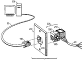
図1は、電気通信システムに使用された相互接続ハードウェアのアセンブリを開示している。このハードウェアは説明上、コード30、モジュラープラグ100およびモジュラージャック200などの標準通信接続装置を介して、高速コンピュータ装置300を電気ケーブル20に相互接続するために使用されている。そのようなプラグおよびジャックの仕様は、FCCパート68.500登録規則のサブパートFに示されている。モジュラージャック200は、互いに組み合わされてモジュラープラグ100を受け取って保持する好都合な受け部を形成するばねブロックアセンブリ210およびジャックハウジング220を備えている。ばねブロックアセンブリ210は、多数の導電路を含む。導電路の一端部は、たとえば、ベリリウム銅などの弾性材料製の可撓性ワイヤばね(以下の説明では「ジャックばね」)で終わっており、これらのワイヤばねは、モジュラープラグ内の金属ブレード120(図2を参照)の対応配列と電気接触するようにモジュラージャック内に配列されている。導電路の他端部は、ケーブル20内のワイヤと電気接触する絶縁変移コネクタ(insulation-displacement connector)で終わっている。周知のばねブロックアセンブリの例が、米国特許第5,041,018号および第5,096,442号に示されており、ジャックハウジング220の後端部にはめ込まれるように構成されている。
【0013】
ジャックハウジング220の前端部の開口225は、モジュラープラグ100を受け取る形状を有しており、モジュラープラグ100はそれに挿入されて保持される。しかし、モジュラープラグが片持ち式ラッチ130(図2を参照)によってモジュラージャック内にロックされるにしても、そのブレード120は、プラグがどの程度まで深く挿入されたかに応じて、一定の位置範囲内のいずれかの位置でジャックばねと接触するであろう。これは、位置変動として知られており、本発明はそれを減少または排除しようとするものである。また、位置変動は音声周波数通信では問題にならないが、もっと高い周波数では電気性能に悪影響を与える。モジュラージャック200を支持するためにしばしば壁板400が使用され、ジャックは該ジャックを保持するように設計された壁板の開口410内に取り付けられる。
【0014】
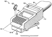
図2は、標準モジュラープラグ100の全体構造を示す斜視図である。モジュラープラグ100は、複数の端子受けスロットに挿入された多数の金属端子120を有する絶縁プラグハウジング110を含む。図2では、ハウジングの上側から下向きに、コード30からのワイヤを保持する導線受けダクト内まで延びた8個のそのようなスロット(101−1〜101−8)が設けられている。プラグハウジング110は、剛直な前表面135と導線ひずみ取り部材140とを含み、このひずみ取り部材140は、導線をプラグ内の室の底部に係合した状態に固定する組み立て中に下方にたわむことによって、導体のひずみ取りを行う。プラグハウジング100はさらに、ジャケットひずみ取り部材150を含み、これも組み立て中に下方にたわんで、コード30のジャケットのひずみ取りを行う。プラグ100をモジュラージャック200にロックするために、片持ち式ラッチ130が設けられている。ここで、本発明は、モジュラージャック200内でのモジュラープラグ100の軸方向移動を減少させるモジュラージャックの変更例を扱っていることに注意されたい。特に、モジュラージャック200は、標準モジュラープラグの軸方向移動を減少させることができる。
【0015】
近端漏話
発明の背景で説明したように、モジュラージャック内のペア導線間の漏話は、ジャック内に補償漏話を加えることによって、大幅に減少させることができる。補償漏話は、障害漏話の極性と逆の極性を有し、障害漏話を相殺するように慎重に導入される。さらに、(1)障害漏話にできる限り近い位置で補償漏話を導入すること、(2)モジュラージャック内の一定位置で補償漏話を導入することが重要である。これらの考慮から、高周波(すなわち100MHz以上の周波数)では、補償漏話の位相が短い距離で大きく変化すること、および伝播遅れのために障害漏話からの位相外れが正確に180度である補償漏話を導入することは実質的に不可能であることがわかる。このため、設計者は、ジャックばねがモジュラープラグ内のブレードと接触する位置にできる限り近い位置で補償漏話をモジュラージャック内に導入し、その位置を一定に保持してきた。本発明は、図3の実施形態に示されているようにして、これらの目標を達成する。
【0016】
図3は、コード30を取り付けたモジュラープラグ100をモジュラージャック200の前端部221の開口225にまさに挿入しようとするところの斜視図である。プラグ100をジャックの長手方向軸線201−201に沿って、開口225内へ前進させることによって、挿入が行われる。この構造は、プラグが後方保持表面214に押しつけられるまで、限定量のプラグ移動“d1”を与え、これが約0.033インチ(0.84ミリメートル)であることに注意されたい。プラグをジャック200内に完全に挿入すると、プラグブレード120が211で示された位置でジャックばね215と電気接触する。211および212間の領域に導入される障害漏話を最小限に抑えるために、位置211が位置212に近いことが望ましい。これらの位置の間の距離“d”が変動すると、相殺する必要がある障害漏話の大きさおよび位相が変化するため、正確な距離“d”を知ることが特に重要である。このため、距離“d”の変動を減少させることによって、障害漏話を相殺するために、モジュラージャックによって与えられる補償漏話をより正確に設計することができる。ジャックばね215の交差以外の技術によって、補償漏話を導入してもよく、また、プラグブレード120およびジャックばね215の間で電気接触する位置211の変動が減少することによって、利益を得るいずれのモジュラージャックにも、本発明を使用できることに注意されたい。
【0017】
本発明によれば、位置211の変動を減少させることによって、距離“d”の変動を減少させる。これは、挿入されたモジュラープラグ100を常に既知位置に着座させる位置決め部材をモジュラージャック200内に設けることによって達成される。プラグをジャックに挿入してから前後方向に押すと、やがてそれはその方向のそれ以上の移動を止める保持表面と出会う。図3および図4に示されている本発明の第1実施形態によれば、標準モジュラープラグのすべてに存在して、プラグをモジュラージャック200の前端部211の開口225にはめ込むことを可能にするためにたわむ可撓性片持ち式ラッチ130を有利に利用している。この実施形態では、位置決め部材は、片持ち式ラッチの傾斜(長手方向軸線201に対して約60゜の)表面131との相互作用によって、モジュラープラグをジャックハウジング220から押し出そうとする力“F1”を発生するカム228を含む。この力“F1”は、片持ち式ラッチ130が元のたわんでいない状態に戻ろうとする時の復元力によって発生する。しかし、ジャックハウジングには、片持ち式ラッチのストップ表面132に係合して、プラグがジャックハウジングから離脱するのを防止する前方保持表面229が設けられている。好都合なことに、プラグ100では、位置変動が減少する。モジュラープラグおよびジャックのFCC規格は、約0.033インチ(0.84ミリメートル)の軸方向位置自由を許容している。ジャックばね215を長手方向軸線201−201に対してたとえば17゜の鋭角φに配置した時、伝送路長さ“d”の実際の変動は約0.035インチ(0.89ミリメートル)である。距離“d”が約0.148インチ(3.76ミリメートル)である位置211および212の間の領域に追加の障害漏話が導入されるので、FCC許容位置変動が最大で0.035インチ(0.89ミリメートル)(すなわち23%)だけ除去され、同様に、その領域の障害漏話の変動が減少する。また、“F1”の方向によっては、障害漏話がわずかに増加するが、それは正確にわかるため、より正確に相殺することができる。
【0018】
図3および図4は、ジャックばね215をばねブロックアセンブリ210内にどのように取り付けるかについて特に示していないが、そのような詳細は本発明にとって重要ではなく、示すならば読者を混乱させると思われることに注意されたい。しかし、本発明の1つの実施形態の基本作動を説明したので、次にモジュラージャック200の実際の構造に関するさらなる詳細を明らかにする第2実施形態を示す。
【0019】
図5および図6は、モジュラージャック200の構造に関する詳細を明らかにする本発明の第2実施形態を示している。特に、モジュラージャック200は、ジャックハウジング200の後端部内に設置されたばねブロックアセンブリ210を有する。ジャックばね215は、上記のように補償漏話を与えるために選択ペア導線間に容量結合および誘導結合の両方またはいずれか一方を導入するための回路を含む構造体216に取り付けられている。1999年3月8日に出願された米国特許出願第09/264506号が、ばねブロックアセンブリ210の構造に関する詳細な情報を提供しており、参照として本明細書に援用される。第2実施形態では、位置決め部材は、説明例としてベリリウム銅などの金属材料製の弾性板ばね213を含み、これは、ばねブロックアセンブリ210の前端部分に取り付けられている。モジュラープラグ100、ジャックフレーム220およびばねブロックアセンブリ210を図6に示されているように互いに連結した時、可撓性板ばね213は、モジュラープラグ100の剛直前表面135と相互作用する位置にあって、モジュラープラグをジャックハウジング220から押し出そうとする力“F2”を発生する。この力“F2”は、ばね213が元のたわんでいない状態に戻ろうとする時の復元力によって発生する。しかし、ジャックハウジングには、片持ち式ラッチのストップ表面132に係合してプラグがジャックハウジングから離脱するのを防止する前方保持表面229が設けられている。好都合なことに、(ジャックばね215がプラグブレード120と接触する)位置211と(漏話補償を導入する)位置212との間の距離“d”が比較的一定である。したがって、この第2実施形態も、モジュラージャック内でモジュラープラグの望ましい一定の位置決めを行う。
【0020】
本発明の様々な特定の実施形態を示してきたが、本発明の範囲内で変更が可能である。これらの変更は、モジュラープラグをモジュラージャック内へさらに深く押し込む位置決め部材の使用、モジュラージャック内の多重位置決め部材の使用、位置決め部材としてゴムなどのエラストマー材料の使用、およびモジュラージャックの構造での本明細書に示されているもの以外の材料の使用を含むが、それらに制限されない。
【図面の簡単な説明】
【図1】電気通信システムに使用される相互接続ハードウェアのアセンブリを示す図である。
【図2】モジュラープラグの上側斜視図である。
【図3】本発明に従ったモジュラージャックの第1実施形態に挿入中のモジュラープラグの底側斜視図である。
【図4】モジュラープラグがモジュラージャックにはめ込まれた状態にある本発明の第1実施形態の断面図である。
【図5】本発明に従ったモジュラージャックの第2実施形態に挿入中のモジュラープラグの底側斜視図である。
【図6】モジュラープラグがモジュラージャックにはめ込まれた状態にある本発明の第2実施形態の断面図である。
【符号の説明】
100 モジュラープラグ
120 金属ブレード
200 モジュラージャック
213 板ばね
215 ジャックばね
225 開口
228 カム
229 保持表面[0001]
BACKGROUND OF THE INVENTION
The present invention relates to the electrical and physical structure of connectors, particularly modular jacks, used in telecommunications.
[0002]
[Prior art]
The term crosstalk was originally devised to represent the presence of unwanted conversational sound from another telephone conversation at the handset. Crosstalk caused by signal coupling between adjacent circuits is particularly critical. The most common coupling is due to near field effects and will usually be characterized by mutual inductance and direct capacitance. This is best explained by considering two parallel balanced transmission paths. One circuit (interfering circuit) is a signal energy source that is inconveniently coupled to adjacent circuits by stray capacitance and mutual inductance. Near-end crosstalk (NEXT) is crosstalk energy that moves in the opposite direction to the signal in the jamming circuit, while far-end crosstalk is crosstalk energy that moves in the same direction as the signal in the jamming circuit. Circuit analysis shows that NEXT is frequency dependent, and in the case of communication connectors, its size generally increases with frequency at a rate of 6.0 dB per octave. NEXT is introduced into electrical cables as a result of signal energy coupling between adjacent wires, and NEXT is introduced into electrical connectors, particularly modular plugs and jacks, as a result of signal energy coupling between adjacent wires. NEXT is undesirable and is often referred to as offending crosstalk.
[0003]
US Pat. No. 5,096,442 discloses a modular jack that is about 25 dB below the level of the signal that NEXT arrives at 100 MHz. Such NEXT is due to crosstalk introduced by combining a standard modular plug with a standard modular jack as commonly used for voice band communications. However, this crosstalk level is generally too high for modem high-speed data applications.
[0004]
U.S. Pat. No. 5,186,647 significantly improves the construction of a standard modular jack by crossing one conductor in the jack with another conductor in the jack to create a reverse polarity crosstalk. Disclosure. Such compensated crosstalk seeks to offset it rather than simply minimizing NEXT, for example, by increasing the separation between conductors. This simple technology improves NEXT at 100 MHz by 17 dB, which makes Category 5 the standard modular jack specified by ANSI / EIA (American National Standards Institute / Electronic Industry Association) / TIA-568A. Can meet the requirements. An example of such a modular jack is the M100 Communication Outlet manufactured by Lucent Technologies Inc.
[0005]
Techniques have been developed to further improve the crosstalk performance of electrical connectors, and NEXT is now more than 60 dB below the level of signals coming at 100 MHz. U.S. Pat. No. 5,997,358 shows such a technique. However, this crosstalk performance level represents the best achievable because the crosstalk varies depending on how the plug sits in the jack. At least one manufacturer places the jack spring in the modular jack with a relatively large contact angle (about 36 °) with respect to the longitudinal axis of the modular jack in order to push the modular plug into a fixed position in the jack. Yes. However, since there are many jack springs that need to be in electrical contact with the inserted modular plug blade, this connection becomes difficult at large contact angles. The large contact angle increases the pressure pushing the plug blade, but if all of the plug blades and jack springs are not exactly aligned, the increased pressure from some jack springs can cause the plugs to plug in with other jack springs. Contact with the blade may be hindered. In fact, the current FCC (US Federal Communications Commission) standard recommends a relatively small contact angle (ie, 13-24 °) to ensure that all plug blades are in contact with the jack spring. ing.
[0006]
[Problems to be solved by the invention]
Thus, what appears to be lacking in the prior art, and what is currently desired is to secure the modular plug within a modular jack that includes a jack spring disposed at a relatively small angle with respect to the longitudinal axis of the modular jack. This is a technique for positioning at a constant.
[0007]
[Means for Solving the Problems]
The modular jack includes a jack housing having an opening at the front end for receiving a modular plug. Within the opening are a number of jack springs that are in electrical contact with the metal blades that are fitted into the plug. By including a positioning member in the jack, the actual position variation where the plug blade contacts the jack spring is reduced. The locating member generates an axial force that engages the modular plug and pushes the plug toward a fixed retaining surface in the jack, thereby reducing positional variations between the plug and the jack contact surface.
[0008]
Since position variation affects the amount of crosstalk compensation required, reducing the position variation is particularly important in situations where the modular plug includes crosstalk compensation.
[0009]
In one illustrative embodiment, the positioning member includes a cam molded into the housing and positioned to engage a flexible latch on the modular plug. The interaction between the cam and the flexible latch generates an axial force that pushes the plug toward the fixed retaining surface in the housing. As a result, the plug is pushed into a known position in the jack.
[0010]
In another illustrative embodiment, the positioning member has a spring other than the jack spring, and this spring engages the rigid surface of the modular plug to generate an axial force that pushes the plug toward the fixed retaining surface. To do. Conveniently, in both embodiments, the improved modular jack is compatible with existing modular plugs.
[0011]
The invention and its mode of operation will be more clearly understood from the following detailed description when read in conjunction with the accompanying drawings.
[0012]
DETAILED DESCRIPTION OF THE INVENTION
FIG. 1 discloses an assembly of interconnect hardware used in a telecommunications system. This hardware is illustratively used to interconnect the high
[0013]
The
[0014]
FIG. 2 is a perspective view showing the overall structure of the standard
[0015]
Near-end crosstalk As explained in the background of the invention, crosstalk between paired wires in a modular jack can be greatly reduced by adding compensated crosstalk in the jack. Compensation crosstalk has a polarity opposite to that of fault crosstalk and is carefully introduced to offset the fault crosstalk. Furthermore, it is important to (1) introduce compensated crosstalk at a position as close as possible to the fault crosstalk, and (2) introduce compensated crosstalk at a fixed position in the modular jack. From these considerations, at high frequencies (ie, frequencies above 100 MHz), the compensation crosstalk changes significantly over short distances, and compensation crosstalk is exactly 180 degrees out of phase from fault crosstalk due to propagation delay. It turns out that it is virtually impossible to introduce. For this reason, designers have introduced compensating crosstalk into the modular jack as close as possible to the position where the jack spring contacts the blade in the modular plug, and has kept that position constant. The present invention achieves these goals as shown in the embodiment of FIG.
[0016]
FIG. 3 is a perspective view of the
[0017]
According to the present invention, the variation of the distance “d” is reduced by reducing the variation of the
[0018]
3 and 4 do not specifically show how the
[0019]
5 and 6 show a second embodiment of the present invention that reveals details regarding the structure of the
[0020]
While various specific embodiments of the invention have been shown, modifications can be made within the scope of the invention. These changes include the use of a positioning member that pushes the modular plug deeper into the modular jack, the use of multiple positioning members within the modular jack, the use of an elastomeric material such as rubber as the positioning member, and the present specification in the construction of the modular jack. Including, but not limited to, the use of materials other than those shown in the document.
[Brief description of the drawings]
FIG. 1 shows an assembly of interconnect hardware used in a telecommunications system.
FIG. 2 is a top perspective view of a modular plug.
FIG. 3 is a bottom perspective view of the modular plug being inserted into the first embodiment of the modular jack according to the present invention;
FIG. 4 is a cross-sectional view of the first embodiment of the present invention with the modular plug fitted into the modular jack.
FIG. 5 is a bottom perspective view of a modular plug being inserted into a second embodiment of a modular jack according to the present invention.
FIG. 6 is a cross-sectional view of a second embodiment of the present invention with the modular plug fitted into the modular jack.
[Explanation of symbols]
100
Claims (6)
Applications Claiming Priority (2)
| Application Number | Priority Date | Filing Date | Title |
|---|---|---|---|
| US09/465178 | 1999-12-15 | ||
| US09/465,178 US6224427B1 (en) | 1999-12-15 | 1999-12-15 | Modular jack having a plug-positioning member |
Publications (2)
| Publication Number | Publication Date |
|---|---|
| JP2001203038A JP2001203038A (en) | 2001-07-27 |
| JP3659487B2 true JP3659487B2 (en) | 2005-06-15 |
Family
ID=23846782
Family Applications (1)
| Application Number | Title | Priority Date | Filing Date |
|---|---|---|---|
| JP2000381154A Expired - Fee Related JP3659487B2 (en) | 1999-12-15 | 2000-12-15 | Modular jack with plug positioning member |
Country Status (6)
| Country | Link |
|---|---|
| US (1) | US6224427B1 (en) |
| EP (1) | EP1109268B1 (en) |
| JP (1) | JP3659487B2 (en) |
| AU (1) | AU778544B2 (en) |
| CA (1) | CA2326369C (en) |
| DE (1) | DE60040520D1 (en) |
Families Citing this family (14)
| Publication number | Priority date | Publication date | Assignee | Title |
|---|---|---|---|---|
| US6350158B1 (en) | 2000-09-19 | 2002-02-26 | Avaya Technology Corp. | Low crosstalk communication connector |
| US6454590B1 (en) | 2001-03-23 | 2002-09-24 | Avaya Technology Corp. | Positive connection system for high frequency communication connectors |
| US6796847B2 (en) | 2002-10-21 | 2004-09-28 | Hubbell Incorporated | Electrical connector for telecommunications applications |
| JP2005166522A (en) | 2003-12-04 | 2005-06-23 | Yazaki Corp | connector |
| US20050221678A1 (en) | 2004-02-20 | 2005-10-06 | Hammond Bernard Jr | Methods and systems for compensating for alien crosstalk between connectors |
| US7187766B2 (en) * | 2004-02-20 | 2007-03-06 | Adc Incorporated | Methods and systems for compensating for alien crosstalk between connectors |
| US10680385B2 (en) | 2004-02-20 | 2020-06-09 | Commscope Technologies Llc | Methods and systems for compensating for alien crosstalk between connectors |
| CA2464834A1 (en) | 2004-04-19 | 2005-10-19 | Nordx/Cdt Inc. | Connector |
| ES2244351B1 (en) * | 2005-02-21 | 2007-02-16 | Bsh Electrodomesticos España, S.A. | AIR CONDITIONER. |
| US20060223380A1 (en) * | 2005-04-05 | 2006-10-05 | Dell Products L.P. | Device for testing connectivity of a connector including spring contact pins |
| US20070275607A1 (en) * | 2006-05-04 | 2007-11-29 | Kwark Young H | Compensation for far end crosstalk in data buses |
| US8145442B2 (en) * | 2009-01-30 | 2012-03-27 | Synopsys, Inc. | Fast and accurate estimation of gate output loading |
| US9640924B2 (en) | 2014-05-22 | 2017-05-02 | Panduit Corp. | Communication plug |
| JP7232147B2 (en) * | 2019-07-22 | 2023-03-02 | 日本航空電子工業株式会社 | Modular plug and cable harness |
Family Cites Families (13)
| Publication number | Priority date | Publication date | Assignee | Title |
|---|---|---|---|---|
| US4497526A (en) * | 1983-03-28 | 1985-02-05 | Amp Incorporated | Circuit board housing having self-contained modular jack |
| US4997526A (en) * | 1985-03-19 | 1991-03-05 | Eic Laboratories, Inc. | Assaying for a biologically active component |
| US5041018A (en) | 1990-08-20 | 1991-08-20 | At&T Bell Laboratories | Electrical connector receptacle |
| US5096442A (en) | 1991-07-26 | 1992-03-17 | At&T Bell Laboratories | Compact electrical connector |
| US5186647A (en) | 1992-02-24 | 1993-02-16 | At&T Bell Laboratories | High frequency electrical connector |
| GB2269713B (en) * | 1992-04-08 | 1996-07-24 | Megahertz Corp | Media connector interface for use with a PCMCIA-architecture communications card and method |
| US5547401A (en) * | 1992-04-08 | 1996-08-20 | Megahertz Corporation | Media connector interface for use with a thin-architecture communications card |
| JP2602786B2 (en) * | 1994-11-14 | 1997-04-23 | インターナショナル・ビジネス・マシーンズ・コーポレイション | Connectors and electronic devices using the connectors |
| JPH09161874A (en) * | 1995-12-05 | 1997-06-20 | Mitsubishi Electric Corp | Connector for modular jack |
| US5997358A (en) * | 1997-09-02 | 1999-12-07 | Lucent Technologies Inc. | Electrical connector having time-delayed signal compensation |
| US6012953A (en) * | 1997-08-05 | 2000-01-11 | 3Com Corporation | Surface mountable electrical connector system |
| US5947772A (en) * | 1997-08-22 | 1999-09-07 | Lucent Technologies Inc. | Wire terminal block for communication connectors |
| US6095851A (en) * | 1997-11-17 | 2000-08-01 | Xircom, Inc. | Status indicator for electronic device |
-
1999
- 1999-12-15 US US09/465,178 patent/US6224427B1/en not_active Expired - Lifetime
-
2000
- 2000-11-20 CA CA002326369A patent/CA2326369C/en not_active Expired - Fee Related
- 2000-12-07 AU AU72093/00A patent/AU778544B2/en not_active Ceased
- 2000-12-14 DE DE60040520T patent/DE60040520D1/en not_active Expired - Lifetime
- 2000-12-14 EP EP00311209A patent/EP1109268B1/en not_active Expired - Lifetime
- 2000-12-15 JP JP2000381154A patent/JP3659487B2/en not_active Expired - Fee Related
Also Published As
| Publication number | Publication date |
|---|---|
| EP1109268A1 (en) | 2001-06-20 |
| EP1109268B1 (en) | 2008-10-15 |
| AU778544B2 (en) | 2004-12-09 |
| JP2001203038A (en) | 2001-07-27 |
| CA2326369C (en) | 2005-05-17 |
| US6224427B1 (en) | 2001-05-01 |
| AU7209300A (en) | 2001-06-21 |
| CA2326369A1 (en) | 2001-06-15 |
| DE60040520D1 (en) | 2008-11-27 |
Similar Documents
| Publication | Publication Date | Title |
|---|---|---|
| US9419391B2 (en) | Communication connector | |
| US6079996A (en) | Selectable compatibility electrical connector jack | |
| JP3659487B2 (en) | Modular jack with plug positioning member | |
| US5399107A (en) | Modular jack with enhanced crosstalk performance | |
| EP1022817B1 (en) | Selectable compatibility electrical connector jack | |
| JP3708849B2 (en) | Selectable interchangeable electrical connector assembly | |
| EP1045490B1 (en) | Selectable compatibility electrical connector assembly | |
| US8915757B2 (en) | Communications jacks having sliding contacts and/or contacts having insulative base members | |
| US6168472B1 (en) | Selectable compatibility electrical connector assembly | |
| EP1056164B1 (en) | Selectable compatibility electrical connector assembly | |
| EP1022819B1 (en) | Selectable compatibility electrical connector plug | |
| EP1045485B1 (en) | Selectable compatibility electrical connector plug | |
| WO2018038959A1 (en) | Communication connector having contact pads contacted by movable contact members | |
| WO1994008365A2 (en) | Wiring connection system including crosstalk compensating connector |
Legal Events
| Date | Code | Title | Description |
|---|---|---|---|
| A977 | Report on retrieval |
Free format text: JAPANESE INTERMEDIATE CODE: A971007 Effective date: 20031127 |
|
| A131 | Notification of reasons for refusal |
Free format text: JAPANESE INTERMEDIATE CODE: A131 Effective date: 20031203 |
|
| A601 | Written request for extension of time |
Free format text: JAPANESE INTERMEDIATE CODE: A601 Effective date: 20040303 |
|
| A602 | Written permission of extension of time |
Free format text: JAPANESE INTERMEDIATE CODE: A602 Effective date: 20040308 |
|
| A521 | Written amendment |
Free format text: JAPANESE INTERMEDIATE CODE: A523 Effective date: 20040601 |
|
| A131 | Notification of reasons for refusal |
Free format text: JAPANESE INTERMEDIATE CODE: A131 Effective date: 20040804 |
|
| A521 | Written amendment |
Free format text: JAPANESE INTERMEDIATE CODE: A523 Effective date: 20041014 |
|
| TRDD | Decision of grant or rejection written | ||
| A01 | Written decision to grant a patent or to grant a registration (utility model) |
Free format text: JAPANESE INTERMEDIATE CODE: A01 Effective date: 20050216 |
|
| A61 | First payment of annual fees (during grant procedure) |
Free format text: JAPANESE INTERMEDIATE CODE: A61 Effective date: 20050310 |
|
| R150 | Certificate of patent or registration of utility model |
Free format text: JAPANESE INTERMEDIATE CODE: R150 |
|
| FPAY | Renewal fee payment (event date is renewal date of database) |
Free format text: PAYMENT UNTIL: 20080325 Year of fee payment: 3 |
|
| FPAY | Renewal fee payment (event date is renewal date of database) |
Free format text: PAYMENT UNTIL: 20090325 Year of fee payment: 4 |
|
| FPAY | Renewal fee payment (event date is renewal date of database) |
Free format text: PAYMENT UNTIL: 20100325 Year of fee payment: 5 |
|
| FPAY | Renewal fee payment (event date is renewal date of database) |
Free format text: PAYMENT UNTIL: 20100325 Year of fee payment: 5 |
|
| FPAY | Renewal fee payment (event date is renewal date of database) |
Free format text: PAYMENT UNTIL: 20110325 Year of fee payment: 6 |
|
| FPAY | Renewal fee payment (event date is renewal date of database) |
Free format text: PAYMENT UNTIL: 20120325 Year of fee payment: 7 |
|
| FPAY | Renewal fee payment (event date is renewal date of database) |
Free format text: PAYMENT UNTIL: 20130325 Year of fee payment: 8 |
|
| FPAY | Renewal fee payment (event date is renewal date of database) |
Free format text: PAYMENT UNTIL: 20130325 Year of fee payment: 8 |
|
| FPAY | Renewal fee payment (event date is renewal date of database) |
Free format text: PAYMENT UNTIL: 20140325 Year of fee payment: 9 |
|
| R250 | Receipt of annual fees |
Free format text: JAPANESE INTERMEDIATE CODE: R250 |
|
| R250 | Receipt of annual fees |
Free format text: JAPANESE INTERMEDIATE CODE: R250 |
|
| R250 | Receipt of annual fees |
Free format text: JAPANESE INTERMEDIATE CODE: R250 |
|
| LAPS | Cancellation because of no payment of annual fees |