JP3658930B2 - Cooking pot lid - Google Patents
Cooking pot lid Download PDFInfo
- Publication number
- JP3658930B2 JP3658930B2 JP19178997A JP19178997A JP3658930B2 JP 3658930 B2 JP3658930 B2 JP 3658930B2 JP 19178997 A JP19178997 A JP 19178997A JP 19178997 A JP19178997 A JP 19178997A JP 3658930 B2 JP3658930 B2 JP 3658930B2
- Authority
- JP
- Japan
- Prior art keywords
- lid
- transparent glass
- handle
- outer peripheral
- peripheral member
- Prior art date
- Legal status (The legal status is an assumption and is not a legal conclusion. Google has not performed a legal analysis and makes no representation as to the accuracy of the status listed.)
- Expired - Lifetime
Links
Images


Landscapes
- Cookers (AREA)
Description
【0001】
【発明の属する技術分野】
本発明は、調理鍋の蓋に関するものである。
【0002】
【従来の技術とその課題】
調理中に調理鍋の中が見えれば調理の状況が把握でき、安心感もある。このため、蓋を透明ガラスで構成したものがあるが、従来の蓋は全部を透明ガラスで構成していた。従って、蓋を鍋本体に被せるときにその縁が強く接触して割れる危険があった。又、調理鍋の傍に置いたりするときにも注意しないと割れることがあった。
【0003】
本発明は、このような課題を解決するものであり、透明ガラスで蓋を構成するものの、その構造やこれに付ける把手を工夫して極力割れないようにしたものである。
【0004】
【課題を解決するための手段】
以上の課題の下、本発明は、胴部と蓋受け部とが設けられる鍋本体に被せられる調理鍋の蓋であって、この蓋が、胴部上方を覆う耐熱性の透明ガラスと、透明ガラスの外周に嵌着されて蓋受け部上に載置される金属製の外周部材と、外周部材に固定されて透明ガラスの上方を架橋する把手とから構成されるものであり、外周部材が、透明ガラスから胴部の内側近くに垂下する縦部と、縦部からやや上昇して蓋受け部まで延出する横部とで構成されるものであり、把手の両端が縦部に固定されるものであることを特徴とする調理鍋の蓋を提供する。
【0005】
この手段をとることにより、蓋のうち、鍋本体に接触するのは金属製の外周部材であるから、いくら強く接触しても割れることはない。又、把手は透明ガラスの上方を架橋するから、透明ガラスをガードしている。更に、蓋には以上の態様の外周部材と把手が存在することにより、これを裏返して置いたとき等にもガラスが物に直接触れるのを極力少なくする。
【0006】
そして、外周部材が、透明ガラスから胴部の内側近くに垂下する縦部と、縦部からやや上昇して蓋受け部まで延出する横部とで構成されるものであり、把手の両端が縦部に固定されるものであるので、縦部と横部との境界は胴部に沿って下方に突起していることから、蓋の裏面に付着した水滴等をここから滴下させることになり、しかも、この箇所は胴部の近くに存在するから、調理物の中央部に落とさず、味を低下させない。又、把手を外周部材の縦部に固定すれば、蓋受け部と添着する横部に歪みを発生させないし、把手が高温になるのを防ぐ。
【0007】
さらに、把手の全部又は一部が適当な間隔を有する二本の金属製の棒で構成されるものにすると、従来の蓋の天井部等に設けられる摘まみ式の把手と違って視界を遮らない。特に、把手の部分も棒が適当間隔あいているから、視界を遮らない。
【0008】
【発明の実施の形態】
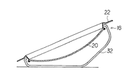
以下、本発明の実施の形態を図面を参照して説明する。図1は本発明の一例を示す調理鍋の縦断面図、図2は平面図、図3は要部断面図であるが、この調理鍋は、凹陥した胴部10と胴部10の上端を外方に張出させた蓋受け部12とからなる鍋本体14と、鍋本体14の上方に被せられる蓋16とで構成される。
【0009】
鍋本体14は、アルミとステンレスの複層体、アルミにフッ素樹脂等をコーティングしたもの、アルミの厚肉体といった厚肉金属で構成されるのが好ましい。胴部10内の温度分布を均平化できるとともに、蓋16との間でウォーターシールを生成できるからである。尚、胴部10の側面には、一つ又は二つの柄18が取り付けられる。
【0010】
蓋16は、胴部10上方を覆うボール状の耐熱性の透明ガラス20と、透明ガラス20の外周に嵌着されて蓋受け部12上に載置されるステンレス等の金属製の外周部材22とを主体とする。透明ガラス20と外周部材22との嵌着はかしめ等によればよく、例えば、透明ガラス20を外周部材22によって上方にも下方にも抜け出ないように保持すればよい。更に、このとき、接合部分にシール材24を介在させてシールを図るのが好ましい。
【0011】
透明ガラス20の部分は胴部10の内周近くまで存在させる。この部分をできるだけ広くして視界が開けるようにするためである。本例における外周部材22は、透明ガラス20から胴部10の内側近くに垂下する縦部26と、縦部26からやや上昇して蓋受け部12まで延出する横部28とで構成される。従って、縦部26と横部28との境界に下方突起30が胴部10に沿って形成されることになり、蓋16の裏面に付着した水滴等はこの下方突起30から滴下されることになる。本例では、下方突起30が胴部10の近くに存在するのであるから、水滴も胴部10の近くに落ちる。
【0012】
横部28は蓋受け部12にある程度の幅を保ってぴったりと添着するのが適する。気密性を保ち、ウォーターシールの生成を確実なものとするためである。この場合、横部28の外径と蓋受け部12の内径とをあまり違えないのが好ましいし、蓋受け部12の外端は若干上方に折曲して横部28のずれを止めるようにしておくのが好ましい。
【0013】
蓋16には外周部材22に固定されて透明ガラス20の上方を架橋する把手32が設けられる。本例の把手32はその両端が縦部26に溶接やビス止め等で固定される。固定の際に生ずる歪みを蓋受け部12と接触している横部28に発生させないためと、高温になっている横部28から離して温度を上げないためである。把手32の架橋の高さは、透明ガラス20との間に少なくとも手が入る程度は必要である。
【0014】
把手32の形状には種々のものが考えられるが、本例では、その全部又は一部が適当な間隔を有する二本の細い金属製の棒で構成されるものを採択した。棒の間から透明ガラス20の中を透視できるし、軽量化できるからである。この場合、棒は少なくとも真直な部分を有するものとし、これを下にして置くことができるものが適する。
【0015】
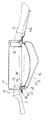
図4は把手32を下にして蓋16を置いたときの側面図、図5は正面図であるが、このような把手32にしておけば、裏返しておいたときにこの把手32が脚となって安定した姿勢を保てる。又、透明ガラス20に触れることなく、把手32部分のみを手で持って置いたり、持ち上げたりすることができる。更に、把手32と外周部材22とが下に接する斜めの姿勢で置いたとしても、透明ガラス20の部分を下に触れないようにすることができる。これらのことは、透明ガラス20の割れを防ぐ上で有効である。
【0016】
以上の蓋を使用すれば、透明ガラス20を通して調理中に胴部10の内部が透視できる。従って、調理の状況を把握できるとともに、安心感もある。この場合、把手32を二本の棒によるものにしておけば、視界を遮る部分がない。一方、蓋16の裏面に付着した水滴等は胴部10の近くの下方突起30から滴下するから、調理物の中央に落ちて味を低下させるといったことをなくす。
【0017】
ところで、上記した蓋16は鍋本体14に直接被せてもよいが、以下に説明する水受けリングを装着した調理鍋に使用すると更に有効である。図6はこの状態を示す調理鍋の縦断面図であるが、この水受けリング34は、蓋受け部12に載置される(従って、蓋16の横部28はこの上に載置されることになる)フランジ部36(36aは把手)と、胴部10内に垂下する水受けボックス38が適所に設けられてフランジ部36の内周から胴部10内に低下して中央側に上方傾斜で張出するリング部40とからなり、ステンレス板等で構成されるものである。
【0018】
この水受けリング34を鍋本体14に装着すると、蓋16の裏面に付着した水分が滴下するのを受け止めて(水分は下方突起30から滴下するから、リング部40がこの下に存在してこれを受け止める)胴部10内には落とさない。従って、胴部10の中に油を張る油料理でも蓋をして調理ができることになるのであるが、この蓋16によれば、これらの状況が見え、一層の安心感を与える。
【0019】
因みに、リング部40に落ちた水は水受けボックス38に流れ込み、ここで再蒸発を促される。尚、リング部40等を胴部10から離す構成にしておけば、リング部40があまり高温にならないから、この上に水が落ちたときに大きな蒸発音がしない。
【0020】
【発明の効果】
以上、本発明によれば、蓋のうち、鍋本体に接触するのは金属製の外周部材であるから、いくら強く接触しても割れることはない。又、把手は透明ガラスの上方を架橋するものであるから、ガラスをガードしている。更に、蓋には外周部材と把手が存在することにより、蓋を裏返して置いたとき等にもガラスが物に直接触れる事態を極力少なくする。一方、外周部材を設けたとしても、ガラスは鍋本体の胴部近くまで存在しているのであるから、視野を狭めることもない。
【図面の簡単な説明】
【図1】 本発明の一例を示す調理鍋の縦断面図である。
【図2】 本発明の一例を示す調理鍋の平面図である。
【図3】 本発明の一例を示す調理鍋の要部の断面図である。
【図4】 本発明の一例を示す蓋の断面図である。
【図5】 本発明の一例を示す蓋の正面図である。
【図6】 本発明の他の一例を示す調理鍋の縦断面図である。
【符号の説明】
10 胴部
12 蓋受け部
14 鍋本体
16 蓋
20 透明ガラス
22 外周部材
26 縦部
28 横部
32 把手[0001]
BACKGROUND OF THE INVENTION
The present invention relates to a cooking pan lid.
[0002]
[Prior art and its problems]
If you can see inside the cooking pan during cooking, you can grasp the cooking situation and feel secure. For this reason, some lids are made of transparent glass, but the conventional lids are all made of transparent glass. Therefore, there was a risk that the edge of the lid would come into strong contact and crack when covered with the pan body. In addition, there was a case where it was cracked if it was not careful when placing it near a cooking pot.
[0003]
The present invention solves such a problem, and although the lid is made of transparent glass, the structure and the handle attached thereto are devised so as not to break as much as possible.
[0004]
[Means for Solving the Problems]
Under the above problems, the present invention is a lid of a cooking pan that is placed on a pan body provided with a trunk portion and a lid receiving portion, and this lid is a heat-resistant transparent glass that covers the top of the trunk portion, and is transparent. fitted to the outer circumference of the glass are those composed of a metal hollow cylinder that is placed on the lid receptacle, and the handle bridging the upper transparent glass is fixed to the outer peripheral member, the peripheral member It consists of a vertical part that hangs from the transparent glass near the inside of the body part and a horizontal part that rises slightly from the vertical part and extends to the lid receiving part, and both ends of the handle are fixed to the vertical part. There is provided a cooking pot lid characterized by being a thing .
[0005]
By taking this means, it is the metal outer peripheral member that comes into contact with the pan body of the lid. Moreover, since the handle bridges the upper side of the transparent glass, the transparent glass is guarded. Furthermore, the presence of the outer peripheral member and the handle in the above-described manner on the lid minimizes the glass from touching the object as much as possible even when it is placed upside down.
[0006]
And an outer peripheral member is comprised by the vertical part which hangs down from the transparent glass near the inner side of a trunk | drum, and the horizontal part which raises a little from a vertical part and extends to a lid | cover receiving part, and both ends of a handle are Since it is fixed to the vertical part, the boundary between the vertical part and the horizontal part protrudes downward along the trunk part, so that water droplets etc. adhering to the back of the lid will be dropped from here. And since this location exists near the trunk | drum, it does not fall to the center part of a cooking thing, and does not reduce a taste. Further, if the handle is fixed to the vertical portion of the outer peripheral member, the lid receiving portion and the lateral portion to be attached are not distorted, and the handle is prevented from becoming hot.
[0007]
Furthermore , if the handle is entirely or partially composed of two metal rods with an appropriate interval, the field of view is blocked, unlike a conventional handle that is provided on the ceiling of the lid. Absent. In particular, the handle is not obstructed because the bars are properly spaced.
[0008]
DETAILED DESCRIPTION OF THE INVENTION
Hereinafter, embodiments of the present invention will be described with reference to the drawings. FIG. 1 is a longitudinal sectional view of a cooking pan showing an example of the present invention, FIG. 2 is a plan view, and FIG. 3 is a sectional view of the main part. This cooking pan has a
[0009]
The
[0010]
The
[0011]
The portion of the
[0012]
The
[0013]
The
[0014]
Various shapes of the
[0015]
FIG. 4 is a side view when the
[0016]
If the above lid | cover is used, the inside of the trunk | drum 10 can be seen through through the
[0017]
By the way, although the above-mentioned
[0018]
When the
[0019]
Incidentally, the water that has fallen on the ring portion 40 flows into the water receiving box 38, where it is prompted to re-evaporate. If the ring part 40 and the like are separated from the
[0020]
【The invention's effect】
As mentioned above, according to this invention, since it is a metal outer peripheral member which contacts a pan main body among lids, it does not crack even if it contacts even strongly. In addition, the handle guards the glass because it bridges the upper side of the transparent glass. Further, since the outer peripheral member and the handle are present on the lid, the situation where the glass directly touches an object even when the lid is turned over is minimized. On the other hand, even if the outer peripheral member is provided, since the glass exists up to the vicinity of the body of the pan body, the field of view is not narrowed.
[Brief description of the drawings]
FIG. 1 is a longitudinal sectional view of a cooking pan showing an example of the present invention.
FIG. 2 is a plan view of a cooking pan showing an example of the present invention.
FIG. 3 is a cross-sectional view of a main part of a cooking pan showing an example of the present invention.
FIG. 4 is a cross-sectional view of a lid showing an example of the present invention.
FIG. 5 is a front view of a lid showing an example of the present invention.
FIG. 6 is a longitudinal sectional view of a cooking pan showing another example of the present invention.
[Explanation of symbols]
DESCRIPTION OF
Claims (2)
Priority Applications (1)
| Application Number | Priority Date | Filing Date | Title |
|---|---|---|---|
| JP19178997A JP3658930B2 (en) | 1997-07-01 | 1997-07-01 | Cooking pot lid |
Applications Claiming Priority (1)
| Application Number | Priority Date | Filing Date | Title |
|---|---|---|---|
| JP19178997A JP3658930B2 (en) | 1997-07-01 | 1997-07-01 | Cooking pot lid |
Publications (2)
| Publication Number | Publication Date |
|---|---|
| JPH1118952A JPH1118952A (en) | 1999-01-26 |
| JP3658930B2 true JP3658930B2 (en) | 2005-06-15 |
Family
ID=16280574
Family Applications (1)
| Application Number | Title | Priority Date | Filing Date |
|---|---|---|---|
| JP19178997A Expired - Lifetime JP3658930B2 (en) | 1997-07-01 | 1997-07-01 | Cooking pot lid |
Country Status (1)
| Country | Link |
|---|---|
| JP (1) | JP3658930B2 (en) |
Families Citing this family (1)
| Publication number | Priority date | Publication date | Assignee | Title |
|---|---|---|---|---|
| JP2020188904A (en) * | 2019-05-21 | 2020-11-26 | 鳴海製陶株式会社 | pot lid |
-
1997
- 1997-07-01 JP JP19178997A patent/JP3658930B2/en not_active Expired - Lifetime
Also Published As
| Publication number | Publication date |
|---|---|
| JPH1118952A (en) | 1999-01-26 |
Similar Documents
| Publication | Publication Date | Title |
|---|---|---|
| US7617948B2 (en) | Cookware with multiple component lid | |
| JP3150132B2 (en) | Lid and handle assembly for cooking utensils | |
| US4700689A (en) | Cover for frying and cooking appliances | |
| US20040250690A1 (en) | Cooking vessel and lid therefor | |
| EP1240860B1 (en) | Cooking vessel | |
| CZ279911B6 (en) | Water jug | |
| US5377859A (en) | Cover for pan having variable conventional widths | |
| US20130112090A1 (en) | Shell-less egg-boiling utensil | |
| JP3658930B2 (en) | Cooking pot lid | |
| HU215273B (en) | Cooking-pan lid | |
| FI77970B (en) | LOCKFOERSETT KAERL MED REGLERBAR OEPPNING. | |
| US4590919A (en) | Cooking vessel with cover guard | |
| KR200405544Y1 (en) | oil scattering prevention and cooking lid | |
| JPH1085121A (en) | Rack for cooking pan | |
| JP3900635B2 (en) | Cooking pot lid | |
| KR200481116Y1 (en) | That cover close osculation and durability is improved frying pan | |
| JP2826070B2 (en) | Covered oil cooking pot | |
| JP4111476B2 (en) | Cooking pan with water ring | |
| CN212546569U (en) | Milk pot with steaming tray | |
| KR100479621B1 (en) | cover of frying pan | |
| KR200279277Y1 (en) | improved steamer | |
| KR200362248Y1 (en) | Improved model-cooking receptacle | |
| JP2802601B2 (en) | Pan spill prevention means | |
| KR100689265B1 (en) | A lid of a cooking vessel | |
| KR20170015737A (en) | Lid for pot |
Legal Events
| Date | Code | Title | Description |
|---|---|---|---|
| A621 | Written request for application examination |
Free format text: JAPANESE INTERMEDIATE CODE: A621 Effective date: 20040630 |
|
| A977 | Report on retrieval |
Free format text: JAPANESE INTERMEDIATE CODE: A971007 Effective date: 20040930 |
|
| A131 | Notification of reasons for refusal |
Free format text: JAPANESE INTERMEDIATE CODE: A131 Effective date: 20041109 |
|
| A521 | Written amendment |
Free format text: JAPANESE INTERMEDIATE CODE: A523 Effective date: 20050111 |
|
| TRDD | Decision of grant or rejection written | ||
| A01 | Written decision to grant a patent or to grant a registration (utility model) |
Free format text: JAPANESE INTERMEDIATE CODE: A01 Effective date: 20050303 |
|
| A61 | First payment of annual fees (during grant procedure) |
Free format text: JAPANESE INTERMEDIATE CODE: A61 Effective date: 20050307 |
|
| R150 | Certificate of patent or registration of utility model |
Free format text: JAPANESE INTERMEDIATE CODE: R150 |
|
| FPAY | Renewal fee payment (event date is renewal date of database) |
Free format text: PAYMENT UNTIL: 20080325 Year of fee payment: 3 |
|
| FPAY | Renewal fee payment (event date is renewal date of database) |
Free format text: PAYMENT UNTIL: 20110325 Year of fee payment: 6 |
|
| R250 | Receipt of annual fees |
Free format text: JAPANESE INTERMEDIATE CODE: R250 |
|
| R250 | Receipt of annual fees |
Free format text: JAPANESE INTERMEDIATE CODE: R250 |
|
| R250 | Receipt of annual fees |
Free format text: JAPANESE INTERMEDIATE CODE: R250 |
|
| EXPY | Cancellation because of completion of term |