JP3657341B2 - Injection molding method for refrigerator door and door inner plate - Google Patents
Injection molding method for refrigerator door and door inner plate Download PDFInfo
- Publication number
- JP3657341B2 JP3657341B2 JP03494596A JP3494596A JP3657341B2 JP 3657341 B2 JP3657341 B2 JP 3657341B2 JP 03494596 A JP03494596 A JP 03494596A JP 3494596 A JP3494596 A JP 3494596A JP 3657341 B2 JP3657341 B2 JP 3657341B2
- Authority
- JP
- Japan
- Prior art keywords
- inner plate
- bank
- door
- door inner
- Prior art date
- Legal status (The legal status is an assumption and is not a legal conclusion. Google has not performed a legal analysis and makes no representation as to the accuracy of the status listed.)
- Expired - Fee Related
Links
Images


Description
【0001】
【発明の属する技術分野】
この発明は冷蔵庫の扉の内面に形成された陥没部の内側面に、食品等を収容する、収容容器を支持するための冷蔵庫扉の収容容器支持構造に関するものである。
【0002】
【従来の技術】
図26、図27は例えば特開昭61−86575号公報に示された、従来の冷蔵庫の扉棚の要部斜視図および、要部断面図であり、図において、1は冷蔵庫の扉本体、2、3は上記扉本体を構成する扉外板と扉内板を示す。4は断熱材、5は取付ネジで、扉内板3を扉外板2に固定している。6は主に卵あるいは、缶詰等、比較的背の低い食品を収納するポケットで、後述するように、図28、図29に示すような方法で、扉内板3に取付けられている。前記扉内板3は、スチロール又はABS樹脂等のプラスチック板を真空成形加工したもので、両側に縦方向の土手3aが形成されている。
次に図28、図29により、ポケット6の取付構造を説明すると、前記扉内板土手3aにはその内側壁に係止突起7及び該係止突起7のやや上方位置に側面突起8が設けられていると共に、扉内板3の後壁には、横方向の土手3bが形成されている。9はポケット6の側面に設けられた係止溝で、前記扉内板土手の係止突起7に嵌合する。6aはポケット6の側面フランジで係止突起7のやや上方位置に設けられた側面突起8に図27に示す如く係止する。更に10はポケット6の両端に形成された裏側に肉ヌスミ部用凹10aを形成したツバ部で、ポケット6の係止溝9を扉内板土手3aの係止突起7に嵌合させた時、該ツバ部10が扉内板3の土手先端3cと当接するよう構成されている。
尚、前述のポケット6を扉内板3に取付けるためには、図27に示す位置よりポケット6を上方に置いて、ポケットのツバ部10を扉内板の土手先端3cに当接させた状態のまま下方に移動して扉内板土手3aの内側壁に設けられた側面突起8を弾性変形させながら、ポケット6を図29に示す位置まで下げる。
【0003】
【発明が解決しようとする課題】
従来の冷蔵庫扉のポケットの支持構造は以上のように構成されているので、ポケットを支持するためのポケットの係止溝9および、側面フランジ6aの板厚分食品収容側へ飛び出すので、土手3a間の内側間の本来、食品収容可能な範囲を、無駄なスペースと化しているとともに、扉内板土手3aとの当接用ツバ部10は肉ヌスミ用凹10aが形成されているので、近年流行の食品の視認性向上、ワイド感向上としての透明樹脂化した場合、内ヌスミ用凹10aが透けて見えてしまい、意匠性が低下する等の問題点があった。
【0004】
この発明は上記のような問題点を解消するためになされたもので、冷蔵庫扉のポケットを支持するための係止部を扉内板内側の食品収容側へ飛び出すこと無く、食品収容部を有効に活用できるとともに、近年流行のポケットの透明樹脂化に伴なう意匠性の低下を防ぐとともに、ポケットの着脱を簡単に確実に行なうことができる、冷蔵庫扉の収容容器支持構造の提供を目的とする。
【0005】
【課題を解決するための手段】
この発明に係る冷蔵庫扉は、冷蔵庫扉体の庫内側を構成する扉内板と、この扉内板の両側から立設した縦方向の土手と、それぞれの縦方向の土手内壁の前面から扉内板後壁に向かって設けられ、土手内壁を所定深さ落し込ませた土手段差部と、扉内板の後壁から立設し、土手段差部の下端付近から横に延びた横方向の土手と、この横方向の土手の上面に設けられた突起と、上面及び背面が開放した箱形状であり、底面に係止用凹溝を有し、土手段差部の前面から挿入され、横方向の土手の突起が係止用凹溝に嵌めこまれて係止されるポケットとを備えたことを特徴とする。
【0006】
また、この発明に係る冷蔵庫扉は、土手段差部の深さを、ポケットの側面部の厚さと同程度としたことを特徴とする。
【0007】
また、この発明に係る冷蔵庫扉は、土手段差部の後端縁部に係合用傾斜リブを設けるとともに、ポケット側面部の後端縁部に上下方向に係合用傾斜面を設け、ポケットが土手段差部に挿入された状態で、係合用傾斜面は係合用傾斜リブに係合されることを特徴とする。
【0008】
また、この発明に係る冷蔵庫扉は、土手段差部の上辺に係合用上辺傾斜リブを設けるとともに、ポケット側面部の上辺に係合用上辺傾斜面を設け、ポケットが土手段差部に挿入された状態で、係合用上辺傾斜面は係合用上辺傾斜リブに係合されることを特徴とする。
【0009】
また、この発明に係る冷蔵庫扉は、ポケット底面の係止用凹溝と前記ポケット後端との間に、前記横方向の土手に設けられた突起が前記ポケットに当接するのを防止する突起当接防止溝を設けたことを特徴とする請求項1記載の冷蔵庫扉。
【0010】
また、この発明に係る冷蔵庫扉は、ポケットは係止用凹溝を左右に有し、ポケット底面後端の左右の係止用凹溝間の中央部付近に係合用傾斜面を設けるとともに、扉内板にポケット底面後端とほぼ面一となるように形成された位置決め用段部に浮き上り防止リブを設け、係合用傾斜面は浮き上り防止リブに係合されることを特徴とする。
【0011】
また、この発明に係る冷蔵庫扉は、冷蔵庫扉体の庫内側を構成する扉内板と、この扉内板の両側から立設した縦方向の土手と、それぞれの縦方向の土手内壁の前面から扉内板後壁に向かって設けられ、土手内壁を所定深さ落し込ませた土手段差部と、この土手段差部に連なり、扉内板の後壁を所定深さ落し込ませた背面段差部と、扉内板の後壁から立設し、縦方向の土手に連なり、土手段差部の下端付近から横に延びた横方向の土手と、この横方向の土手に設けられたストッパー係合用凹部と、上面に係止用突起を有し、このストッパー係合用凹部に係合する、弾性変形の容易な樹脂製のストッパーと、上面が開放した箱形状であり、底面に係止穴を有し、土手段差部の前面から挿入され、ストッパーの係止用突起が係止穴に嵌めこまれて係止され、背面部が背面段差部まで挿入されるポケットとを備えたことを特徴とする。
【0013】
また、この発明に係る冷蔵庫扉は、扉内板の断熱材側に、扉内板と一体に断面形状がL 字状のアンカー片を形成したことを特徴とする。
【0014】
また、この発明に係る冷蔵庫扉は、扉内板の縦方向の土手内壁の断熱材側にアンカーリブを設けたことを特徴とする。
【0015】
また、この発明に係る冷蔵庫扉は、扉内板の外周フランジの断熱材側に凹状溝を形成したことを特徴とする。
また、この発明に係る冷蔵庫扉は、扉内板の外周フランジの断熱材側にパッキン部を形成したことを特徴とする。
また、この発明に係る冷蔵庫扉は、扉内板の断熱材側に切り起こし部を有する補強鉄板を設け、この切り起こし部をアンカー片に係合させたことを特徴とする。
【0016】
【発明の実施の形態】
実施の形態1.
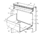
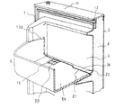
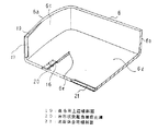
以下、この発明の一実施例を説明する。図1は、冷蔵室扉及び、この内面に支持されるポケットの要部断面斜視図。図2は図1のA−A断面図で、図3は図1の正面図であり、図4は図1のポケットを取り外した状態の要部断面斜視図。図5はポケットを背面から見た要部断面斜視図である。
1は冷蔵庫扉本体、2は扉外板、3は扉内板であり、PPまたはABS樹脂等により射出成形または射出圧縮成形により形成されている。4はポリウレタンフォーム等による現場発泡した断熱材である。11はドアキャップで、扉本体1の扉内板3側にドアガスケット(図示せず)を嵌合係止する押出成形によるドアサッシ12を保持するよう形成するとともに、扉外板2端面を覆うよう形成されている。冷蔵庫扉本体1は上述の部品により構成され、断熱材4の接着効果により各部品が強固に固着されている。
扉内板3は通常ABS等の真空成形にて形成されるが、真空成形ではシートを加熱して、真空圧による吸引力で、金型へシートを密着して成形する方式のため、シャープな形状や、シート厚さ以上の形状は形成不可能であり、この発明においては、射出成形または射出圧縮成形加工により細部形状を作成可能としている。3aは扉内板3の両側に縦方向に形成した土手である。3fは扉内板後壁であり、該後壁3fより横方向の土手3bが一体に形成されている。3cは土手先端である。3dは土手内壁であり、土手先端3cの厚さを薄くスマートに見せるための傾斜壁3eが形成されている。
6はポケットであり、6aは側面フランジ、6bは前面フランジ、6cは側面フランジ内壁、6dはポケット底面である。該ポケット底面6dの扉内板側にはポケット係止用凹溝16が形成されている。側面フランジ6a後端縁部にはポケット6の上下方向に係合用傾斜面17が形成されている。6eはポケット底面後端である。13はポケット側面フランジ6aの肉厚分とほぼ同一となるよう扉内板3の土手内壁3dを落し込ませた扉内板側面部の段落溝である土手段差部であり、該段差部13の後端には、ポケット6の上下方向に係合用傾斜面17と係合するよう扉内板の段落溝の後端縁部に係合用傾斜リブ14が併設されている。15は扉内板3のポケット下面側の横方向の土手3bに設けた台形状突起であり、ポケット底面6dの裏面に形成したポケット係止用凹溝16に係止するよう配置されている。3gはポケット底面後端6eとほぼ面一となるよう形成された、位置決め用段部である。
次にポケット6の扉内板3への装着について説明する。ポケット6を手に取り、側面フランジ6aを扉内板3の土手段差部13に沿わせるよう、前方より扉内板後壁3f側に挿入する。ポケット下面の扉内板側のポケット底面後端縁部6eが扉内板のポケット下面側の台形状突起15と当接すると、さらに強い力でポケット6を挿入することで、ポケット下面後端6eおよびポケット下面6dが、台形状突起15に乗り上げるよう弾性変形し、ポケット下面の扉内板側の係止用凹溝16に台形状突起15がはめ込まれると同時に、ポケット底面6dの弾性変形が解除され、ポケット係止用凹溝16と、台形状突起15が係止支持される。また、係合用傾斜面17は係合用傾斜リブ14に同時に係合されるよう形成されており、ポケット6の支持構造として左右の側面フランジ6aとポケット底面6dの3面で係止されるとともに、食品荷重に対してのポケット6のガタツキは、ポケット6の側面フランジ6aを扉内板3の土手段差部13に適度なクリアランスを保持しながら挿入嵌合しているので、ポケット6の全高を支持面とすることにより支持強度を向上している。次にポケット6の外し方について説明する。ポケット6の支持構造として、手前方向の係止はポケット底面6dのポケット係止用凹溝16と台形状突起15の係合のみのため、ポケット底面6dを、手前より指等で、上方に弾性変形させ、台形状突起15の係合を解除した状態で、ポケット6を手前に引き抜くことにより、ポケットの支持が解放される。
【0017】
本発明は以上のような冷蔵庫扉の収容容器支持構造を形成しているので、扉開閉時の回転モーメントにより、食品荷重がポケット前面フランジ6bに当接し、前方向にたわむとその反動で側面フランジ6aが、内側方向にたわもうとするが、係合用傾斜面17が、係合用傾斜リブ14に係止されているので、外れることなく安定に固着される。また土手内壁3dとポケット6の側面フランジ内壁6cがほぼ面一に形成されているので、食品収納有効面が、扉内板3の左右の土手内壁3d間全幅を利用でき、デッドスペースが発生しない。また従来のポケットのようにツバ部が無いため、透明樹脂によるポケットとした場合でも、意匠性が低下することなく、かつ、前述のようにポケット側面フランジ内壁6cと扉内板土手内壁3dがほぼ面一に形成されているので、清掃が容易等の効果を奏する。
【0018】
実施の形態2.
なお、上記実施の形態では扉内板3の土手段差部13の後端にのみ係合用傾斜リブ14を設けたものを示したが、図6〜図8の如く土手段差部上辺13aに係合用上辺傾斜リブ18を設け、相手側ポケット6の側面フランジ6aの上辺に、係合用上辺傾斜面19を設けても良い。この効果として、ポケット6を扉内板3へ装着する際、土手段差部13に沿わせて前方より、ポケット6の側面フランジ6aを装入する時、側面フランジ6a後端の係合用上辺傾斜面19の傾斜分、側面フランジ6aの高さが低いので、係合用傾斜面17が、扉内板3の係合用傾斜リブ14の位置まで挿入して初めて支持されるので、挿入時の挿入力が少なくて済むと共に、ポケット底面後端6eが、台形状突起15に乗り上げるよう弾性変形する間隔が少ないため、ポケット6の着脱に伴なう台形状突起15の摩耗の低下が図れる。
【0019】
実施の形態3.
また、ポケット下面6dのポケット係止用凹溝16と、ポケット下面後端6e間に台形状突起当接防止溝20を設けてもよい。よって、実施の形態2にて述べた、ポケット6の装着時の挿入力がより少なくて済む等の効果を奏する。
【0020】
実施の形態4.
また、ポケット6のポケット下面後端6eに左右のポケット係止用凹溝16間の中央部付近に係合用傾斜面21を設けるとともに相対応する扉内板3のポケット下面側に位置決め用段差部3gに、3角状の浮き上り防止リブ22を設けて係止させてもよく、ポケット6のポケット下面6dの射出成形時のソリ等による上方向へのハネ上がりによるポケット係止溝16への係合を確実に矯正する等の効果を奏する。
【0021】
実施の形態5.
上記実施の形態では、卵、缶詰め等比較的背の低い小物食品等の収容容器の支持構造について述べたが、瓶類等、背の高い、質量の大きな食品を収容する、いわゆるボトルポケットの支持構造について説明する。図9、図10において23はボトルポケットで、側面フランジ23aと前面フランジ23bと背面フランジ23fにより4辺が連結した容器状に形成されている。23dはボトルポケット下面で、ポケット係止穴24が穿設されている。23cは側面フランジ内壁である。23eは背面フランジ後端である。扉内板3の扉内板後壁3fには土手3aにある土手段差部13と同様に背面段差部25が連通して形成されている。26は上記扉内板のポケット下面側の横方向の土手3bに形成された、ストッパー係合用凹部であり、抜け止め用リブ26aおよび横方向の土手3bの土手先端3cには角穴26bが穿設されている。27は上記ポケット下面の扉内板側に設けられた、ボトルポケット23の係合用のストッパーであり、上述のストッパー係合用凹部26に嵌着し、脱落しないようフック27aが前方に形成され、角穴26bに係止される。27cは抜け止め用リブ26aと当接するよう配設した支持リブである。27bはボトルポケット底面23dに穿設したポケット係止穴24に係止するよう形成した、係止用突起である。ストッパー27は、例えばPPまたはPOM等弾性変形の容易な樹脂により射出成形することで、係止用突起27bを上面から押圧することで、容易に弾性変形し、下方へ傾斜するよう形成されている。次にボトルポケット23の扉内板3への装着について説明する。ボトルポケット23を手に取り側面フランジ23aを扉内板3の土手段差部13に沿わせるよう前方より、扉内板後壁3f側に挿入する。ボトルポケット底面23dが、係止用突起27bに当接すると、ボトルポケット底面23dの押圧力で、係止用突起27bが、下方へ傾斜するよう弾性変形し、ポケット係止穴24に係止用突起27bが嵌め込まれると同時に、係合用ストッパーの弾性変形が解除され、ポケット係止穴24に係止用突起27bが係止支持される。この状態では、実施の形態1にて述べた食品荷重による、側面フランジ23aの内側方向のたわみについては背面フランジ23eにより支持されるので、係合用傾斜面17や係合用傾斜リブ14等は不要である。ボトルポケット23の外し方は、係止用突起27bを指で押圧して、下方に弾性変形させポケット係止穴24の係合を解除した状態で手前に引き抜くことによりボトルポケット23の支持が解放される。
上記実施の形態では扉内板3とボトルポケット23の係合を、ポケット係止穴24と係止用突起27bにて、係止用突起27bをボトルポケット底面23d側より押圧するよう示したが、係合用ストッパー27側より、指を掛けて、係合、支持、解除するよう構成してもよい。また上記実施の形態ではボトルポケット23の背面フランジ23fを側面フランジ23aと同一の高さで示したが材料費削減によるコストダウンとして、両側面を残して傾斜または段差を付けて、低くしてもよく、要は扉内板後壁3fに形成した背面段差部の上端と、ボトルポケット23背面フランジ後端が係合すれば、食品収容時の支持強度が確保される。
【0022】
実施の形態6.
この発明における冷蔵庫扉のポケットの係合支持を、ポケット底部裏面側に扉内板とともに形成したことと、ポケットの側面フランジと扉内板、土手部内側が面一としたことで、収容容器の支持構造に伴うデッドスペースが発生しないとともに、ポケットのツバが不要なため、透明樹脂による意匠性の低下も防止できる。
【0023】
この発明に係る冷蔵庫扉の収容容器支持構造は、ポケットの着脱時の係止をポケット底部裏面と扉内板横方向の土手面に相互して形成した凹と凸による嵌合とするとともに、扉内板土手部をポケットの幅とほぼ同一でかつ、ポケットの側面フランジと面一にもぐり込ませるための断差部を形成し、ポケットの側面フランジ後端、縦壁部を扉内板とともにZ状嵌合を形成したものである。更にこの発明の製造方法の内、扉内板を射出成形または射出圧縮成形にて形成するものである。
【0024】
実施の形態7.
この発明は、冷蔵庫庫内側に複数の土手を設け、冷蔵庫庫外側(断熱材側)に複数のアンカー等を設けた冷蔵庫扉内板3に関するものであり、上記扉内板3は射出成形または射出圧縮成形にて成形したものである。
図12は上記射出成形による上記扉内板3の成形の流れを示したフローチャートである。図13は上記射出圧縮成形による上記扉内板3の成形の流れを示したフローチャートであり、相違点は、射出圧縮成形で、樹脂充填後に再度型締め工程を追加している。
図14はアンカー片30を成形するための構造を示す。上記射出成形及び上記射出圧縮成形法の要部工程を示す図であり、図14(a)は製品を取り出した後の型開き時であり、スライド駒36が右方向に移動している。図14(b)は型締め、樹脂充填時の工程を示し、スライド駒36が左方向に移動し、L字状の樹脂を充填するための空間部41が形成され、この空間部41に樹脂が充填されアンカー片30が扉内板3と一体に形成される。
図14(c)は製品(アンカー片30を一体に成形した扉内板3)取り出し時の工程を示し、スライド駒36は図14(a)と同様に右側へ移動しており、アンカー片30部分が、型開き時干渉しないよう構成されているので、扉内板3の取り出しが可能である。
上記の説明は射出成形及び射出圧縮成形のいづれにおいてもほぼ同様であるが、射出圧縮成形の特異な点を説明する。金型を予め隙間のある状態まで型締めし、その状態で樹脂を充填すると、隙間の分だけ樹脂の充填空間が拡大されるため樹脂の射出圧力が少なくて済む。また、この状態では、樹脂が金型全体に充填されないので、次に隙間を設けない状態まで圧縮するように型締めを行い、充填空間が拡大している部分に充填されている樹脂を金型全体に圧縮し移動させ、扉内板を成形する。
上記射出圧縮成形による扉内板3の成形法は、圧縮するための型締め工程が加わることにより、扉内板外周に形成された弾性変形の容易な断熱材シール用パッキン部等の薄肉部を設けても、圧縮による型締めによる樹脂充填は容易である。従来の射出成形では薄肉部へ樹脂を充填する場合、成形圧力を上げて樹脂充填をする必要があり、寸法のバラツキや充填不良が発生する等の不具合が生じるが、それを解消するものである。
図15(a)、図15(b)は従来の真空成形の成形法であり、加熱した樹脂シートを金型にのせ、吸気するものであるが、シートの板厚寸法のバラツキが生じる。
【0025】
実施の形態8.
図16は上記射出成形または上記射出圧縮成形により成形された扉内板3に一体に設けられたアンカー片30を備えた冷蔵庫扉の収容容器支持構造を示す図である。図において、30は断面がL字状であるアンカー片で、扉内板の横方向の土手3bの断熱材側に設けられたものである。
上記アンカー片30を設けることにより、断熱材をアンカー部に充填させ、扉内板と断熱材の密着強度をより向上させ、食品荷重などによる扉内板と断熱材との剥離方向の応力に対し、十分な強度を確保することができる。
【0026】
実施の形態9.
図17は上記射出成形または上記射出圧縮成形により成形された扉内板3に一体に設けられたアンカーリブ31を備えた冷蔵庫扉の収容容器横断面であり、図18は係合用傾斜リブ部14の詳細断面図である。図において、31はアンカーリブで、扉内板3の土手内壁3dの断熱材側に設けられたものである。
上記アンカーリブ31を設けることにより、扉内板3の土手部3dのポケット取付部の土手段差部の薄肉部を、アンカーリブ31を断熱材で保持することにより強度を向上させることができる。
【0027】
実施の形態10.
図19は上記射出成形または上記射出圧縮成形により成形された扉内板3に一体に設けられた凹状溝を備えた扉内板の断熱材側の斜視図である。図20は図19の要部斜視図であり、凹状溝32を示している。また、図21は凹状溝32を備えた冷蔵庫扉3の収容容器支持構造を示す図で、図22は図21の係合用ストッパー取付部のB−B断面図でありL字状のアンカー片30aの断面図である。図において、32は凹状溝で、扉内板3の外周フランジの断熱材側に凹状溝を形成したものである。
上記凹状溝32は、ドアサッシ12と、扉内板3外周との載置面からの断熱材の洩れを防止するために形成されたもので、凹凸形状になるよう凹状溝32を形成し、断熱材の洩れる沿面距離を延長することにより断熱材の洩れを凹凸の途中で止めることができる。
【0028】
実施の形態11.
図23(a)は上記射出成形または上記射出圧縮成形により成形された扉内板3に一体に設けられたパッキン部33を備えた扉内板の断熱材側の斜視図である。図23(b)は図23(a)の要部拡大斜視図であり、パッキン部33を拡大し詳細を示している。
上記パッキン部33を設けることにより、上記ドアサッシ12と、扉内板3外周との載置面からの断熱材の洩れ防止を確実にすることができ、PP等のオレフィン系材料を利用することで、弾性変形が容易なパッキン部33を形成し、断熱材充填発泡時の変形防止用の治具によりパッキン部33がフラットとなるよう押圧することで、パッキン部33が平坦になり、ドアサッシに密着することにより、シール性が改善される。
【0029】
実施の形態12.
図24は補強鉄板34、切り起こし部35を備えた扉内板の断熱材側の斜視図である。図は、扉内板3の断熱材側に配設した補強鉄板34に設けられた切り起こし部35を上記射出成形または上記射出圧縮成形により成形された扉内板3に一体に設けられたアンカー片30に係合させたものである。それにより、冷蔵庫扉として、断熱材の収縮に伴う、反り、ひねり等の変形を防止する目的で、装着する補強鉄板34をアンカー片30に係合させることで、固定するテープ等を廃止することができる。
図25(a)、図25(b)、図25(c)は補強鉄板34の取り付け方法を示し、扉内板3を側面から見た断面図である。補強鉄板34の切り起こし部35がL字状のアンカー片30の下端に当接すると、切り起こし部35が弾性変形し図の矢印方向に移動し、アンカー片30の下端を通過後、切り起こし部35が復帰することでアンカー片30の内側壁に当接されて、補強鉄板34が保持される。この係合構造を複数組配置し、係合方法を逆向きとすることで、位置決めが可能となる。
【0030】
【発明の効果】
この発明に係る冷蔵庫扉は、冷蔵庫扉のポケットを支持するための係止部を扉内板内側の食品収容側へ飛び出すこと無く、食品収容部を有効に活用できる。
【0031】
また、この発明に係る冷蔵庫扉は、土手内壁とポケットの側面内壁がほぼ面一に形成されているので、食品収納有効面が、扉内板の左右の土手内壁間全幅を利用でき、デッドスペースが発生しない。
【0032】
また、この発明に係る冷蔵庫扉は、扉開閉時の回転モーメントにより、食品荷重がポケット前面部に当接し、前方向にたわむとその反動で側面部が内側方向にたわもうとするが、係合用傾斜面が、係合用傾斜リブに係止されているので、外れることなく安定に固着される。
【0033】
また、この発明に係る冷蔵庫扉は、ポケットを扉内板に装着する際、土手段差部に沿わせて前方よりポケットの側面部を挿入する時、側面部後端の係合用上辺傾斜面の傾斜分、側面部の高さが低いので、係合用傾斜面が、扉内板の係合用傾斜リブの位置まで挿入して初めて支持されるので、挿入時の挿入力が少なくて済むと共に、ポケット底面後端が、突起に乗り上げるよう弾性変形する間隔が少ないため、ポケットの着脱に伴なう突起の摩耗の低下が図れる。
【0034】
また、この発明に係る冷蔵庫扉は、ポケット下面のポケット係止用凹溝と、ポケット下面後端間に台形状突起当接防止溝を設けたことにより、ポケットの装着時の挿入力がより少なくて済む等の効果を奏する。
【0035】
また、この発明に係る冷蔵庫扉は、ポケットのポケット下面の射出成形時のソリ等による上方向へのハネ上がりによるポケット係止部への係合を確実に矯正する等の効果を奏する。
【0036】
また、この発明に係る冷蔵庫扉は、冷蔵庫扉のポケットを支持するための係止部を扉内板内側の食品収容側へ飛び出すこと無く、食品収容部を有効に活用できるとともに、ポケットの着脱を簡単に確実に行なうことができる。
【0038】
また、この発明に係る冷蔵庫扉は、アンカー片を設けることにより、断熱材をアンカー部に充填させ、扉内板と断熱材の密着強度をより向上させ、食品荷重などによる扉内板と断熱材との剥離方向の応力に対し、十分な強度を確保することができる。
【0039】
また、この発明に係る冷蔵庫扉は、アンカーリブを設けることにより、扉内板土手部のポケット取付部の土手段差部の薄肉部を、アンカーリブを断熱材で保持することにより強度を向上させることができる。
【0040】
また、この発明に係る冷蔵庫扉は、凹凸形状になるよう凹状溝を形成し、断熱材の洩れる沿面距離を延長することにより断熱材の洩れを凹凸の途中で止めることができる。
【0041】
また、この発明に係る冷蔵庫扉は、パッキン部を設けることにより、ドアサッシと、扉内板外周との載置面からの断熱材の洩れ防止を確実にすることができる。
【0042】
また、この発明に係る冷蔵庫扉は、冷蔵庫扉として、断熱材の収縮に伴う、反り、ひねり等の変形を防止する目的で、装着する補強鉄板をアンカー片に係合させることで、固定するテープ等を廃止することができる。
【図面の簡単な説明】
【図1】 この発明の一実施例による冷蔵庫扉の収容容器支持構造を示す要部断面斜視図である。
【図2】 図1のA−A断面図である。
【図3】 図1の要部正面図である。
【図4】 図1に対応するポケットを取り外した状態を示す要部断面斜視図である。
【図5】 ポケット単体を背後側より示す要部断面斜視図である。
【図6】 他の実施例を示す、図1相当の要部断面斜視図である。
【図7】 他の実施例を示す、図4相当の要部断面斜視図である。
【図8】 他の実施例を示す、図5相当の要部断面斜視図である。
【図9】 他の実施例のボトルポケットの支持構造を示す要部断面斜視図である。
【図10】 図9に対応するボトルポケットを取り外した状態を示す要部断面斜視図である。
【図11】 図9の係合用ストッパー取付部のB−B断面図である。
【図12】 この発明の射出成形のフローチャート図である。
【図13】 この発明の射出圧縮成形のフローチャート図である。
【図14】 この発明の射出成形及び射出圧縮成形の成形法を示す図である。
【図15】 真空成形法を示す図である。
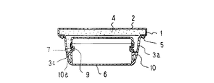
【図16】 冷蔵庫扉の収容容器支持構造を示す要部断面図である。
【図17】 この発明の冷蔵庫扉の収容容器断面図である。
【図18】 図17の係合用傾斜リブの詳細断面図である。
【図19】 この発明の扉内板の断熱材側の斜視図である。
【図20】 図19の要部斜視図である。
【図21】 この発明の冷蔵庫扉の収容容器断面図である。
【図22】 図21の係合用ストッパー取付部のB−B断面図である。
【図23】 この発明の扉内板の断熱材側の斜視図である。
【図24】 この発明の扉内板の断熱材側の斜視図である。
【図25】 この発明の補強鉄板を取付方法を示す、要部断面図である。
【図26】 従来の冷蔵庫扉の収容容器支持構造を示す、要部斜視図である。
【図27】 図26のD−D縦断面図である。
【図28】 図26のC−C横断面図である。
【図29】 図27のE−E縦断面図である。
【符号の説明】
1 扉本体、2 扉外板、3 扉内板、3a 土手、3b 横方向の土手、3c 土手先端、3d 土手内壁、3e 傾斜壁、3f 扉内板後壁、3g 位置決め用段部、4 断熱材、5 取付ネジ、6 ポケット、6a 側面フランジ、6b 前面フランジ、6c 側面フランジ内壁、6d ポケット底面、6e ポケット底面後端、7 係止突起、8 側面突起、9 係止溝、10 当接用ツバ部、10a 肉ヌスミ用凹、11 ドアキャップ、12 ドアサッシ、13 土手段差部、14 係合用傾斜リブ、15 台形状突起、16 ポケット係止用凹溝、17 係合用傾斜面、18 係合用上辺傾斜リブ、19 係合用上辺傾斜面、20 台形状突起当接防止溝、21 底面係合用傾斜面、22 浮き上り防止リブ、23 ボトルポケット、23a 側面フランジ、23b 前面フランジ、23d ボトルポケット底面、23e 背面フランジ後端、23f 背面フランジ、24 ポケット係止穴、25 背面段差部、26 ストッパー係合用凹部、26a 抜け止め用リブ、26b 角穴、27 係合用ストッパー、27a フック、27b 係止用突起、27c 支持リブ、30 L字状アンカー片、30a L字状アンカー片、31 アンカーリブ、32 凹状溝、33 パッキン部、34 補強鉄板、35 切り起こし部、36 駒、37 金型、38 金型、39 樹脂、40 樹脂シート、41 空間部。[0001]
BACKGROUND OF THE INVENTION
The present invention relates to a storage container support structure for a refrigerator door for supporting a storage container that stores food or the like on an inner surface of a depression formed on an inner surface of a refrigerator door.
[0002]
[Prior art]
FIGS. 26 and 27 are, for example, a main part perspective view and a main part cross-sectional view of a door shelf of a conventional refrigerator disclosed in Japanese Patent Application Laid-Open No. 61-86575, in which 1 is a door body of the refrigerator,
Next, the attachment structure of the
In order to attach the
[0003]
[Problems to be solved by the invention]
Since the conventional structure for supporting the pocket of the refrigerator door is configured as described above, the
[0004]
The present invention has been made to solve the above-described problems, and the food storage portion is effectively used without popping out the locking portion for supporting the pocket of the refrigerator door to the food storage side inside the door inner plate. The purpose is to provide a storage container support structure for refrigerator doors that can be used for the purpose of preventing the deterioration of the design properties associated with the recent trend of making pockets of transparent resin, and that allows easy and secure attachment and detachment of pockets. To do.
[0005]
[Means for Solving the Problems]
The refrigerator door according to the present invention includes a door inner plate constituting the inside of the refrigerator door body, a vertical bank erected from both sides of the door inner plate, and the interior of the door from the front of each vertical bank inner wall. The earth means difference part, which is provided toward the rear wall of the board and the inner wall of the bank is lowered to a predetermined depth, and the horizontal bank that is erected from the rear wall of the door inner board and extends laterally from near the lower end of the earth means difference part And a protrusion provided on the upper surface of the bank in the horizontal direction, and a box shape with the upper surface and the back surface open, and has a locking groove on the bottom surface, inserted from the front surface of the soil means difference portion, The bank is provided with a pocket in which a bank protrusion is fitted and locked in a locking groove.
[0006]
In addition, the refrigerator door according to the present invention is characterized in that the depth of the soil means difference portion is approximately the same as the thickness of the side surface portion of the pocket.
[0007]
In addition, the refrigerator door according to the present invention is provided with an engagement inclined rib at the rear end edge of the soil means difference portion, and an engagement inclined surface is provided in the vertical direction at the rear end edge of the pocket side surface portion, so that the pocket has an earth means difference. The engaging inclined surface is engaged with the engaging inclined rib while being inserted into the portion.
[0008]
Further, the refrigerator door according to the present invention is provided with the upper side inclined rib for engagement on the upper side of the soil means difference portion, the upper side inclined surface for engagement on the upper side of the pocket side surface portion, and the pocket being inserted into the soil means difference portion. The engaging upper side inclined surface is engaged with the engaging upper side inclined rib.
[0009]
Further, the refrigerator door according to the present invention is provided with a protrusion contact for preventing a protrusion provided on the horizontal bank from coming into contact with the pocket between the locking groove on the bottom surface of the pocket and the rear end of the pocket. The refrigerator door according to
[0010]
Further, the refrigerator door according to the present invention has a pocket having a locking groove on the left and right sides, an engagement inclined surface in the vicinity of the central portion between the left and right locking grooves on the rear end of the pocket bottom, and the door The positioning plate formed on the inner plate so as to be substantially flush with the rear end of the pocket bottom surface is provided with a lifting prevention rib, and the engaging inclined surface is engaged with the lifting prevention rib.
[0011]
Further, the refrigerator door according to the present invention includes a door inner plate constituting the inside of the refrigerator door body, a vertical bank erected from both sides of the door inner plate, and a front surface of each vertical bank inner wall. The earth means difference part that is provided toward the rear wall of the door inner plate and has the bank inner wall dropped to a predetermined depth, and the back step part that is connected to the earth means difference part and has the rear wall of the door inner plate dropped to a predetermined depth. And a horizontal bank extending from the rear wall of the door inner plate, connected to the vertical bank and extending laterally from the vicinity of the lower end of the bank means difference portion, and a stopper engaging recess provided on the horizontal bank And a stopper made of resin that is easily elastically deformed and has a locking projection on the top surface and engages with the stopper engaging recess, a box shape with the top surface open, and has a locking hole on the bottom surface. , Inserted from the front of the soil means difference portion, the stopper's locking projection is fitted into the locking hole and engaged Is characterized in that a pocket rear portion is inserted to the rear stepped portion.
[0013]
Moreover, the refrigerator door which concerns on this invention has cross-sectional shape L integrally with the door inner board in the heat insulating material side of the door inner board. A character-shaped anchor piece is formed.
[0014]
Moreover, the refrigerator door which concerns on this invention provided the anchor rib in the heat insulating material side of the bank inner wall of the vertical direction of a door inner board.
[0015]
The refrigerator door according to the present invention is characterized in that a concave groove is formed on the heat insulating material side of the outer peripheral flange of the door inner plate.
Moreover, the refrigerator door which concerns on this invention formed the packing part in the heat insulating material side of the outer peripheral flange of a door inner board, It is characterized by the above-mentioned.
The refrigerator door according to the present invention is characterized in that a reinforcing iron plate having a cut-and-raised portion is provided on the heat insulating material side of the door inner plate, and the cut-and-raised portion is engaged with an anchor piece.
[0016]
DETAILED DESCRIPTION OF THE INVENTION
An embodiment of the present invention will be described below. FIG. 1 is a cross-sectional perspective view of a main part of a refrigerator compartment door and a pocket supported by the inner surface. 2 is a cross-sectional view taken along the line AA of FIG. 1, FIG. 3 is a front view of FIG. 1, and FIG. 4 is a cross-sectional perspective view of a main part with the pocket of FIG. FIG. 5 is a cross-sectional perspective view of the main part when the pocket is viewed from the back.
The door
6 is a pocket, 6a is a side flange, 6b is a front flange, 6c is an inner wall of the side flange, and 6d is a bottom surface of the pocket. A pocket locking
Next, attachment of the
[0017]
Since the present invention forms the storage container support structure for the refrigerator door as described above, the food load abuts against the
[0018]
In the above embodiment, the
[0019]
Further, a trapezoidal protrusion
[0020]
Further, an engaging
[0021]
In the above embodiment, the supporting structure of the container for storing relatively small food items such as eggs and canned foods has been described. However, bottles and the like, which support tall and large food items, such as bottle pockets, are supported. The structure will be described. 9 and 10,
In the above embodiment, the door
[0022]
The engagement support of the pocket of the refrigerator door in this invention is formed with the door inner plate on the back side of the pocket bottom, and the side flange of the pocket, the door inner plate, and the bank portion inside are flush with each other. The dead space associated with the support structure does not occur, and the pocket brim is unnecessary, so that it is possible to prevent the design from being deteriorated by the transparent resin.
[0023]
The storage container support structure for a refrigerator door according to the present invention is a fitting with a concave and a convex formed on the back surface of the bottom of the pocket and the bank surface in the lateral direction of the door when the pocket is attached and detached. Forms a gap to allow the inner bank bank part to be almost the same as the pocket width and flush with the side flange of the pocket. The rear side flange of the pocket and the vertical wall part together with the door inner plate A shape-like fitting is formed. Further, in the manufacturing method of the present invention, the door inner plate is formed by injection molding or injection compression molding.
[0024]
The present invention relates to a refrigerator door
FIG. 12 is a flowchart showing a flow of molding the door
FIG. 14 shows a structure for forming the
FIG. 14C shows a process at the time of taking out the product (the door
The above description is substantially the same for both injection molding and injection compression molding, but the peculiar points of injection compression molding will be described. If the mold is clamped to a state with a gap in advance and the resin is filled in that state, the resin filling space is expanded by the gap, so that the injection pressure of the resin can be reduced. In this state, since the resin is not filled in the entire mold, the mold is then clamped so as to be compressed until no gap is provided, and the resin filled in the portion where the filling space is expanded is molded. Compressed and moved to form the door inner plate.
The molding method of the door
15 (a) and 15 (b) show a conventional vacuum forming method in which a heated resin sheet is placed on a mold and sucked, but variations in the sheet thickness of the sheet occur.
[0025]
Embodiment 8 FIG.
FIG. 16 is a view showing a storage container support structure for a refrigerator door provided with an
By providing the
[0026]
FIG. 17 is a cross-sectional view of a storage container of a refrigerator door provided with an
By providing the
[0027]
FIG. 19 is a perspective view of the heat insulating material side of the door inner plate provided with a concave groove integrally provided in the door
The
[0028]
FIG. 23A is a perspective view of the heat insulating material side of the door inner plate provided with a packing
By providing the packing
[0029]
FIG. 24 is a perspective view of the heat insulating material side of the door inner plate provided with the reinforcing
25 (a), 25 (b), and 25 (c) are cross-sectional views of the door
[0030]
【The invention's effect】
The refrigerator door which concerns on this invention can utilize a food storage part effectively, without jumping out the latching | locking part for supporting the pocket of a refrigerator door to the food storage side inside a door inner board.
[0031]
Further, the refrigerator door according to the present invention is such that the inner wall of the bank and the side wall of the pocket are substantially flush with each other, so that the food storage effective surface can use the full width between the left and right bank inner walls of the door inner plate, and dead space. Does not occur.
[0032]
In addition, the refrigerator door according to the present invention causes the food load to come into contact with the front surface portion of the pocket due to the rotational moment when the door is opened and closed, and when it bends forward, the side portion tends to bend inward due to the reaction. Since the combined inclined surface is locked to the engaging inclined rib, it can be stably fixed without coming off.
[0033]
Further, the refrigerator door according to the present invention, when the pocket is attached to the inner plate of the door, when the side surface portion of the pocket is inserted from the front along the soil means difference portion, the inclination of the upper side inclined surface for engagement at the rear end of the side surface portion Since the height of the side surface is low, the engaging inclined surface is supported only after being inserted to the position of the engaging inclined rib on the door inner plate, so that the insertion force during insertion can be reduced and the pocket bottom surface can be reduced. Since there are few intervals at which the rear end elastically deforms so as to ride on the protrusion, the wear of the protrusion accompanying the attachment / detachment of the pocket can be reduced.
[0034]
In addition, the refrigerator door according to the present invention is provided with a pocket locking concave groove on the lower surface of the pocket and a trapezoidal protrusion abutting prevention groove between the rear end of the lower surface of the pocket, thereby reducing the insertion force when the pocket is attached. There are effects such as ending.
[0035]
In addition, the refrigerator door according to the present invention has an effect of positively correcting the engagement with the pocket engaging portion due to the upward rising of the pocket by the warp during the injection molding of the pocket lower surface.
[0036]
In addition, the refrigerator door according to the present invention can effectively use the food storage portion without popping out the locking portion for supporting the pocket of the refrigerator door to the food storage side inside the door inner plate, and can be attached and detached from the pocket. It can be done easily and reliably.
[0038]
Moreover, the refrigerator door which concerns on this invention makes an anchor part fill with an anchor part by providing an anchor piece, improves the adhesive strength of a door inner board and a heat insulating material more, and the door inner board and heat insulating material by a food load etc. A sufficient strength can be secured against the stress in the peeling direction.
[0039]
Moreover, the refrigerator door which concerns on this invention improves an intensity | strength by hold | maintaining the thin part of the earth means difference part of the pocket attachment part of a board inner bank bank part with a heat insulating material by providing an anchor rib. Can do.
[0040]
Moreover, the refrigerator door which concerns on this invention can stop the leakage of a heat insulating material in the middle of an unevenness | corrugation by forming a concave groove | channel so that it may become uneven | corrugated shape, and extending the creeping distance from which a heat insulating material leaks.
[0041]
Moreover, the refrigerator door which concerns on this invention can ensure the leak prevention of the heat insulating material from the mounting surface of a door sash and a door inner board outer periphery by providing a packing part.
[0042]
Moreover, the refrigerator door which concerns on this invention is a tape which fixes as a refrigerator door by engaging the reinforcement iron plate to mount | wear with an anchor piece in order to prevent deformation | transformation of a curvature, a twist, etc. accompanying the shrinkage | contraction of a heat insulating material. Etc. can be abolished.
[Brief description of the drawings]
FIG. 1 is a cross-sectional perspective view showing a main part of a storage container support structure for a refrigerator door according to an embodiment of the present invention.
FIG. 2 is a cross-sectional view taken along the line AA of FIG.
FIG. 3 is a front view of main parts of FIG. 1;
FIG. 4 is a cross-sectional perspective view of a main part showing a state in which a pocket corresponding to FIG. 1 is removed.
FIG. 5 is a cross-sectional perspective view of a main part showing a single pocket from the back side.
6 is a cross-sectional perspective view of an essential part corresponding to FIG. 1, showing another embodiment.
7 is a cross-sectional perspective view of an essential part corresponding to FIG. 4, showing another embodiment.
FIG. 8 is a cross-sectional perspective view of a main part corresponding to FIG. 5, showing another embodiment.
FIG. 9 is a cross-sectional perspective view of a main part showing a support structure for a bottle pocket according to another embodiment.
10 is a cross-sectional perspective view of a main part showing a state where a bottle pocket corresponding to FIG. 9 is removed. FIG.
11 is a cross-sectional view taken along the line BB of the engaging stopper mounting portion of FIG. 9;
FIG. 12 is a flowchart of injection molding according to the present invention.
FIG. 13 is a flowchart of injection compression molding according to the present invention.
FIG. 14 is a view showing molding methods of injection molding and injection compression molding according to the present invention.
FIG. 15 is a diagram showing a vacuum forming method.
FIG. 16 is a cross-sectional view of the main part showing the storage container support structure for the refrigerator door.
FIG. 17 is a sectional view of the storage container of the refrigerator door according to the present invention.
18 is a detailed cross-sectional view of the engaging inclined rib of FIG. 17;
FIG. 19 is a perspective view of the heat insulating material side of the door inner plate according to the present invention.
20 is a perspective view of main parts of FIG.
FIG. 21 is a sectional view of the storage container of the refrigerator door according to the present invention.
22 is a cross-sectional view taken along the line BB of the engaging stopper mounting portion of FIG. 21. FIG.
FIG. 23 is a perspective view of the door inner plate of the present invention on the heat insulating material side.
FIG. 24 is a perspective view of the heat insulating material side of the door inner plate according to the present invention.
FIG. 25 is a cross-sectional view of an essential part showing a method for attaching the reinforcing iron plate of the present invention.
FIG. 26 is a perspective view of a main part showing a conventional container support structure for a refrigerator door.
27 is a DD longitudinal sectional view of FIG. 26. FIG.
28 is a cross-sectional view taken along the line CC of FIG.
29 is a vertical sectional view taken along line EE in FIG. 27. FIG.
[Explanation of symbols]
1 door body, 2 door outer plate, 3 door inner plate, 3a bank, 3b horizontal bank, 3c bank tip, 3d bank inner wall, 3e inclined wall, 3f door inner plate rear wall, 3g positioning step, 4 heat insulation Material 5 Mounting screw 6 Pocket 6a Side flange 6b Front flange 6c Side flange inner wall 6d Pocket bottom 6e Pocket bottom rear end 7 Locking protrusion 8 Side protrusion 9 Locking groove 10 For contact Recessed part, 10a Recess for meat pus, 11 Door cap, 12 Door sash, 13 Soil means difference part, 14 Engagement inclined rib, 15 Trapezoidal protrusion, 16 Pocket locking recessed groove, 17 Engagement inclined surface, 18 Engagement upper side Inclined rib, 19 Upper inclined surface for engagement, 20 Trapezoidal protrusion contact prevention groove, 21 Inclined surface for bottom surface engagement, 22 Lifting prevention rib, 23 Bottle pocket, 23a Side flange G, 23b Front flange, 23d Bottle pocket bottom, 23e Rear flange rear end, 23f Rear flange, 24 Pocket locking hole, 25 Back step, 26 Stopper recess, 26a Retaining rib, 26b Square hole, 27 Stopper, 27a hook, 27b locking projection, 27c support rib, 30 L-shaped anchor piece, 30a L-shaped anchor piece, 31 anchor rib, 32 concave groove, 33 packing part, 34 reinforcing iron plate, 35 cut and raised part 36 pieces, 37 molds, 38 molds, 39 resin, 40 resin sheets, 41 spaces.
Claims (12)
この扉内板の両側から立設した縦方向の土手と、
それぞれの縦方向の土手内壁の前面から扉内板後壁に向かって設けられ、前記土手内壁を所定深さ落し込ませた土手段差部と、
前記扉内板の後壁から立設し、前記土手段差部の下端付近から横に延びた横方向の土手と、
この横方向の土手の上面に設けられた突起と、
上面及び背面が開放した箱形状であり、底面に係止用凹溝を有し、前記土手段差部の前面から挿入され、前記横方向の土手の突起が該係止用凹溝に嵌めこまれて係止されるポケットと、
を備えたことを特徴とする冷蔵庫扉。A door inner plate constituting the inside of the refrigerator door body,
A vertical bank erected from both sides of the door inner plate,
A bank means difference portion provided from the front of each vertical bank inner wall toward the rear wall of the door inner plate, and having the bank inner wall dropped into a predetermined depth;
Standing from the rear wall of the door inner plate, a horizontal bank extending laterally from near the lower end of the earth means difference portion,
A protrusion provided on the upper surface of the horizontal bank,
It has a box shape with the top and back open, has a locking groove on the bottom, is inserted from the front of the soil means difference portion, and the projection on the horizontal bank is fitted into the locking groove. And pockets to be locked
A refrigerator door characterized by comprising:
この扉内板の両側から立設した縦方向の土手と、
それぞれの縦方向の土手内壁の前面から扉内板後壁に向かって設けられ、前記土手内壁を所定深さ落し込ませた土手段差部と、
この土手段差部に連なり、前記扉内板の後壁を所定深さ落し込ませた背面段差部と、
前記扉内板の後壁から立設し、前記縦方向の土手に連なり、土手段差部の下端付近から横に延びた横方向の土手と、
この横方向の土手に設けられたストッパー係合用凹部と、
上面に係止用突起を有し、このストッパー係合用凹部に係合する、弾性変形の容易な樹脂製のストッパーと、
上面が開放した箱形状であり、底面に係止穴を有し、前記土手段差部の前面から挿入され、前記ストッパーの係止用突起が該係止穴に嵌めこまれて係止され、背面部が前記背面段差部まで挿入されるポケットと、
を備えたことを特徴とする冷蔵庫扉。A door inner plate constituting the inside of the refrigerator door body,
A vertical bank erected from both sides of the door inner plate,
A bank means difference portion provided from the front of each vertical bank inner wall toward the rear wall of the door inner plate, and having the bank inner wall dropped into a predetermined depth;
A back step portion that is connected to the soil means difference portion and has the rear wall of the door inner plate dropped into a predetermined depth;
Standing from the rear wall of the inner plate of the door, connected to the vertical bank, a horizontal bank extending laterally from the vicinity of the lower end of the bank means difference portion,
A recess for engaging the stopper provided on the bank in the lateral direction;
A stopper made of resin that has a locking projection on the upper surface and engages with the stopper engaging recess, and that is easily elastically deformed;
It has a box shape with an open top surface, has a locking hole on the bottom surface, is inserted from the front surface of the soil means difference portion, and the locking projection of the stopper is fitted into the locking hole and locked, and the back surface A pocket into which the part is inserted up to the back step part,
A refrigerator door characterized by comprising:
Priority Applications (1)
| Application Number | Priority Date | Filing Date | Title |
|---|---|---|---|
| JP03494596A JP3657341B2 (en) | 1996-01-25 | 1996-02-22 | Injection molding method for refrigerator door and door inner plate |
Applications Claiming Priority (3)
| Application Number | Priority Date | Filing Date | Title |
|---|---|---|---|
| JP8-11075 | 1996-01-25 | ||
| JP1107596 | 1996-01-25 | ||
| JP03494596A JP3657341B2 (en) | 1996-01-25 | 1996-02-22 | Injection molding method for refrigerator door and door inner plate |
Publications (2)
| Publication Number | Publication Date |
|---|---|
| JPH09264663A JPH09264663A (en) | 1997-10-07 |
| JP3657341B2 true JP3657341B2 (en) | 2005-06-08 |
Family
ID=26346460
Family Applications (1)
| Application Number | Title | Priority Date | Filing Date |
|---|---|---|---|
| JP03494596A Expired - Fee Related JP3657341B2 (en) | 1996-01-25 | 1996-02-22 | Injection molding method for refrigerator door and door inner plate |
Country Status (1)
| Country | Link |
|---|---|
| JP (1) | JP3657341B2 (en) |
Cited By (2)
| Publication number | Priority date | Publication date | Assignee | Title |
|---|---|---|---|---|
| WO2019166367A1 (en) * | 2018-03-01 | 2019-09-06 | BSH Hausgeräte GmbH | Injection-moulded domestic-appliance component with inner door wall and door-mounted shelf |
| US20220221216A1 (en) * | 2021-01-11 | 2022-07-14 | Lg Electronics Inc. | Refrigerator |
-
1996
- 1996-02-22 JP JP03494596A patent/JP3657341B2/en not_active Expired - Fee Related
Cited By (2)
| Publication number | Priority date | Publication date | Assignee | Title |
|---|---|---|---|---|
| WO2019166367A1 (en) * | 2018-03-01 | 2019-09-06 | BSH Hausgeräte GmbH | Injection-moulded domestic-appliance component with inner door wall and door-mounted shelf |
| US20220221216A1 (en) * | 2021-01-11 | 2022-07-14 | Lg Electronics Inc. | Refrigerator |
Also Published As
| Publication number | Publication date |
|---|---|
| JPH09264663A (en) | 1997-10-07 |
Similar Documents
| Publication | Publication Date | Title |
|---|---|---|
| US7300120B2 (en) | Mounting structure of door basket for refrigerator | |
| US9308677B2 (en) | Door of refrigerator and method for manufacturing the same | |
| CN100375878C (en) | Method for manufacturing refrigerator and refrigerator door | |
| KR100633027B1 (en) | A inner cabinet of refrigerator and a mold for making thereof | |
| US6138432A (en) | Refrigerator door construction | |
| JP3657341B2 (en) | Injection molding method for refrigerator door and door inner plate | |
| JP3871500B2 (en) | Refrigerator door | |
| US20070145874A1 (en) | Refrigerator | |
| KR101060104B1 (en) | Incase for fridge | |
| CN112498965A (en) | Sealed locking buckle assembled lid and sealed container | |
| KR100678677B1 (en) | Device for sealing home bar for refrigerator | |
| CN218495592U (en) | Refrigerator trim with anti-deformation effect | |
| JP2016169928A (en) | Heat insulation door of refrigerator and manufacturing method of the same | |
| JP2724798B2 (en) | Insulated door and method of manufacturing the same | |
| JP4031993B2 (en) | refrigerator | |
| JP4457385B2 (en) | Sealed container made of synthetic resin | |
| CN106152680B (en) | Interior door body and fridge-freezer with the interior door body | |
| CN218120339U (en) | Mouth frame structure and freezer | |
| JP3665949B2 (en) | Refrigerator refrigerator door and refrigerator refrigerator using this drawer door | |
| EP3063483B1 (en) | Refrigerator door and method of manufacturing the same | |
| CN220411249U (en) | Combined cold chain box | |
| JPS6215334B2 (en) | ||
| CN110668009B (en) | Buffering liner and packaging structure with same | |
| KR200213445Y1 (en) | a cup for bottle | |
| JP5255423B2 (en) | refrigerator |
Legal Events
| Date | Code | Title | Description |
|---|---|---|---|
| RD01 | Notification of change of attorney |
Free format text: JAPANESE INTERMEDIATE CODE: A7421 Effective date: 20040715 |
|
| A977 | Report on retrieval |
Free format text: JAPANESE INTERMEDIATE CODE: A971007 Effective date: 20040830 |
|
| A131 | Notification of reasons for refusal |
Free format text: JAPANESE INTERMEDIATE CODE: A131 Effective date: 20040914 |
|
| RD01 | Notification of change of attorney |
Free format text: JAPANESE INTERMEDIATE CODE: A7421 Effective date: 20041102 |
|
| A521 | Written amendment |
Free format text: JAPANESE INTERMEDIATE CODE: A523 Effective date: 20041109 |
|
| A02 | Decision of refusal |
Free format text: JAPANESE INTERMEDIATE CODE: A02 Effective date: 20041207 |
|
| A521 | Written amendment |
Free format text: JAPANESE INTERMEDIATE CODE: A523 Effective date: 20050119 |
|
| A911 | Transfer of reconsideration by examiner before appeal (zenchi) |
Free format text: JAPANESE INTERMEDIATE CODE: A911 Effective date: 20050215 |
|
| TRDD | Decision of grant or rejection written | ||
| A01 | Written decision to grant a patent or to grant a registration (utility model) |
Free format text: JAPANESE INTERMEDIATE CODE: A01 Effective date: 20050308 |
|
| A61 | First payment of annual fees (during grant procedure) |
Free format text: JAPANESE INTERMEDIATE CODE: A61 Effective date: 20050309 |
|
| R150 | Certificate of patent or registration of utility model |
Free format text: JAPANESE INTERMEDIATE CODE: R150 |
|
| FPAY | Renewal fee payment (event date is renewal date of database) |
Free format text: PAYMENT UNTIL: 20080318 Year of fee payment: 3 |
|
| FPAY | Renewal fee payment (event date is renewal date of database) |
Free format text: PAYMENT UNTIL: 20090318 Year of fee payment: 4 |
|
| FPAY | Renewal fee payment (event date is renewal date of database) |
Free format text: PAYMENT UNTIL: 20100318 Year of fee payment: 5 |
|
| FPAY | Renewal fee payment (event date is renewal date of database) |
Free format text: PAYMENT UNTIL: 20100318 Year of fee payment: 5 |
|
| FPAY | Renewal fee payment (event date is renewal date of database) |
Free format text: PAYMENT UNTIL: 20110318 Year of fee payment: 6 |
|
| FPAY | Renewal fee payment (event date is renewal date of database) |
Free format text: PAYMENT UNTIL: 20110318 Year of fee payment: 6 |
|
| FPAY | Renewal fee payment (event date is renewal date of database) |
Free format text: PAYMENT UNTIL: 20120318 Year of fee payment: 7 |
|
| FPAY | Renewal fee payment (event date is renewal date of database) |
Free format text: PAYMENT UNTIL: 20130318 Year of fee payment: 8 |
|
| FPAY | Renewal fee payment (event date is renewal date of database) |
Free format text: PAYMENT UNTIL: 20130318 Year of fee payment: 8 |
|
| FPAY | Renewal fee payment (event date is renewal date of database) |
Free format text: PAYMENT UNTIL: 20140318 Year of fee payment: 9 |
|
| LAPS | Cancellation because of no payment of annual fees |