JP3657166B2 - Piezoelectric knock sensor - Google Patents
Piezoelectric knock sensor Download PDFInfo
- Publication number
- JP3657166B2 JP3657166B2 JP2000046492A JP2000046492A JP3657166B2 JP 3657166 B2 JP3657166 B2 JP 3657166B2 JP 2000046492 A JP2000046492 A JP 2000046492A JP 2000046492 A JP2000046492 A JP 2000046492A JP 3657166 B2 JP3657166 B2 JP 3657166B2
- Authority
- JP
- Japan
- Prior art keywords
- piezoelectric
- knock sensor
- sensing member
- vibration sensing
- piezoelectric element
- Prior art date
- Legal status (The legal status is an assumption and is not a legal conclusion. Google has not performed a legal analysis and makes no representation as to the accuracy of the status listed.)
- Expired - Fee Related
Links
Images

Landscapes
- Measurement Of Mechanical Vibrations Or Ultrasonic Waves (AREA)
- Combined Controls Of Internal Combustion Engines (AREA)
Description
【0001】
【発明の属する技術分野】
本発明は、内燃機関のシリンダ等に固結して、該シリンダ内のノッキングの発生を検出するために用いられる圧電ノックセンサに関するものである。
【0002】
【従来の技術】
圧電素子を備える振動感知部材を、金属製取付ケースの上面が開口する収納凹部の底面に、中心支持してなるものにおいて、金属製取付ケース内に支持してなる圧電ノックセンサは種々提案されている。この種の圧電ノックセンサとしては、圧電素子と重りとを積層してなる素子を備える振動感知部材を備えた非共振型の圧電ノックセンサと、共振用金属薄板の一面に環状圧電素子を貼着してなる振動感知部を備えた共振型の圧電ノックセンサとがある。前者の非共振型の圧電ノックセンサは、ノッキングの発生に伴って圧電素子を慣性力により、ノッキング周波数に対応する厚み方向の変位を生じさせ、電極間で信号電圧を発生させるものである。また、後者の共振型の圧電ノックセンサは、振動感知部材の固有共振周波数を、ノッキング振動波の周波数に一致させることにより、ノッキングの発生に伴って圧電素子を良好に振動させ、該振動に伴い最大出力を発生させるようにしてなるものである。
【0003】
【発明が解決しようとする課題】
この種の圧電ノックセンサとしては、金属製取付ケースの内部に形成された収納凹部の座面に振動感知部材をその中心で支持すると共に、この収納凹部の上部開口を、蓋を兼ねるコネクタで遮蔽してその内部空隙を密封化すると共に、コネクタの中心に挿通した金属製の出力端子に、圧電素子の上面に形成した電極を接続するようにしたものが一般的である。ところで、かかる構成にあっては、合成樹脂製コネクタの緩みにより、ケース内の気密性が低下して、湿分等が侵入したり、また、合成樹脂製コネクタの中心に挿通した出力端子と、圧電素子の電極とをリード線で接続するものであり、複雑な絶縁処理を要して結線手段が複雑となる等の問題点があった。そこで、本発明者らは、圧電素子を備える振動感知部材を、中心位置で金属製取付ケースの上面が開口する収納凹部の底面に支持してなるものにおいて、収納凹部内に封止樹脂を充填して、振動感知部材を封止樹脂中に埋入してなる非蓋構造の圧電ノックセンサを提案した。
【0004】
かかる構成にあっては、無蓋構造のため蓋を兼ねるコネクタを要せず、かつ振動感知部材の絶縁を収納凹部内に封止樹脂を充填することにより行なったものであるから構造が簡単となり、かつ、圧電素子の電極と接続した出力端子の接続端部を封止樹脂から突出させて、該接続端部に外部電路を接続するだけで良いから、結線手段も簡易構成となる利点がある。しかも、封止が確実となり、水分,オイル等から各部品が保護される。
【0005】
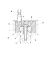
図4は、非共振型野圧電セラミックセンサにあって、非蓋構造の構成に係るものである。ここで凹状の金属製取付ケースa内に配設された振動感知部材bは、圧電素子cと重りdとを積層してなり、振動感知部材bに形成した中心孔eに取付螺子fを挿通して取付ケースaの底部に形成した螺子孔kに螺合し、かつ取付螺子fの頭部と、重りdとの間で、管状出力端子gの下端を挟持し、これにより出力端子gの接続端部を取付ケースa外に突出し、さらに、金属製取付ケースa内に封止樹脂を注入してなる。
【0006】
しかるにかかる構成にあっては、取付螺子fと、出力端子gとの絶縁処理が問題となり、このため出力端子gと取付螺子fの螺子頭との間に絶縁板hを介挿し、さらに振動感知部材bの中心孔e内で、取付螺子fの周囲に絶縁チューブiを挿入し、これにより圧電素子cの表裏電極の短絡を阻止するようにしている。このため、従来の蓋構造よりも、無蓋構造とすることにより部品点数が少なくなったものの、かかる絶縁処理のための部品を要して課題を残すものであった。本発明は、さらに部品点数が少なく、かつ組み付けが容易な無蓋構造の圧電ノックセンサを提供することを目的とするものである。
【0007】
【課題を解決するための手段】
本発明は、圧電素子を備える振動感知部材が弾性樹脂を充填した収容凹部内に保持された金属製取付ケースを有する圧電ノックセンサであって、前記取付ケースから外方へ突出する出力端子の下端部に、合成樹脂製取付螺子が形成され、該合成樹脂製取付螺子が、取付ケースに形成した螺子孔に螺合されるとともに、前記振動感知部材が該出力端子の周面に形成された保持突起と前記取付ケースとの間に挟持されることで前記収容凹部内に保持され、かつ前記圧電素子に形成された一方の電極を該出力端子と電気的に接続するようにしたことを特徴とする圧電ノックセンサである。
ここで、上述の構成は、振動感知部材が、圧電素子と重りとを積層してなる非共振型圧電ノックセンサのほかに、振動感知部材が、共振用金属薄板の一面に圧電素子を貼着してなる共振型圧電ノックセンサに適用され得る。
【0008】
かかる構成にあって、出力端子が取付ケースに絶縁状態で螺合されたものであるから、該取付螺子と出力端子との絶縁及び振動感知部材の中心孔内面と取付螺子との絶縁を要せず、絶縁板や絶縁チューブが不要となる。この様に絶縁状態で取付ケースに螺合するためには、出力端子の下端部に、合成樹脂製取付螺子をモールド成形により一体形成し、該合成樹脂製取付螺子を、振動感知部材に形成した中心孔に挿通して、ケースの底面に形成した螺子孔に螺合すると良い。また、振動感知部材の絶縁及び防水を弾性樹脂によって行っているため、無蓋構造とすることもできる。
【0009】
【発明の実施の形態】
添付図面について本発明の一実施例を説明する。
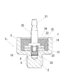
図1は本発明に係る内燃機関用の非共振型圧電ノックセンサS1 を示す。この圧電ノックセンサS1 は、凹状の金属製取付ケース1内に、振動感知部材10を配設してなるものである。ここで金属製取付ケース1の構造を説明すると、その周面を6角状とし、外底面中央に機関のシリンダ壁に螺合する取付ボルト2が突設されている。また、その内部には上方が開口する収納凹部3が形成されている。さらに、該収納凹部3の座底4には、取付ボルト2の中心線に沿って、螺子孔5が形成されている。
【0010】
この螺子孔5には、振動感知部材10が本発明の合成樹脂製取付螺子25により中心支持される。この振動感知部材10は、中心に挿通孔が形成された環状の圧電素子13の上面に同じく挿通孔が形成された重り14を積層することによって形成される中心孔16を螺子孔5と同心にして座底4上に配設され、上述のように合成樹脂製取付螺子25により保持される。
【0011】
次に、本発明の要部につき説明する。
図2で拡大して示すように、合成樹脂製取付螺子25は直杆状の出力端子20の下端に、モールド成形により一体的に配設されている。この出力端子20は、上端部を金属製取付ケース1から突出する接続端部21としているものであり、さらに下端側周面に径大の鍔状保持突部22が形成され、該保持突部22から下端側の周面に係合歯を備えた連結突部23が形成された直杆状をなすものである。そしてこの連結突部23には、合成樹脂製取付螺子25がモールド成形により一体的に形成される。この合成樹脂製取付螺子25は、PPS樹脂等の硬質樹脂からなり、その周面に螺子が形成される。
【0012】
そして上述のように、振動感知部材10の中心孔16から合成樹脂製取付螺子25を挿入して、螺子孔5に螺合緊締し、これにより、保持突部22を重り14を介して圧電素子13の上面電極と接続し、かつ圧電素子13の下面電極を座底4に接触して、ボディーアースする。このとき合成樹脂製取付螺子25により圧電素子13の内面は絶縁が確保され、かつ出力端子20がアース接続されることがない。
【0013】
かかる構成にあって、振動感知部材10を収納凹部3内に取付けた後に、該収納凹部3内に、シリコン等の封止樹脂26が充填される。そして、出力端子20の接続端部21のみが収納凹部3の開口から、上方へ突出することとなる。これにより振動感知部材10は収納凹部3内に封止され、圧電素子13の表裏面の電極は合成樹脂製取付螺子25及び封止樹脂26により絶縁的に保護されることとなる。
【0014】
かかる構成にあって、出力端子20に合成樹脂製取付螺子25を一体成形したものであるから、図4で示す先行技術の構成と異なり、絶縁板や絶縁チューブが不要となる。
【0015】
かかる構成にあって、この圧電ノックセンサS1 は、シリンダブロック等のノッキング振動が伝播する場所に取付ボルト2により螺着される。そして、該ノッキングが発生すると、合成樹脂製取付螺子25により中心保持された、振動感知部材10は、その慣性力により厚み方向の歪を生じ、該圧電素子13の表裏面の電極間に電位差が発生して、この圧電素子13の上面電極に接続された出力端子20の接続端部21から出力信号が取り出される。そして、この圧電ノックセンサS1 によりノッキング振動に伴う出力信号が取り出されることにより、該ノッキング振動が検出され、これにより燃料の点火時期を制御する等の手段で該ノッキング振動の防止対策が図られることとなる。
【0016】
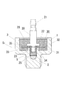
図3は本発明に係る内燃機関用の共振型圧電ノックセンサS2 を示す。ここで、図1,2と同一構成については、同一符号を付して説明を省略する。
この圧電ノックセンサS2 は、凹状の金属製取付ケース1内に、共振型の振動感知部材30を配設してなるものである。ここで金属製取付ケース1の該収納凹部3の座底4には、螺子孔5と同心状に環状座部34が形成され、該環状座部34上に振動感知部材30が配設される。
【0017】
この振動感知部材30は、共振用金属薄板31の上面に圧電素子32を貼着してなり、その下面を環状座部34により保持される。また金属薄板31,圧電素子32に夫々形成された挿通孔によって中心孔33が形成される。そして、保持突部22の下面に環状の座金35を配設し、保持突部22の下端側に一体的に形成された合成樹脂製取付螺子25を中心孔33に挿入して、螺子孔5に螺合し、これにより該振動感知部材30は座金35と環状座部34間で挟持される。この固着状態で、金属製取付ケース1には封止樹脂26が充填される。そして、出力端子20の接続端部21を封止樹脂26から外方へ突出している。
【0018】
ここで、封止樹脂26は、ノッキングの発生により振動を生じた場合に、振動感知部材30の振動を阻害しない程度の弾性を有するものとする。
かかる構成の共振型圧電ノックセンサS2 にあっても、図1の非共振型圧電ノックセンサS1 と同様に、絶縁材を要せず部品点数が減少することとなる。
【0019】
かかる構成にあって、この内燃機関用共振型圧電ノックセンサS2 は、シリンダブロック等のノッキング振動が伝播する場所に取付ボルト2により螺着される。そして、該ノッキングが発生すると、合成樹脂製取付螺子25により中心保持され、かつ封止樹脂26により阻害しない程度に封止された振動感知部材30は、金属薄板31が上下に湾曲し、該圧電素子32の表裏面の電極間に電位差を生じ、この圧電素子32の上面電極に接続された出力端子20から出力信号が取り出される。このとき、振動感知部材30の共振周波数とノッキング周波数とはあらかじめ一致するように設定され、ノッキングが発生すると、座金35及び環状座部34の周縁を振動節としたベンディング振動モードにより共振し、圧電素子32から最大出力が発生する。そして、この内燃機関用共振型圧電ノックセンサS2 によりノッキング振動に伴う出力信号が取り出されることにより、該ノッキング振動が検出され、これにより燃料の点火時期を制御する等の手段で該ノッキング振動の防止対策が図られることとなる。
【0020】
【発明の効果】
本発明の圧電ノックセンサS1 ,S2 は、上述したように、振動感知部材を中心位置で金属製取付ケースの上面が開口する収納凹部の底面に支持し、該収納凹部内に封止樹脂を充填して非蓋構造としたものにおいて、取付ケースから外方へ突出する出力端子の下端部に、合成樹脂製取付螺子をモールド成形により一体形成し、該合成樹脂製取付螺子により振動感知部材を中心支持し、圧電素子の一側電極を出力端子と電気的に接続するようにしたものであるから、合成樹脂製取付螺子により、所要の絶縁が施され、絶縁板や絶縁チューブ等の絶縁材が不要となる。このため、部品点数を可及的に少なくでき、組み付け容易で低廉な圧電ノックセンサを提供し得る優れた効果がある。
【図面の簡単な説明】
【図1】本発明に係る非共振型圧電ノックセンサS1 の縦断側面図である。
【図2】下端に合成樹脂製取付螺子25が一体形成された出力端子20の拡大側面図である。
【図3】本発明に係る共振型圧電ノックセンサS2 の縦断側面図である。
【図4】先行技術に係る圧電共振型ノックセンサの縦断側面図である。
【符号の説明】
S1 ,S2 圧電共振型ノックセンサ
1 金属製取付ケース
5 螺子孔
10 振動感知部材
13 圧電素子
14 重り
16 中心孔
20 出力端子
21 接続端部
23 連結突部
25 合成樹脂製取付螺子
26 封止樹脂
30 振動感知部材
31 金属薄板
32 圧電素子
33 中心孔[0001]
BACKGROUND OF THE INVENTION
The present invention relates to a piezoelectric knock sensor used to detect the occurrence of knocking in a cylinder by being solidified to a cylinder or the like of an internal combustion engine.
[0002]
[Prior art]
Various types of piezoelectric knock sensors are proposed in which a vibration sensing member including a piezoelectric element is supported in the center on the bottom surface of a housing recess in which the upper surface of the metal mounting case opens. Yes. As this type of piezoelectric knock sensor, a non-resonant piezoelectric knock sensor including a vibration sensing member including an element formed by stacking a piezoelectric element and a weight, and an annular piezoelectric element is attached to one surface of a resonance metal thin plate. There is a resonance type piezoelectric knock sensor provided with a vibration sensing unit. The former non-resonant piezoelectric knock sensor generates a signal voltage between electrodes by causing displacement in the thickness direction corresponding to the knocking frequency by inertial force of the piezoelectric element due to the occurrence of knocking. Further, the latter resonance type piezoelectric knock sensor causes the piezoelectric element to vibrate well with the occurrence of knocking by matching the natural resonance frequency of the vibration sensing member with the frequency of the knocking vibration wave. The maximum output is generated.
[0003]
[Problems to be solved by the invention]
In this type of piezoelectric knock sensor, a vibration sensing member is supported at the center of the seating surface of a storage recess formed in a metal mounting case, and the upper opening of the storage recess is shielded by a connector that also serves as a lid. In general, the internal gap is sealed, and an electrode formed on the upper surface of the piezoelectric element is connected to a metal output terminal inserted through the center of the connector. By the way, in such a configuration, due to the looseness of the synthetic resin connector, the airtightness in the case is reduced, moisture or the like enters, and the output terminal inserted through the center of the synthetic resin connector, There is a problem that the electrodes of the piezoelectric element are connected by lead wires, and complicated insulation processing is required and the connecting means is complicated. Therefore, the present inventors filled a sealing resin into the housing recess in the case where the vibration sensing member including the piezoelectric element is supported on the bottom surface of the housing recess where the upper surface of the metal mounting case opens at the center position. Thus, a non-lid piezoelectric knock sensor in which a vibration sensing member is embedded in a sealing resin has been proposed.
[0004]
In such a configuration, a connector that also serves as a lid is not required for the lidless structure, and the structure is simplified because the insulation of the vibration sensing member is performed by filling the housing recess with sealing resin, In addition, since the connection end of the output terminal connected to the electrode of the piezoelectric element only has to be protruded from the sealing resin and an external electric circuit is connected to the connection end, there is an advantage that the connection means is also simplified. Moreover, sealing is ensured and each component is protected from moisture, oil, and the like.
[0005]
FIG. 4 is a non-resonant type field piezoelectric ceramic sensor, which relates to the structure of a non-lid structure. Here, the vibration sensing member b disposed in the concave metal mounting case a is formed by laminating the piezoelectric element c and the weight d, and the mounting screw f is inserted into the center hole e formed in the vibration sensing member b. Then, the lower end of the tubular output terminal g is clamped between the head of the mounting screw f and the weight d, so that the lower end of the tubular output terminal g is clamped. The connecting end protrudes out of the mounting case a, and a sealing resin is injected into the metal mounting case a.
[0006]
Accordingly, in the configuration, the insulation treatment between the mounting screw f and the output terminal g becomes a problem. For this reason, an insulating plate h is inserted between the output terminal g and the screw head of the mounting screw f, and vibration detection is further performed. An insulating tube i is inserted around the mounting screw f in the center hole e of the member b, thereby preventing a short circuit between the front and back electrodes of the piezoelectric element c. For this reason, although the number of parts is reduced by adopting a lidless structure as compared with the conventional lid structure, a part for such an insulation process is required and a problem remains. It is an object of the present invention to provide a piezoelectric knock sensor having a lidless structure that has a smaller number of parts and can be easily assembled.
[0007]
[Means for Solving the Problems]
The present invention is a piezoelectric knock sensor having a metal mounting case in which a vibration sensing member including a piezoelectric element is held in an accommodation recess filled with an elastic resin, and a lower end of an output terminal protruding outward from the mounting case A synthetic resin mounting screw is formed on the portion, the synthetic resin mounting screw is screwed into a screw hole formed in the mounting case, and the vibration sensing member is formed on the peripheral surface of the output terminal. The electrode is held in the housing recess by being sandwiched between a protrusion and the mounting case, and one electrode formed on the piezoelectric element is electrically connected to the output terminal. This is a piezoelectric knock sensor.
Here, in the above configuration, in addition to the non-resonant piezoelectric knock sensor in which the vibration sensing member is formed by laminating the piezoelectric element and the weight, the vibration sensing member has a piezoelectric element attached to one surface of the resonance metal thin plate. The present invention can be applied to a resonance type piezoelectric knock sensor.
[0008]
In such a configuration, since the output terminal is screwed into the mounting case in an insulated state, it is necessary to insulate the mounting screw from the output terminal and to insulate the inner surface of the center hole of the vibration sensing member from the mounting screw. Therefore, an insulating plate and an insulating tube are not required. To screwed to the mounting case in an insulated state in this manner, the lower end of the output terminal, a synthetic resin mounting screw integrally formed by molding, the synthetic resin mounting screws, formed in the vibration detecting member It may be inserted into the center hole and screwed into a screw hole formed in the bottom surface of the case. In addition, since the vibration sensing member is insulated and waterproofed by an elastic resin, a lidless structure can be provided.
[0009]
DETAILED DESCRIPTION OF THE INVENTION
An embodiment of the present invention will be described with reference to the accompanying drawings.
FIG. 1 shows a non-resonant piezoelectric knock sensor S1 for an internal combustion engine according to the present invention. This piezoelectric knock sensor S1 is formed by disposing a vibration sensing
[0010]
The vibration sensing
[0011]
Next, the main part of the present invention will be described.
As shown in FIG. 2 in an enlarged manner, the synthetic
[0012]
Then, as described above, the synthetic
[0013]
In this configuration, after the
[0014]
In such a configuration, since the synthetic
[0015]
In this configuration, the piezoelectric knock sensor S1 is screwed by the mounting
[0016]
FIG. 3 shows a resonance type piezoelectric knock sensor S2 for an internal combustion engine according to the present invention. Here, the same components as those of FIGS.
This piezoelectric knock sensor S2 is formed by disposing a resonance type
[0017]
The
[0018]
Here, it is assumed that the sealing
Even in the resonance type piezoelectric knock sensor S2 having such a configuration, like the non-resonance type piezoelectric knock sensor S1 of FIG. 1, an insulating material is not required and the number of parts is reduced.
[0019]
In this configuration, the resonance type piezoelectric knock sensor S2 for an internal combustion engine is screwed by the mounting
[0020]
【The invention's effect】
As described above, the piezoelectric knock sensors S1 and S2 of the present invention support the vibration sensing member on the bottom surface of the housing recess where the top surface of the metal mounting case opens at the center position, and fill the housing recess with sealing resin. In the non-cover structure, a synthetic resin mounting screw is integrally formed by molding at the lower end portion of the output terminal protruding outward from the mounting case, and the vibration detection member is centered by the synthetic resin mounting screw. Since one side electrode of the piezoelectric element is electrically connected to the output terminal, the required insulation is provided by a synthetic resin mounting screw, and an insulating material such as an insulating plate or an insulating tube is provided. It becomes unnecessary. For this reason, the number of parts can be reduced as much as possible, and there is an excellent effect that an inexpensive and easy-to-assemble piezoelectric knock sensor can be provided.
[Brief description of the drawings]
FIG. 1 is a longitudinal side view of a non-resonant piezoelectric knock sensor S1 according to the present invention.
FIG. 2 is an enlarged side view of the
FIG. 3 is a longitudinal side view of a resonance type piezoelectric knock sensor S2 according to the present invention.
FIG. 4 is a longitudinal side view of a piezoelectric resonance type knock sensor according to the prior art.
[Explanation of symbols]
S1, S2 Piezoelectric resonance
Claims (3)
前記取付ケースから外方へ突出する出力端子の下端部に、合成樹脂製取付螺子が形成され、該合成樹脂製取付螺子が、取付ケースに形成した螺子孔に螺合されるとともに、
前記振動感知部材が該出力端子の周面に形成された保持突起と前記取付ケースとの間に挟持されることで前記収容凹部内に保持され、かつ前記圧電素子に形成された一方の電極を該出力端子と電気的に接続するようにしたことを特徴とする圧電ノックセンサ。A piezoelectric knock sensor having a metal mounting case in which a vibration sensing member including a piezoelectric element is held in an accommodation recess filled with an elastic resin,
A synthetic resin mounting screw is formed at the lower end portion of the output terminal protruding outward from the mounting case , and the synthetic resin mounting screw is screwed into a screw hole formed in the mounting case .
The vibration sensing member is held between the holding projection formed on the peripheral surface of the output terminal and the mounting case, so that one electrode formed on the piezoelectric element is held in the housing recess. A piezoelectric knock sensor characterized by being electrically connected to the output terminal.
Priority Applications (1)
| Application Number | Priority Date | Filing Date | Title |
|---|---|---|---|
| JP2000046492A JP3657166B2 (en) | 2000-02-23 | 2000-02-23 | Piezoelectric knock sensor |
Applications Claiming Priority (1)
| Application Number | Priority Date | Filing Date | Title |
|---|---|---|---|
| JP2000046492A JP3657166B2 (en) | 2000-02-23 | 2000-02-23 | Piezoelectric knock sensor |
Publications (2)
| Publication Number | Publication Date |
|---|---|
| JP2001235362A JP2001235362A (en) | 2001-08-31 |
| JP3657166B2 true JP3657166B2 (en) | 2005-06-08 |
Family
ID=18568888
Family Applications (1)
| Application Number | Title | Priority Date | Filing Date |
|---|---|---|---|
| JP2000046492A Expired - Fee Related JP3657166B2 (en) | 2000-02-23 | 2000-02-23 | Piezoelectric knock sensor |
Country Status (1)
| Country | Link |
|---|---|
| JP (1) | JP3657166B2 (en) |
Families Citing this family (5)
| Publication number | Priority date | Publication date | Assignee | Title |
|---|---|---|---|---|
| JP5731747B2 (en) * | 2009-11-24 | 2015-06-10 | 日本特殊陶業株式会社 | Knocking sensor |
| DE102010037379B4 (en) * | 2010-09-07 | 2021-09-23 | Homa Pumpenfabrik Gmbh | Pump arrangement with integrated vibration measurement |
| CN103328944B (en) | 2011-02-24 | 2016-04-13 | 日本特殊陶业株式会社 | Detonation sensor |
| JP5314073B2 (en) * | 2011-04-08 | 2013-10-16 | 三菱電機株式会社 | Knock sensor for internal combustion engine |
| JP2020112355A (en) * | 2019-01-08 | 2020-07-27 | 三菱マテリアル株式会社 | Temperature sensor device and sensor system |
-
2000
- 2000-02-23 JP JP2000046492A patent/JP3657166B2/en not_active Expired - Fee Related
Also Published As
| Publication number | Publication date |
|---|---|
| JP2001235362A (en) | 2001-08-31 |
Similar Documents
| Publication | Publication Date | Title |
|---|---|---|
| JPH0624755Y2 (en) | Washer pressure sensor | |
| US6786078B2 (en) | Vibration pickup comprising a clamping sleeve | |
| JP3657166B2 (en) | Piezoelectric knock sensor | |
| CN105339768B (en) | knock sensor | |
| JP4378040B2 (en) | Spark plug and plug cap with built-in pressure sensor | |
| US4945755A (en) | Acceleration detector with parallel ground paths | |
| JPH05264324A (en) | Piezo-electric oil level sensor | |
| JP3905809B2 (en) | Non-resonant knock sensor | |
| JPH02659Y2 (en) | ||
| JPS6117288B2 (en) | ||
| JP2001235361A (en) | Piezoelectric resonance type knock sensor | |
| JP5129070B2 (en) | Knocking sensor | |
| JPH07902Y2 (en) | Vibration sensor | |
| JPH02658Y2 (en) | ||
| JP3720330B2 (en) | Knock sensor | |
| JP2732110B2 (en) | Non-resonant knock sensor | |
| JPH052034U (en) | Notting detector | |
| JPH07218331A (en) | Knocking detector of internal combustion engine for car nd production thereof | |
| JPS641615Y2 (en) | ||
| JP2550077Y2 (en) | Knock sensor for internal combustion engine | |
| JPS6032587Y2 (en) | Notking sensor | |
| JP3402504B2 (en) | Vibration sensor and manufacturing method thereof | |
| JPH07253357A (en) | Vibration sensor and manufacture therefor | |
| JPS641613Y2 (en) | ||
| JPS641614Y2 (en) |
Legal Events
| Date | Code | Title | Description |
|---|---|---|---|
| A977 | Report on retrieval |
Free format text: JAPANESE INTERMEDIATE CODE: A971007 Effective date: 20041104 |
|
| A131 | Notification of reasons for refusal |
Free format text: JAPANESE INTERMEDIATE CODE: A131 Effective date: 20041126 |
|
| A521 | Request for written amendment filed |
Free format text: JAPANESE INTERMEDIATE CODE: A523 Effective date: 20050118 |
|
| TRDD | Decision of grant or rejection written | ||
| A01 | Written decision to grant a patent or to grant a registration (utility model) |
Free format text: JAPANESE INTERMEDIATE CODE: A01 Effective date: 20050209 |
|
| A61 | First payment of annual fees (during grant procedure) |
Free format text: JAPANESE INTERMEDIATE CODE: A61 Effective date: 20050308 |
|
| R150 | Certificate of patent or registration of utility model |
Free format text: JAPANESE INTERMEDIATE CODE: R150 |
|
| FPAY | Renewal fee payment (event date is renewal date of database) |
Free format text: PAYMENT UNTIL: 20090318 Year of fee payment: 4 |
|
| FPAY | Renewal fee payment (event date is renewal date of database) |
Free format text: PAYMENT UNTIL: 20090318 Year of fee payment: 4 |
|
| FPAY | Renewal fee payment (event date is renewal date of database) |
Free format text: PAYMENT UNTIL: 20100318 Year of fee payment: 5 |
|
| FPAY | Renewal fee payment (event date is renewal date of database) |
Free format text: PAYMENT UNTIL: 20100318 Year of fee payment: 5 |
|
| LAPS | Cancellation because of no payment of annual fees |