JP3656252B2 - Differential interference microscope - Google Patents
Differential interference microscope Download PDFInfo
- Publication number
- JP3656252B2 JP3656252B2 JP19671793A JP19671793A JP3656252B2 JP 3656252 B2 JP3656252 B2 JP 3656252B2 JP 19671793 A JP19671793 A JP 19671793A JP 19671793 A JP19671793 A JP 19671793A JP 3656252 B2 JP3656252 B2 JP 3656252B2
- Authority
- JP
- Japan
- Prior art keywords
- light
- test object
- image
- objective lens
- birefringent element
- Prior art date
- Legal status (The legal status is an assumption and is not a legal conclusion. Google has not performed a legal analysis and makes no representation as to the accuracy of the status listed.)
- Expired - Lifetime
Links
- 230000003287 optical effect Effects 0.000 claims description 24
- 238000003384 imaging method Methods 0.000 claims description 7
- 230000002708 enhancing effect Effects 0.000 claims description 3
- 230000002452 interceptive effect Effects 0.000 claims description 2
- 230000010287 polarization Effects 0.000 claims description 2
- 210000001747 pupil Anatomy 0.000 description 8
- 238000010586 diagram Methods 0.000 description 7
- 238000005286 illumination Methods 0.000 description 5
- 230000001965 increasing effect Effects 0.000 description 5
- 230000000694 effects Effects 0.000 description 4
- 230000005540 biological transmission Effects 0.000 description 3
- 238000000926 separation method Methods 0.000 description 3
- 239000013078 crystal Substances 0.000 description 2
- 230000004907 flux Effects 0.000 description 1
- 230000001771 impaired effect Effects 0.000 description 1
- 239000000463 material Substances 0.000 description 1
Images


Classifications
-
- G—PHYSICS
- G02—OPTICS
- G02B—OPTICAL ELEMENTS, SYSTEMS OR APPARATUS
- G02B21/00—Microscopes
- G02B21/06—Means for illuminating specimens
- G02B21/08—Condensers
- G02B21/14—Condensers affording illumination for phase-contrast observation
-
- G—PHYSICS
- G02—OPTICS
- G02B—OPTICAL ELEMENTS, SYSTEMS OR APPARATUS
- G02B21/00—Microscopes
Landscapes
- Physics & Mathematics (AREA)
- Chemical & Material Sciences (AREA)
- Analytical Chemistry (AREA)
- General Physics & Mathematics (AREA)
- Optics & Photonics (AREA)
- Microscoopes, Condenser (AREA)
- Lenses (AREA)
- Polarising Elements (AREA)
Description
【0001】
【産業上の利用分野】
本発明は、例えば生物標本の観察等に用いられる微分干渉顕微鏡に関するものである。
【0002】
【従来の技術】
従来の微分干渉顕微鏡には、例えば図5に示すような透過照明型のものがあった。この微分干渉顕微鏡は、図5(a)において、光源Sからの光をレンズL1 、レンズL2 およびコンデンサレンズL3 によって標本Mをケーラー照明し、この標本Mの透過光が対物レンズL4 を介して形成する拡大像Yを接眼レンズL5 を介して肉眼で観察するという顕微鏡光学系に微分干渉部材、即ち偏光子P、検光子A、ウオラストンプリズムW1 、ウオラストンプリズムW2 を組み込んだものである。
【0003】
ウオラストンプリズムW1 はコンデンサレンズL3 の入射瞳位置に、ウオラストンプリズムW2 は対物レンズL4 の射出瞳位置に各々配置され、偏光子PはウオラストンプリズムW1 の手前(光源S側)に、検光子AはウオラストンプリズムW2 の後ろ(接眼レンズL5 側)に配置されている。
【0004】
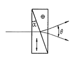
ウオラストンプリズムは、図6に示すように、それぞれの光学軸方向が互いに直交する状態で切り出された2つの直角プリズムを接合してなるものであり、ここでは一方が紙面に平行な光軸方向(矢印)で他方が紙面に垂直な光軸方向(+印)となっている。このプリズムは、入射光線を互いに直交する振動面を持つ2つの直線偏光に分離する。この時2つの光線は、直角プリズムの頂角αで決定される偏角θ=2(ne −n0 )tan αで分離する。ここで、ne は異常光線に対するウオラストンプリズムの屈折率、n0 は常光線に対するウオラストンプリズムの屈折率である。
【0005】
上記のような構成において、図5(b)に示すように、光源Sからの光は偏光子Pによって矢印方向の直線偏光が取り出され、この直線偏光は、ウオラストンプリズムW1 によって互いに直交する2つの直線偏光に偏角θをもって分離される。通常ウオラストンプリズムは、使用される対物レンズに応じて選択され、対物レンズを取り替える際に一緒に取り替えられる。
【0006】
この分離された2光線はコンデンサレンズL3 に入射するが、このときウオラストンプリズムW1 がコンデンサレンズL3 の前側焦点面に位置すれば、2つの直線偏光はコンデンサレンズL3 の焦点距離fc と角度θによって決まる量(シアー量)S=fc ・tanθだけ離れた平行光線となって標本Mを照射する。
【0007】
標本Mを透過した2光線は、対物レンズL4 によって対物レンズL4 の後ろ側焦点面で交わり、ここに配置されたウオラストンプリズムW2 よって1つとなり、同一光路上を進む。さらに検光子Aを透過することによってこれら2光線の逆位相成分が取り出され、互いに干渉し合うようになる。
【0008】
即ち、標本M内を通過することによって2つの光線に光路差が生じなければ、2光線は干渉し打ち消し合て暗くなるが、逆に光路差が生じていれば明るく見える。微分干渉顕微鏡はこの原理を利用したものであり、標本Mが無色透明であっても、標本M内の屈折率や厚さの差に応じて2光線に光路差が生じていれば、標本Mを明暗の差で観察することが可能となる。
【0009】
このような微分干渉顕微鏡では、肉眼による観察が主であったため、像Yにある程度のコントラストが必要であった。このコントラストはシアー量Sの大きさで決定される。コントラストを上げたい時にはシアー量Sを大きくすれば良い。
【0010】
例えば、図7(a)に示すような標本M内に屈折率が高い部分M’が存在する場合を考えてみると、光線の同一位相面を線分abで表すと、入射光abは標本Mを通過後a’b’となって進む。この時シアー量Sだけ離れた2つの光線は図7(b)に示すごとく重なりあうが、2光線の光路差Δによって生じる明暗によってコントラストが得られる。図からも明らかなように、シアー量Sが小さいと2光線の光路差Δが小さくコントラストが低くなる。シアー量Sを大きく取ればコントラストは上り、わずかな傾斜であっても明暗のコントラストが生じる。
【0011】
【発明が解決しようとする課題】
しかしながら、上記の如き従来の微分干渉顕微鏡では、シアー量Sを大きく取ってコントラストを上げようとすると、対物レンズL4 の分解能をある程度犠牲にしなければならなかった。
【0012】
例えば、シアー量Sが対物レンズの分解能δ(δ=0.61×λ/N.A.)を越えた時には標本Mの像Yは2重になって見えてしまう。さらに、シアー量Sをそれほど大きくなく対物レンズL4 の分解能δ以下としても、分解能δ近くに設定した場合、このシアー量Sの方向に像が伸びる現象も起こる。
【0013】
これによって本来対物レンズの性能としては分解できるはずの微細部分がつぶれて見えるという問題もあった。従って従来は、対物レンズの分解能をできるだけ損なわないようにするためにはシアー量Sを小さくすることが望まれるが、比較的高いコントラストを得るためには、シアー量Sをδ/2程度が限界であった。
【0014】
本発明は、上記問題を解消し、コントラストを上げても対物レンズの分解能をより活かすことのできる微分干渉顕微鏡を得ることを目的とする。
【0015】
【課題を解決するための手段】
上記目的を達成するため、請求項1に記載の発明に係る微分干渉顕微鏡装置では、光源と、該光源からの光を集光して被検物を照明するコンデンサレンズと、前記被検物を介した前記コンデンサレンズからの光を集光して前記被検物の像を形成する対物レンズと、前記像を観察するための観察手段とを有し、前記光源と前記コンデンサレンズとの間に、前記光源側から順に、前記光源からの光束を所定の偏光光とする第1の偏光手段と、前記偏光光を常光線と異常光線との2光線に分離する第1の複屈折素子とを配置すると共に、 前記対物レンズと前記観察手段との間に、前記被検物から順に、前記被検物を介した前記2光線を同一光路上に導く第2の複屈折素子と、前記同一光路上に導かれた2光線を干渉させる第2の偏光手段とを配置した微分干渉顕微鏡において、前記観察手段は、前記被検物の像を光電的に検出する撮像手段と、該撮像手段に検出された前記被検物の像のコントラストを強調するコントラスト強調手段とを有し、さらに、前記対物レンズの分解能をδとしたとき、前記常光線と前記異常光線とのシアー量Sが以下の条件(1) 式を満たすものとした。
δ/20≦S≦2δ/5 …(1) 式
【0016】
また、請求項2に記載の発明に係る微分干渉顕微鏡では、請求項1に記載の微分干渉顕微鏡において、前記コンデンサレンズが前記被検物からの反射光を集光する対物レンズとして共用されると共に、前記第1の複屈折素子が前記第2の複屈折素子として共用される構成とし、前記第1の偏光手段と前記第1の複屈折素子との間に、前記コンデンサレンズと前記第1の複屈折素子とを介した前記被検物からの反射光を前記第2の偏光手段へ導く光路分割手段を備えた。
【0017】
【作用】
本発明は、光源側からの光束を第1の偏光手段で所定の偏光光とし、該偏光光をウオラストンプリズム等の複屈折素子によって常光線と異常光線との2光線に分離し、コンデンサレンズで集光し被検物を照明させ、被検物を介した2光線を第2の複屈折素子により同一光路上に導き、さらに第2の偏光手段によって互いに干渉させる、微分干渉像を得る微分干渉顕微鏡であり、この像を観察するための観察手段において、撮像手段によって被検物の像を光電的に検出し、コントラスト強調手段によって撮像手段に検出された被検物の像のコントラストを強調してモニタ等の表示手段の画面上に表示するものである。
【0018】
請求項1に記載の本発明においては、上記構成により、得られる微分干渉像のコントラストが低くてもこれを強調することができるので、コントラスを低く、即ち常光線と異常光線との被検面上でのシアー量S=fc ・tanθ(fc :コンデンサレンズの焦点距離、θ:第1の結晶光学素子による常光線と異常光線との分離角)が小さくなるよう光学系を設定することができる。
【0019】
従って、本発明によれば、被検物の像が2重に見えたり微細部分がつぶれて見えたり等、像の品質が損なわれることがなく、対物レンズの分解能が活かされたまま、対物レンズによる像を極めてシャープな微分干渉像として捕らえることがでるとともに、最終的にはにコントラストの高い観察像を得ることができる。
【0020】
なお、本発明においては、対物レンズの分解能をδとしたときシアー量Sを前記条件式(1) を満たすものとした。この条件式の下限を越えた場合、シアー量Sが小さ過ぎて2光線の干渉効果が非常に小さく、コントラストの強調を施しても観察に十分な高いコントラストを得ることができない。また、このようにシアー量Sを非常に小さくするような、即ち常光線と異常光線の分離角θが小さい結晶光学素子(ウオラストンプリズム)を形成することが困難である。
【0021】
一方、上限を越えた場合は、従来の微分干渉顕微鏡と同様に対物レンズの分解能を損なう恐れがあり、分解能限界付近で被検物を観察する際に不利である。本発明はシアー量Sを条件式(1) の範囲内に限定することにより、常に対物レンズの分解能を活かしつつ高いコントラストの観察像が得られる。なお、対物レンズの分解能をより高めながら、高いコントラストのもとで被検物の像を観察するためには、条件式(1) に示したシアー量Sに関する範囲をさらにδ/20≦S≦2δ/5とすることが望ましい。
【0022】
さらに、請求項2に記載の本発明は、コンデンサレンズを被検物からの反射光を集光する対物レンズとして共用し、且つ第1の複屈折素子を第2の複屈折素子として共用する構成とし、第1の偏光手段と複屈折素子との間に、コンデンサレンズと第1の複屈折素子とを介した被検物からの反射光を第2の偏光手段へ導く光路分割手段を設けることによって反射型の微分干渉顕微鏡とするものである。
【0023】
このような構成においては、第1の複屈折素子で分離した2光線をコンデンサレンズによって被検物に照射し、被検物からの反射光を逆行させ、再びコンデンサレンズを介して集光し、さらに第1の複屈折素子で2光線を同一光路上に導いた後、光路分割手段によって第2の偏光素子へ導き、これによって2光線を互いに干渉させ被検物の微分干渉像を得ることができる。
【0024】
この像は、請求項1に記載の発明と同様に、観察手段において、撮像手段によって光電的に検され、コントラスト強調手段によって像のコントラストが強調される。従って、本発明によれば、常に対物レンズの分解能を活かしつつ高いコントラストの観察像が得られる反射型微分干渉顕微鏡をも実現できる。
【0025】
【実施例】
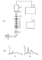
以下に、本発明の実施例を説明する。図1(a)に、本発明の第1の実施例として透過照明型の微分干渉顕微鏡装置を示す。本実施例は、光源1からの光をレンズ2、レンズ3、コンデンサレンズ6により標本7を照明し、対物レンズ8によって拡大像11を得るという構成の顕微鏡に、微分干渉用部材である偏光子4、検光子10、ウオラストンプリズム5、ウオラストンプリズム9を組み込んだものである。
【0026】
ウオラストンプリズム5はコンデンサレンズ6の入射瞳位置に、ウオラストンプリズム9は対物レンズ8の射出瞳位置に各々配置され、偏光子4はウオラストンプリズム5の手前(光源1側)に、検光子10はウオラストンプリズム9の後ろに配置されている。
【0027】
上記のような構成において、光源1からの光は偏光子4によって直線偏光が取り出され、この直線偏光は、ウオラストンプリズム5によって互いに直交する2つの直線偏光に偏角θをもって分離される。
【0028】
この分離された2光線はコンデンサレンズ6に入射し、シアー量Sだけ離れた平行光線となって標本7を照射する。標本7を透過した2光線は、対物レンズ8によって対物レンズ8の後ろ側焦点面で交わり、ここに配置されたウオラストンプリズム9よって1つとなり、同一光路上を進む。さらに検光子10を透過することによってこれら2光線の逆位相成分が取り出され、互いに干渉し合うようになり、像面11に微分干渉像を形成する。
【0029】
ここで、ウオラストンプリズム5およびウオラストンプリズム9は、標本7におけるシアー量Sが対物レンズ8の分解能δに対してδ/20≦S<δ/2の範囲内になるよう設定されている。これにより、像面11における微分干渉像は、シアー量Sが従来のものより極端に小さいため、像としては極めてシャープなものではあるがコントラストは低く、肉眼や普通のビデオカメラ等では捕らえることができない。
【0030】
そこで、本実施例においては、このコントラストを増強するためのビデオエンハンスメントを行う回路13を、像面11の像を光電的に検出するCCDや撮像管等の撮像手段12とモニタ14との間に設置した。
【0031】
本実施例によるコントラスト増強の例を図1(b)に示す。なお、簡単のためコントラスト強度は横軸に位置x、縦軸に強度Iの一次元で表している。ここでは撮像手段12からの入力信号Si を単純に増幅しモニタ14上に信号So として出力するものである。入力信号Si のコントラストが、従来の微分干渉顕微鏡における肉眼での観察可能な閾値以下の弱いものであっても、モニタ14上では十分観察可能なコントラストの出力So となっている。
【0032】
以上のような構成の本実施例の微分干渉顕微鏡において、シアー量Sをδ/5およびδ/10(δ:対物レンズ8の分解能)に設定し、標本の観察を行って見たところ、いずれの場合も、シャープな観察像が得られ、従来の微分干渉顕微鏡において肉眼で見る以上にコントラストの強い迫力ある像が見られた。
【0033】
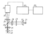
次に、本発明の第2の実施例として、反射型(落射照明)の微分干渉顕微鏡を図2に示す。本実施例は、光源21からの光をコレクタンズ22によって平行光束とした後、レンズ24にて対物レンズ27の瞳面に結像させ、対物レンズ27をによって標本面28を照明させ、標本面28からの反射光を再び対物レンズ27を通過させることによって像30を得るという構成の反射型顕微鏡に、微分干渉用部材である偏光子23、検光子29、ウオラストンプリズム26を組み込んだものである。
【0034】
ウオラストンプリズム26は、対物レンズ27の瞳面に配置され、第1の実施例と同様にシアー量Sが前記条件式(1) を満たすよう設定されている。このような構成において、光源21からの光は偏光子23によって直線偏光が取り出され、この直線偏光は、レンズ24、ハーフミラー25を介してウオラストンプリズム26によって互いに直交する2つの直線偏光に分離される。
【0035】
この分離された2光線は対物レンズ(コンデンサレンズ)27に入射し、シアー量Sだけ離れた平行光線となって標本面28を照射する。標本面28で反射された2光線は、再び対物レンズ27を通過し、対物レンズ27の後ろ側焦点面で交わり、ここに配置されたウオラストンプリズム26よって1つとなり、同一光路上を進む。さらにハーフミラー25を透過し検光子29を透過することによってこれら2光線の逆位相成分が取り出され、互いに干渉し合うようになり、像面30に微分干渉像を形成する。
【0036】
像面30の像は、第1の実施例と同様に、CCDや撮像管等の撮像手段31によって光電的に検出され、回路32でコントラストが強調された後、モニタ33の画面上に表示される。この表示画像は、シャープでコントラストの強いものである。
【0037】
なお、以上の実施例においては、対物レンズを有限系とし、第2の複屈折素子と第2の偏光手段とを対物レンズと像面との間に配置する構成を示したが、本発明はこれに限るものではない。例えば、図3(a)に示す如く、以上の実施例と同様に対物レンズ8を有限系の構成とし、標本7と対物レンズ8との間に第2の複屈折素子9を配置すると共に、対物レンズ8と像面11との間に第2の偏光手段10を配置しても良い。この場合、第1の複屈折素子5はコンデンサーレンズ6と標本7との間に配置されると共に第1の偏光手段4はコンデンサーレンズ6の光源側に(レンズ3とコンデンサーレンズ6との間)に配置される。
【0038】
また、図3(b)に示す如く、図3(a)に示した対物レンズ8をレンズ81、レンズ82の2群系として、各レンズ間を平行系(無限遠系)とする構成とし、その平行光束中に、標本7側から順に、第2の複屈折素子9と第2の偏光手段10とを配置しても良い。この場合、コンデンサーレンズ6は、対物レンズ8と同様に、レンズ61、レンズ62の2群系として各レンズ間を平行系(無限遠系)とする構成とし、第1の複屈折素子5と第1の偏光手段4とは、標本7側から順にそれぞれ平行光束中に配置される。
【0039】
なお、図3(a)及び(b)には、透過照明型の微分干渉顕微鏡の例を示したが、コンデンサーレンズ6と対物レンズ8とを共用させ、複屈折素子5、複屈折素子9と、偏光手段4、偏光手段10とを各々共用させて図2に示した如き反射照明型の微分干渉顕微鏡としても良い。
【0040】
また、本実施例では、複屈折素子としてウオラストンプリズムを用いる場合を示したが、本発明はこれに限るものではなく、第1の偏光手段で取り出された直線偏光を互いに直交する2つの直線偏光に所定の偏角で分離できるものであれば良い。例えば、対物レンズが複数のレンズ群で構成される場合など、焦点位置が対物レンズ中に存在することがある。
【0041】
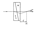
この時、焦点面にウオラストンプリズムを配置することはできいないので、図4に示す様なノマルスキープリズム(変形ウオラストンプリズム)を用いることができる。これは、プリズムと距離dだけ離れた位置で2光線を分離するものであるので、分離点Hが対物レンズの瞳位置となるよう設定すれば、ウオラストンプリズムが瞳位置にある場合と同様の作用が得られる。
【0042】
【発明の効果】
以上説明したとおり、本発明によれば、対物レンズの分解能を活かしたままコントラストの強い被検物の観察像を得ることができる。従って、例え無色透明な標本であっても、その屈折率や厚さの差に応じて極めてシャープな像がコントラスト良く観察することができるという効果がある。
【図面の簡単な説明】
【図1】本発明の第1の実施例による微分干渉顕微鏡の概略構成図である。
【図2】本発明の第2の実施例による微分干渉顕微鏡の概略構成図である。
【図3】第1、第2の実施例と異なる対物レンズ、偏光手段、複屈折素子の配置を示す構成図である。
【図4】複屈折素子として使用可能なノマルスキープリズムを説明する模式図である。
【図5】従来の微分干渉顕微鏡を示す概略構成図である。
【図6】実施例で複屈折素子として使用するウオラストンプリズムを説明する模式図である。
【図7】常光線と異常光線による標本M面上でのシアー量を示す模式図である。
【符号の説明】
1,21,S:光源
4,23,P:偏光子
6,27,61,62,L3 :コンデンサレンズ
5,9,26,W1 ,W2 :ウオラストンプリズム
7,28,M:標本
8,27,81,82,L4 :対物レンズ
10,29,A:検光子
11,30,Y:像面
12,31:撮像装置
13,32:(コントラスト強調)回路
14,33:モニタ[0001]
[Industrial application fields]
The present invention relates to a differential interference microscope used for observation of a biological specimen, for example.
[0002]
[Prior art]
A conventional differential interference microscope includes a transmission illumination type as shown in FIG. In the differential interference microscope, in FIG. 5A, the sample M is Koehler-illuminated with the light from the light source S by the lens L 1 , the lens L 2 and the condenser lens L 3 , and the transmitted light of the sample M is reflected by the objective lens L 4. A differential interference member, that is, a polarizer P, an analyzer A, a Wollaston prism W 1 , a Wollaston prism W 1 , and a microscope optical system for observing the magnified image Y formed through the eye with the naked eye through the eyepiece L 5. 2 is incorporated.
[0003]
The Wollaston prism W 1 is disposed at the entrance pupil position of the condenser lens L 3 , the Wollaston prism W 2 is disposed at the exit pupil position of the objective lens L 4 , and the polarizer P is in front of the Wollaston prism W 1 ( On the light source S side, the analyzer A is arranged behind the Wollaston prism W 2 (on the eyepiece L 5 side).
[0004]
As shown in FIG. 6, the Wollaston prism is formed by joining two right-angle prisms cut out in a state where their optical axis directions are orthogonal to each other. Here, one of the optical axes is parallel to the paper surface. The direction (arrow) and the other is the optical axis direction (+) perpendicular to the paper surface. This prism separates incident light rays into two linearly polarized light having vibration planes orthogonal to each other. In this case the two beams are polarized angle theta = 2, which is determined by alpha apex angle of the rectangular prism (n e -n 0) separated by tan alpha. Here, n e is the refractive index of the Wollaston prism for the extraordinary ray, n 0 is the refractive index of the Wollaston prism for ordinary ray.
[0005]
In the configuration as described above, as shown in FIG. 5B, light from the light source S is linearly polarized in the direction of the arrow by the polarizer P, and the linearly polarized light is orthogonal to each other by the Wollaston prism W 1 . Are separated with a declination angle θ. Typically, the Wollaston prism is selected according to the objective lens used and is replaced together when the objective lens is replaced.
[0006]
The two separated light beams are incident on the condenser lens L 3. At this time, if the Wollaston prism W 1 is positioned on the front focal plane of the condenser lens L 3 , the two linearly polarized lights are the focal length of the condenser lens L 3 . An amount (shear amount) determined by f c and angle θ (shear amount) S = f c · tan θ becomes parallel light rays that are separated from each other, and the sample M is irradiated.
[0007]
The two light beams that have passed through the sample M intersect at the back focal plane of the objective lens L 4 by the objective lens L 4 , become one by the Wollaston prism W 2 disposed here, and travel on the same optical path. Further, by passing through the analyzer A, the anti-phase components of these two rays are extracted and interfere with each other.
[0008]
In other words, if there is no optical path difference between the two light beams by passing through the sample M, the two light beams interfere and cancel each other out, but on the contrary, if there is an optical path difference, it looks bright. The differential interference microscope uses this principle. Even if the sample M is colorless and transparent, if the optical path difference occurs between the two rays according to the difference in refractive index and thickness in the sample M, the sample M Can be observed with a difference between light and dark.
[0009]
In such a differential interference microscope, observation with the naked eye was mainly used, and thus a certain amount of contrast was necessary for the image Y. This contrast is determined by the size of the shear amount S. When it is desired to increase the contrast, the shear amount S may be increased.
[0010]
For example, when considering a case where a portion M ′ having a high refractive index exists in the sample M as shown in FIG. 7A, when the same phase plane of the light beam is represented by a line segment ab, the incident light ab is After passing M, proceed as a'b '. At this time, two light beams separated by the shear amount S overlap as shown in FIG. 7B, but contrast is obtained by light and dark caused by the optical path difference Δ between the two light beams. As is apparent from the figure, when the shear amount S is small, the optical path difference Δ between the two rays is small and the contrast is low. If the shear amount S is increased, the contrast will increase, and a contrast of light and dark will occur even with a slight inclination.
[0011]
[Problems to be solved by the invention]
However, in the conventional differential interference microscope as described above, in order to increase the contrast by increasing the shear amount S, the resolution of the objective lens L 4 has to be sacrificed to some extent.
[0012]
For example, when the shear amount S exceeds the resolution δ (δ = 0.61 × λ / NA) of the objective lens, the image Y of the sample M appears to be doubled. Furthermore, even if the shear amount S is not so large and is less than or equal to the resolution δ of the objective lens L 4 , when the resolution is set close to δ, the phenomenon that the image extends in the direction of the shear amount S also occurs.
[0013]
As a result, there was also a problem that the fine parts that should be able to be decomposed appear to be crushed as the performance of the objective lens. Therefore, conventionally, it is desirable to reduce the shear amount S in order to minimize the resolution of the objective lens. However, in order to obtain a relatively high contrast, the shear amount S is limited to about δ / 2. Met.
[0014]
An object of the present invention is to obtain a differential interference microscope that can solve the above-described problems and can make better use of the resolution of the objective lens even when the contrast is increased.
[0015]
[Means for Solving the Problems]
In order to achieve the above object, in the differential interference microscope apparatus according to the first aspect of the present invention, a light source, a condenser lens for condensing light from the light source to illuminate the test object, and the test object are provided. An objective lens for condensing the light from the condenser lens through which an image of the test object is formed, and observation means for observing the image, and between the light source and the condenser lens , In order from the light source side, a first polarization unit that makes a light beam from the light source a predetermined polarized light, and a first birefringent element that separates the polarized light into two rays of an ordinary ray and an extraordinary ray A second birefringent element that guides the two light beams through the test object on the same optical path in order from the test object between the objective lens and the observation means, and the same light And a second polarizing means for interfering two light beams guided on the road In the differential interference microscope, the observation means includes an imaging means for photoelectrically detecting the image of the test object, and a contrast enhancement means for enhancing the contrast of the image of the test object detected by the imaging means. Furthermore, when the resolution of the objective lens is δ, the shear amount S between the ordinary ray and the extraordinary ray satisfies the following condition (1).
δ / 20 ≦ S ≦ 2δ / 5 (1) Formula
In the differential interference microscope according to the invention described in claim 2, in the differential interference microscope according to
[0017]
[Action]
According to the present invention, a light beam from the light source side is made into predetermined polarized light by the first polarizing means, and the polarized light is separated into two rays of ordinary rays and extraordinary rays by a birefringent element such as a Wollaston prism. A differential interference image is obtained by condensing with a lens and illuminating the object to be examined, and guiding two light beams passing through the object by the second birefringent element on the same optical path and further causing interference by the second polarizing means. The differential interference microscope is an observation means for observing this image. The image of the test object is photoelectrically detected by the imaging means, and the contrast of the image of the test object detected by the imaging means is detected by the contrast enhancement means. It is emphasized and displayed on the screen of a display means such as a monitor.
[0018]
In the first aspect of the present invention, the above configuration can enhance the obtained differential interference image even if the contrast is low, so that the contrast is low, that is, the test surface of ordinary and extraordinary rays. shear quantity of above S = f c · tanθ (f c: the focal length of the condenser lens, theta: separation angle between the ordinary ray and the extraordinary ray by the first crystal optical element) that configure the optical system to be smaller Can do.
[0019]
Therefore, according to the present invention, the image quality of the object is not deteriorated, such as the image of the test object looks double or the fine part appears to be crushed, and the objective lens is used while the resolution of the objective lens is utilized. Can be captured as an extremely sharp differential interference image, and finally an observation image with high contrast can be obtained.
[0020]
In the present invention, the shear amount S satisfies the conditional expression (1) when the resolution of the objective lens is δ. When the lower limit of this conditional expression is exceeded, the shear amount S is too small and the interference effect of the two rays is very small, and even if contrast enhancement is performed, a sufficiently high contrast for observation cannot be obtained. In addition, it is difficult to form a crystal optical element (Wollaston prism) that makes the shear amount S very small, that is, has a small separation angle θ between ordinary rays and extraordinary rays.
[0021]
On the other hand, if the upper limit is exceeded, the resolution of the objective lens may be impaired as in the case of the conventional differential interference microscope, which is disadvantageous when observing the test object near the resolution limit. In the present invention, by limiting the shear amount S within the range of the conditional expression (1), an observation image with high contrast can be obtained while always utilizing the resolution of the objective lens. In order to observe the image of the object under high contrast while further increasing the resolution of the objective lens, the range related to the shear amount S shown in the conditional expression (1) is further set to δ / 20 ≦ S ≦. 2δ / 5 is desirable.
[0022]
Furthermore, in the present invention described in claim 2, the condenser lens is commonly used as an objective lens for collecting the reflected light from the test object, and the first birefringent element is commonly used as the second birefringent element. And an optical path dividing means for guiding the reflected light from the test object through the condenser lens and the first birefringent element to the second polarizing means between the first polarizing means and the birefringent element. Thus, a reflection type differential interference microscope is obtained.
[0023]
In such a configuration, the two light beams separated by the first birefringent element are irradiated to the test object by the condenser lens, the reflected light from the test object is reversed, and condensed again through the condenser lens, Further, after the two light beams are guided on the same optical path by the first birefringent element, they are guided to the second polarizing element by the optical path dividing means, whereby the two light beams interfere with each other to obtain a differential interference image of the test object. it can.
[0024]
As in the first aspect of the invention, this image is photoelectrically detected by the imaging means in the observation means, and the contrast of the image is enhanced by the contrast enhancement means. Therefore, according to the present invention, it is possible to realize a reflection type differential interference microscope that can obtain an observation image with high contrast while always utilizing the resolution of the objective lens.
[0025]
【Example】
Examples of the present invention will be described below. FIG. 1A shows a transmission illumination type differential interference microscope apparatus as a first embodiment of the present invention. In this embodiment, a
[0026]
The Wollaston prism 5 is disposed at the entrance pupil position of the
[0027]
In the configuration as described above, linearly polarized light is extracted from the
[0028]
The separated two light beams enter the
[0029]
Here, the Wollaston prism 5 and the Wollaston prism 9 are set so that the shear amount S in the
[0030]
Therefore, in the present embodiment, a
[0031]
An example of contrast enhancement according to this embodiment is shown in FIG. For simplicity, the contrast intensity is represented by a position x on the horizontal axis and a one-dimensional intensity I on the vertical axis. Here, the input signal S i from the image pickup means 12 is simply amplified and output as a signal S o on the
[0032]
In the differential interference microscope of the present embodiment having the above-described configuration, when the shear amount S was set to δ / 5 and δ / 10 (δ: resolution of the objective lens 8) and the sample was observed, In this case, a sharp observation image was obtained, and a powerful image with a stronger contrast than that with the naked eye was seen with a conventional differential interference microscope.
[0033]
Next, as a second embodiment of the present invention, a reflection type (epi-illumination) differential interference microscope is shown in FIG. In this embodiment, the light from the light source 21 is converted into a parallel light beam by the collectors 22, and then imaged on the pupil plane of the objective lens 27 by the
[0034]
The
[0035]
The separated two light beams enter an objective lens (condenser lens) 27 and become parallel light beams separated by a shear amount S to irradiate the sample surface 28. The two light beams reflected by the sample surface 28 pass through the objective lens 27 again, intersect at the back focal plane of the objective lens 27, become one by the
[0036]
As in the first embodiment, the image on the
[0037]
In the above embodiment, the objective lens is a finite system, and the second birefringent element and the second polarizing means are arranged between the objective lens and the image plane. This is not a limitation. For example, as shown in FIG. 3A, the
[0038]
Further, as shown in FIG. 3B, the
[0039]
FIGS. 3A and 3B show an example of a transmission illumination type differential interference microscope. However, the
[0040]
Further, in this embodiment, a case where a Wollaston prism is used as a birefringent element is shown, but the present invention is not limited to this, and two linearly polarized lights extracted by the first polarizing means are orthogonal to each other. Any material that can be separated into linearly polarized light at a predetermined deflection angle may be used. For example, when the objective lens is composed of a plurality of lens groups, the focal position may exist in the objective lens.
[0041]
At this time, since the Wollaston prism cannot be arranged on the focal plane, a Nomarski prism (deformed Wollaston prism) as shown in FIG. 4 can be used. This is to separate the two light beams at a distance d from the prism, so if the separation point H is set to be the pupil position of the objective lens, it is the same as when the Wollaston prism is at the pupil position. The following effects can be obtained.
[0042]
【The invention's effect】
As described above, according to the present invention, it is possible to obtain an observation image of a test object having a high contrast while utilizing the resolution of the objective lens. Therefore, even if it is a colorless and transparent sample, there is an effect that an extremely sharp image can be observed with good contrast according to the difference in refractive index and thickness.
[Brief description of the drawings]
FIG. 1 is a schematic configuration diagram of a differential interference microscope according to a first embodiment of the present invention.
FIG. 2 is a schematic configuration diagram of a differential interference microscope according to a second embodiment of the present invention.
FIG. 3 is a configuration diagram showing an arrangement of objective lenses, polarizing means, and birefringent elements different from those in the first and second embodiments.
FIG. 4 is a schematic diagram illustrating a Nomarski prism that can be used as a birefringent element.
FIG. 5 is a schematic configuration diagram showing a conventional differential interference microscope.
FIG. 6 is a schematic diagram illustrating a Wollaston prism used as a birefringent element in an embodiment.
FIG. 7 is a schematic diagram showing the amount of shear on the specimen M surface due to ordinary rays and extraordinary rays.
[Explanation of symbols]
1, 21, S:
Claims (3)
前記光源と前記コンデンサレンズとの間に、前記光源側から順に、前記光源からの光束を所定の偏光光とする第1の偏光手段と、前記偏光光を常光線と異常光線との2光線に分離する第1の複屈折素子とを配置すると共に、
前記対物レンズと前記観察手段との間に、前記被検物から順に、前記被検物を介した前記2光線を同一光路上に導く第2の複屈折素子と、前記同一光路上に導かれた2光線を干渉させる第2の偏光手段とを配置した微分干渉顕微鏡において、
前記観察手段は、前記被検物の像を光電的に検出する撮像手段と、該撮像手段に検出された前記被検物の像のコントラストを強調するコントラスト強調手段とを有し、
さらに、前記対物レンズの分解能をδとしたとき、前記常光線と前記異常光線とのシアー量Sが以下の条件を満たすことを特徴とする微分干渉顕微鏡。
δ/20≦S≦2δ/5 A light source, a condenser lens for condensing the light from the light source to illuminate the test object, and a light from the condenser lens via the test object are condensed to form an image of the test object An objective lens and observation means for observing the image,
Between the light source and the condenser lens, in order from the light source side, a first polarization unit that makes a light beam from the light source a predetermined polarized light, and the polarized light into two rays of an ordinary ray and an extraordinary ray And disposing a first birefringent element to be separated,
Between the objective lens and the observation means, a second birefringent element that guides the two light beams through the test object on the same optical path in order from the test object, and the same optical path. In the differential interference microscope in which the second polarizing means for interfering the two light beams is arranged,
The observation means includes an imaging means for photoelectrically detecting the image of the test object, and a contrast enhancement means for enhancing the contrast of the image of the test object detected by the imaging means,
Furthermore, when the resolution of the objective lens is δ, the shear amount S between the ordinary ray and the extraordinary ray satisfies the following condition.
δ / 20 ≦ S ≦ 2δ / 5
Priority Applications (3)
| Application Number | Priority Date | Filing Date | Title |
|---|---|---|---|
| JP19671793A JP3656252B2 (en) | 1993-07-15 | 1993-07-15 | Differential interference microscope |
| US08/269,125 US5572359A (en) | 1993-07-15 | 1994-06-30 | Differential interference microscope apparatus and an observing method using the same apparatus |
| EP94304936A EP0634682A3 (en) | 1993-07-15 | 1994-07-05 | A differential interference microscope apparatus and an observing method using the same apparatus. |
Applications Claiming Priority (1)
| Application Number | Priority Date | Filing Date | Title |
|---|---|---|---|
| JP19671793A JP3656252B2 (en) | 1993-07-15 | 1993-07-15 | Differential interference microscope |
Publications (2)
| Publication Number | Publication Date |
|---|---|
| JPH0735982A JPH0735982A (en) | 1995-02-07 |
| JP3656252B2 true JP3656252B2 (en) | 2005-06-08 |
Family
ID=16362429
Family Applications (1)
| Application Number | Title | Priority Date | Filing Date |
|---|---|---|---|
| JP19671793A Expired - Lifetime JP3656252B2 (en) | 1993-07-15 | 1993-07-15 | Differential interference microscope |
Country Status (3)
| Country | Link |
|---|---|
| US (1) | US5572359A (en) |
| EP (1) | EP0634682A3 (en) |
| JP (1) | JP3656252B2 (en) |
Families Citing this family (26)
| Publication number | Priority date | Publication date | Assignee | Title |
|---|---|---|---|---|
| US5751475A (en) * | 1993-12-17 | 1998-05-12 | Olympus Optical Co., Ltd. | Phase contrast microscope |
| US20020195548A1 (en) * | 2001-06-06 | 2002-12-26 | Dowski Edward Raymond | Wavefront coding interference contrast imaging systems |
| US20020118457A1 (en) * | 2000-12-22 | 2002-08-29 | Dowski Edward Raymond | Wavefront coded imaging systems |
| US7218448B1 (en) * | 1997-03-17 | 2007-05-15 | The Regents Of The University Of Colorado | Extended depth of field optical systems |
| US6911638B2 (en) | 1995-02-03 | 2005-06-28 | The Regents Of The University Of Colorado, A Body Corporate | Wavefront coding zoom lens imaging systems |
| DE19626261A1 (en) * | 1995-06-30 | 1997-01-02 | Nikon Corp | IC pattern and metal surface test object observation differential interference microscope |
| US5969855A (en) * | 1995-10-13 | 1999-10-19 | Olympus Optical Co., Ltd. | Microscope apparatus |
| US6038067A (en) * | 1996-05-23 | 2000-03-14 | The Regents Of The University Of California | Scanning computed confocal imager |
| US6005709A (en) * | 1996-06-05 | 1999-12-21 | Marine Biological Laboratory | Microscope system for using transmitted light to observe living organisms |
| JPH10133123A (en) * | 1996-09-04 | 1998-05-22 | Nikon Corp | Transmissive illumination type differential interference microscope |
| JP3708260B2 (en) | 1996-12-05 | 2005-10-19 | オリンパス株式会社 | Differential interference microscope |
| JPH11212028A (en) * | 1998-01-26 | 1999-08-06 | Nikon Corp | Optical device provided with contrast improving function and contrast improving method |
| SG95602A1 (en) * | 1999-08-07 | 2003-04-23 | Inst Of Microelectronics | Apparatus and method for image enhancement |
| DE50111807D1 (en) * | 2000-06-14 | 2007-02-15 | Deutsch Zentr Luft & Raumfahrt | METHOD FOR THE QUANTITATIVE OPTICAL MEASUREMENT OF THE TOPOGRAPHY OF A SURFACE |
| US6536898B1 (en) * | 2000-09-15 | 2003-03-25 | The Regents Of The University Of Colorado | Extended depth of field optics for human vision |
| US6873733B2 (en) | 2001-01-19 | 2005-03-29 | The Regents Of The University Of Colorado | Combined wavefront coding and amplitude contrast imaging systems |
| US20060023225A1 (en) * | 2001-06-14 | 2006-02-02 | Carl Zeiss | Microscope and method of measurement of a surface topography |
| US6842297B2 (en) | 2001-08-31 | 2005-01-11 | Cdm Optics, Inc. | Wavefront coding optics |
| DE10219804A1 (en) * | 2002-04-30 | 2003-11-13 | Zeiss Carl Jena Gmbh | Arrangement and method for polarization-optical interference contrast |
| DE10247248A1 (en) * | 2002-10-10 | 2004-04-22 | Leica Microsystems Wetzlar Gmbh | Polarization interference microscope |
| WO2009093530A1 (en) * | 2008-01-23 | 2009-07-30 | Nikon Corporation | Microscope system |
| TW201015109A (en) * | 2008-10-03 | 2010-04-16 | Ind Tech Res Inst | Differential interference contrast microscope |
| CN102297722B (en) * | 2011-09-05 | 2014-08-06 | 西安交通大学 | Double-channel differential polarizing interference imaging spectrometer |
| CN105959514B (en) * | 2016-04-20 | 2018-09-21 | 河海大学 | A kind of weak signal target imaging detection device |
| US11287627B2 (en) | 2017-06-30 | 2022-03-29 | Chrysanthe Preza | Multi-focal light-sheet structured illumination fluorescence microscopy system |
| CN115166062B (en) * | 2022-08-22 | 2024-06-11 | 天津大学 | All-optical ultrasonic detector based on differential interference and detection method |
Family Cites Families (6)
| Publication number | Priority date | Publication date | Assignee | Title |
|---|---|---|---|---|
| US3561876A (en) * | 1968-03-11 | 1971-02-09 | Robert Hoffman | Detecting and measuring apparatus using polarization interferometry |
| US4412246A (en) * | 1981-07-13 | 1983-10-25 | Hamamatsu Systems, Inc. | Method of adjusting a video microscope system incorporating polarization or interference optics for optimum imaging conditions |
| US4752567A (en) * | 1984-06-21 | 1988-06-21 | Janssen Pharmaceutica N.V. | Method of visualizing individual submicroscopic metal particles |
| US4795246A (en) * | 1987-07-30 | 1989-01-03 | Loro Albert | Differential interference contrast microscope using non-uniformly deformed plastic birefringent components |
| JPH02151825A (en) * | 1988-12-05 | 1990-06-11 | Olympus Optical Co Ltd | Differential intereference microscope |
| GB2235788A (en) * | 1989-09-06 | 1991-03-13 | Asahi Optical Co Ltd | Image stabilizing apparatus |
-
1993
- 1993-07-15 JP JP19671793A patent/JP3656252B2/en not_active Expired - Lifetime
-
1994
- 1994-06-30 US US08/269,125 patent/US5572359A/en not_active Expired - Lifetime
- 1994-07-05 EP EP94304936A patent/EP0634682A3/en not_active Ceased
Also Published As
| Publication number | Publication date |
|---|---|
| EP0634682A2 (en) | 1995-01-18 |
| EP0634682A3 (en) | 1996-01-03 |
| US5572359A (en) | 1996-11-05 |
| JPH0735982A (en) | 1995-02-07 |
Similar Documents
| Publication | Publication Date | Title |
|---|---|---|
| JP3656252B2 (en) | Differential interference microscope | |
| US4515445A (en) | Optical system for transmitted-light microscopy with incident illumination | |
| JP3885334B2 (en) | Differential interference microscope | |
| US5701198A (en) | Confocal incident light microscope | |
| EP1882968A1 (en) | Polarization microscope | |
| US2074106A (en) | Metallographic illuminating system and prism therefor | |
| JPH04362911A (en) | Stereoscopic microscope | |
| US6657787B1 (en) | Contrast improvement optical apparatus and method | |
| JP2001356278A (en) | Microscope system | |
| US4682864A (en) | Method and apparatus for simultaneously observing a transparent object from two directions | |
| JP3217097B2 (en) | High resolution microscope | |
| JP3237023B2 (en) | Position detection device | |
| KR100519266B1 (en) | Confocal microscope | |
| JPH07253545A (en) | Differantial interference microscope | |
| US6549334B1 (en) | Transmission illumination type differential interference microscope | |
| US20030043459A1 (en) | Differential interference microscope | |
| JP4686015B2 (en) | Lighting device | |
| JP3217395B2 (en) | Optical system for discussion microscope | |
| JP2002311333A (en) | Optical deflection unit for microscope, vertical illuminating light projection tube and microscope using the same | |
| JP2004361645A (en) | Stereoscopic microscope | |
| Bagnell | Differential interference contrast microscopy | |
| JP2011102817A (en) | Microscope device | |
| JP2000155266A (en) | Microscope optical system | |
| JPH09281402A (en) | Object observing device | |
| JP2001021807A (en) | Transmitted illumination type differential interference microscope |
Legal Events
| Date | Code | Title | Description |
|---|---|---|---|
| A521 | Request for written amendment filed |
Free format text: JAPANESE INTERMEDIATE CODE: A523 Effective date: 20041220 |
|
| A61 | First payment of annual fees (during grant procedure) |
Free format text: JAPANESE INTERMEDIATE CODE: A61 Effective date: 20050228 |
|
| R150 | Certificate of patent or registration of utility model |
Free format text: JAPANESE INTERMEDIATE CODE: R150 |
|
| FPAY | Renewal fee payment (event date is renewal date of database) |
Free format text: PAYMENT UNTIL: 20110318 Year of fee payment: 6 |
|
| FPAY | Renewal fee payment (event date is renewal date of database) |
Free format text: PAYMENT UNTIL: 20110318 Year of fee payment: 6 |
|
| EXPY | Cancellation because of completion of term |