JP3656247B2 - Digital mixer - Google Patents
Digital mixer Download PDFInfo
- Publication number
- JP3656247B2 JP3656247B2 JP2001123869A JP2001123869A JP3656247B2 JP 3656247 B2 JP3656247 B2 JP 3656247B2 JP 2001123869 A JP2001123869 A JP 2001123869A JP 2001123869 A JP2001123869 A JP 2001123869A JP 3656247 B2 JP3656247 B2 JP 3656247B2
- Authority
- JP
- Japan
- Prior art keywords
- scene
- data
- switch
- input
- channel
- Prior art date
- Legal status (The legal status is an assumption and is not a legal conclusion. Google has not performed a legal analysis and makes no representation as to the accuracy of the status listed.)
- Expired - Fee Related
Links
Images


Description
【0001】
【発明の属する技術分野】
この発明は、コンサートや演劇などを行なう会場などにおいて音響設備の集中的な制御を行なうディジタル・ミキサに関する。
【0002】
【従来の技術】
従来より、コンサートや演劇などの会場において音響設備を制御するためのミキサ装置が知られている。このような会場の音響設備では、多数のマイクロフォンおよび多数のスピーカが使用され、効果音なども多種多様に使用される。ミキサ装置は、多数の入力をどのようにミキシングして、どのように効果を付与し、どの出力系統に出力するか、などを集中的に制御する。そのため従来のミキサ装置では、各場面ごとのミキシング状態や結線状態などをシーン(SCENE)として記憶することができるものがある。設定した状態を1つのシーンとして記憶しておき、あとで記憶されたシーンを呼び出す(リコール)ことにより、設定した状態を簡単に再現できる。
【0003】
シーンの呼び出し方法としては、例えば、INC/DECスイッチによりシーン番号を1つずつインクリメント/デクリメントし、インクリメント/デクリメントされたシーン番号のシーンデータを呼び出す方法が用いられている。また、テンキーを使用して特定のシーン番号を入力し、その番号のシーンをダイレクトに呼び出す方法が知られている。
【0004】
【発明が解決しようとする課題】
ところで、連続するすべてのシーン番号についてシーンデータが記憶されているわけではない。ところが従来のミキサ装置では、INC/DECスイッチによりシーン番号を1つずつ増減するので、シーンデータの無いシーン番号も全部めくっていかないといけなかった。したがって、操作が非常に煩雑になっていた。
【0005】
また、シーンメモリには多数のシーンが記憶されているが、ミキサが使用されるコンサートや演劇などのイベントの一連の複数のシーンにおいては、イベントの区切りである特定のシーンを容易に呼び出したいという要求がある。しかし、上述したように、途中の所望のシーンへ移動するためには「INC/DEC」スイッチを何回も操作しなければならず、または、テンキーでそのシーンのシーン番号を直接入力する必要があった。
【0006】
この発明は、上述の従来技術における問題点に鑑み、INC/DECスイッチによるシーンの呼び出しにおいてシーンデータの無いシーン番号も全部めくっていくような煩雑な操作を無くし、またイベントの区切りである特定のシーンを容易に呼び出したいという要求にも応えることのできるディジタル・ミキサを提供することを目的とする。
【0007】
【課題を解決するための手段】
この目的を達成するため、請求項1に係る発明は、表示手段や操作子をパネル上に備えるとともに、複数の入力系統から入力した複数の音響信号に対し任意にミキシング処理して複数の出力系統に出力するディジタル・ミキサであって、前記ミキシング処理の設定状態を再現するためのデータを、複数のシーン毎に、シーン番号により特定される最新のデータとシーン番号および履歴番号により特定される複数の履歴データとを含めて、記憶するとともに、各シーン毎に当該シーンが削除されたか否かを示すブランクフラグを記憶した記憶手段と、シーン番号を増減するINCスイッチおよびDECスイッチと、シーン番号と履歴番号とを数値入力するためのテンキーと、前記INCスイッチ若しくはDECスイッチの操作、または前記テンキーの操作で特定されるシーン番号乃至履歴番号に対応する前記シーンを指定する手段であって、前記INCスイッチおよびDECスイッチの操作に応じてシーン番号が増減されたとき、該シーン番号に対応するシーンの前記ブランクフラグがオンされていた場合はそのシーン番号の次のシーン番号に自動的に増減して前記シーンを指定するシーン指定手段と、現在のミキシング処理の設定状態の保存を指示するストア指示手段と、前記ストア指示手段による指示に応じて、現在のミキシング処理の設定状態を前記シーン指定手段により指定されたシーンの最新のデータとして前記記憶手段に書き込むとともに、当該シーンに対応する前記ブランクフラグをオフし、該指定されたシーンの最新のデータとして既に記憶されていたデータを該シーンの履歴データとして前記記憶手段に保持させる設定状態書込手段と、指定されたシーンの削除を指示する削除指示手段と、前記削除指示手段による指示に応じて、前記シーン指定手段により指定されているシーンに対応する前記ブランクフラグをオンする設定状態消去手段と、前記記憶手段からシーンのデータの呼び出しを指示するリコール指示手段と、前記リコール指示手段による指示に応じて、前記シーン指定手段において前記シーン番号乃至履歴番号により指定されているシーンのデータを前記記憶手段から呼び出し、前記ミキシング処理の設定状態を再現する設定状態再現手段とを備えたことを特徴とする。
【0010】
【発明の実施の形態】
以下、図面を用いてこの発明の実施の形態を説明する。
【0011】
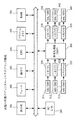
図1は、この発明の実施の形態に係るディジタル・ミキサの機能構成を示す。101〜105は、ミキシング処理への入力を示す。MADin101は、マイク信号のアナログ/ディジタル変換入力ボードによる入力を示す。このボードは1枚のボードで2チャンネル分の入力を行なうことができる。ADin102は、ライン信号のアナログ/ディジタル変換入力ボードによる入力を示す。このボードは、1枚のボードで4チャンネル分の入力を行なうことができる。Din103は、ディジタル入力ボードによる入力を示す。このボードは1枚で8チャンネル分のディジタル入力を行なうことができる(ただし、ラインを2つ使用する)。以上のMADin101、ADin102、およびDin103の3種類のボードは、ボード単位で80枚まで増設することができる。ボードは、インターフェースボックスに差し込むことによって増設でき、ここでは1個で8枚のボードを差せるボックスが10個まで接続できるようにしている。最大、4入力×80枚で、320入力となる。
【0012】
内蔵エフェクタ104は、本ディジタル・ミキサに内蔵してある8個のエフェクタからの入力を示す。それぞれ、ステレオ信号を入力し、選択されたエフェクトを付与してステレオ信号を出力するエフェクタである。内蔵イコライザ105は、本ディジタル・ミキサに内蔵してある24個のイコライザからの入力である。それぞれ、シングル信号を入力し、イコライザ処理してシングル信号を出力するものである。なお、「シングル」は、ステレオではない単一チャンネルであることを示すものとする。
【0013】
入力パッチ111は、上述した最大320シングル入力(MADin101、ADin102、Din103)、内蔵エフェクタ出力(8ステレオ出力)、および内蔵イコライザ出力(24シングル出力)から、入力チャンネル(48シングル入力)およびステレオ入力チャンネル(4ステレオ入力)への任意結線を行なう。その設定は、ユーザが所定の画面を見ながら任意に行なうことができる。
【0014】
入力チャンネル112には、入力パッチ111で選択された入力信号が入力する。同様にステレオ入力チャンネル113には、入力パッチ111で選択された入力信号が入力する。入力チャンネル112とステレオ入力チャンネル113は、共に後述する図2(a)に示す構成を備え、これらの違いは、ステレオ入力チャンネル113ではステレオの左信号(L)と右信号(R)がペアで制御される点である。入力チャンネル112からは、48本のMIXバス114あるいはステレオバス(Stereo_L/R)115の任意のチャンネルへ選択的に出力することができる。同様に、ステレオ入力チャンネル113からは、MIXバス114あるいはステレオバス115の任意のチャンネルへ選択的に出力できる。入力チャンネル112およびステレオ入力チャンネル113の各チャンネルでは、各MIXバス114およびステレオバス115への送出レベルをそれぞれ独立に設定することができる。また、入力チャンネル112およびステレオ入力チャンネル113から、後述するCUE_L/Rバス116あるいはKEY_INバス117へ選択的に出力をすることもできる。
【0015】
MIXバス114は、入力チャンネル112あるいはステレオ入力チャンネル113から入力する信号をミキシングする。ミキシングされた信号は、対応するMIX出力チャンネル122に出力される。MIXバス114とMIX出力チャンネル122とは、1対1の対応で各チャンネルが対応づけられている。ステレオバス115は、入力チャンネル112あるいはステレオ入力チャンネル113から入力する信号をミキシングする。ミキシングされたステレオ信号は、2つのステレオ出力チャンネル121へ並行して出力される。CUE_L/Rバス116は、各チャンネルにどのような信号が入力しているかを確認するためのバスである。後述するように各チャンネル操作子の下にCUEボタンが設けられており、それをオンすると、そのチャンネルの信号のみがこのバス116を経由して例えばヘッドフォンなどで確認できる。KEY_INバス117は、シングル入力が4チャンネル分のバスであり、コンプレッサを制御するためのものである。
【0016】
ステレオ出力チャンネル121は、ステレオのLとRが常時ペアで制御される。ステレオ出力チャンネル121の出力は、出力パッチ124およびマトリックス出力チャンネル123へ出力される。MIX出力チャンネル122は、MIXバス114からの出力を出力パッチ124またはマトリックス出力チャンネル123へ出力する。MIX出力チャンネル122では、(2N+1)番目のチャンネルと(2N+2)番目のチャンネルをペアにすることができる。
【0017】
マトリックス出力チャンネル123は、ステレオ出力チャンネル121とMIX出力チャンネル122から任意の数の信号を選択的に入力することができ、選択入力されたこれらの信号をさらにミキシングすることができる。信号処理の構成は、ステレオ出力チャンネル121およびMIX出力チャンネル122と同様である。マトリックス出力チャンネル123の出力は、出力パッチ124へ出力される。
【0018】
出力パッチ124は、上述した3種類の出力チャンネル(72シングル出力+2ステレオ出力)から、最大192シングル出力(DAout、Dout)、内蔵エフェクタ(8ステレオ入力)、あるいは内蔵イコライザ(24シングル入力)への任意の結線を行なう。DAout131は、ディジタル/アナログ変換出力ボードへの出力を示す。このボードは、1枚で4チャンネル分の出力を行なうことができる。Dout132は、ディジタル出力ボードへの出力を示す。このボードは、1枚で8チャンネル分の出力を行なうことができる(ラインを2つ使用)。出力パッチ124からの出力は、内蔵エフェクタ104あるいは内蔵イコライザ105に出力することもできる。
【0019】
なお、図面の簡単化のため、コンソール側の入力およびトークバックインなどの入力、コンソール側の出力およびキューアウトなどの出力、インサートエフェクトのための結線、並びに、モニタ出力のための結線などは省略している。
【0020】
図2(a)は、図1の入力チャンネル112の1つのチャンネルの構成を示す。入力チャンネル201は、デエンファシス211、ハイパスフィルタ(HPF)212、4バンドPEQ(プログラマブルイコライザ)213、ノイズゲート214、コンプレッサ215、遅延回路216、およびフェーダ217を備えている。デエンファシス211は、周波数特性を整えるフィルターである。ノイズゲート214は、信号レベルが下がったときノイズが残らないように閉じる(信号線の切断)ためのゲートである。コンプレッサ215は、自動ゲイン調整を行なうためのものである。遅延回路216は、コンサートホールなどでスピーカが複数置かれる場合に、それぞれの楽音が打ち消し合うことがないように、位相合わせを行なうためのものである。フェーダ217は、レベル調整のためのボリュームである。ステレオ入力チャンネル113の構成も図2(a)と同じである。ただし、ステレオ入力チャンネル113ではステレオの左信号(L)と右信号(R)がペアで制御されるようになっている。
【0021】
図2(b)は、図1のMIX出力チャンネル122の1つの出力チャンネルの構成を示す。出力チャンネル202は、6バンドPEQ221、コンプレッサ222、遅延回路223、およびフェーダ224を備える。ステレオ出力チャンネル121およびマトリックス出力チャンネル123の構成も、基本的には図2(b)と同じである。ただし、ステレオ出力チャンネル121ではステレオの左信号(L)と右信号(R)がペアで制御されるようになっている。また、マトリックス出力チャンネルについては、6バンドPEQの前段に、ステレオ出力チャンネルおよびMIX出力チャンネルのうちの当該マトリックス出力チャンネルの入力元として設定された1ないし複数を選択的にミキシングするミキシング部が備えられている。
【0022】
図3に、本実施の形態のディジタル・ミキサのブロック構成を示す。このディジタル・ミキサは、表示器301、フェーダ302、操作子303、中央処理装置(CPU)304、フラッシュメモリ305、ランダムアクセスメモリ(RAM)306、PC入出力インターフェース307、および信号処理部(DSP)308を備えている。表示器301、フェーダ302、および操作子303は、このディジタル・ミキサのパネル上に設けられており、ユーザが参照し、あるいは操作するためのものである。CPU304が実行する動作プログラムは、フラッシュメモリ305に記憶されている。また図9で後述するような各種のデータも、フラッシュメモリ305に記憶されている。CPU304は、操作子303およびフェーダ302の操作を検出し、DSP308の動作、表示器301の表示内容、フェーダ302の位置などを制御する。フェーダ302は、モータが付属するいわゆるムービングフェーダである。CPU304は、フェーダ302の位置を検出できるとともに、CPU304からの指示に応じてフェーダ302を指定された位置に移動することができる。
【0023】
DSP(ディジタル・シグナル・プロセッサ)308は、図1で説明したような機能構成のミキサ処理を行なうための信号処理部である。DSP308には、信号の入出力のために入力側にコネクタ1〜10(321〜323)、出力側にコネクタ1〜6(331〜333)が設けられている。1つの入力コネクタ321〜323には、図1で説明したインターフェースボックスとして、アナログ/ディジタル変換ボックスまたはディジタルインターフェースボックスのいずれかを接続することができる。1つのアナログ/ディジタル変換ボックスには、A/D変換ボード(図1のMADin101)を8枚まで増設することができる。各アナログ/ディジタル変換入力ごとに、ゲイン(ボリューム)と極性の設定が可能である。1つのディジタルインターフェースボックスには、ディジタルI/Oボード(図1のDin103、Dout132)を8枚まで増設することができる。
【0024】
また、DSP308の出力側の1つのコネクタ331〜333には、図1で説明したインターフェースボックスとして、ディジタル/アナログ変換ボックスまたはディジタルインターフェースボックスのいずれかを接続することができる。1つのディジタル/アナログ変換ボックスには、D/A変換ボード(図1のDAout131)を8枚まで増設することができる。各ディジタル/アナログ変換出力ごとにゲインと極性の設定が可能である。なお、ディジタルインターフェースボックスに差し込むディジタルI/Oボードは入出力両用でよいから、その場合は、DSP308の入力側と出力側のディジタルインターフェースボックスを共用することになる。
【0025】
図4に、この実施の形態のディジタル・ミキサの外部パネルの構成図を示す。パネル400上には、それぞれセクションに分けられて表示器や各種の操作子などが配置されている。401は入力チャンネルセクション、403は表示部のセクション、404はマトリックス(MATRIX)チャンネルセクション、405はMIXチャンネルセクション、408はコントロール/メモリセクションを、それぞれ示す。
【0026】
以下、各セクションについて詳細に説明する。
【0027】
図5に、入力チャンネルセクション401の詳細な構成を示す。入力チャンネルセクション401は、図1の入力チャンネル112の各チャンネルのゲイン設定などを行なう部分である。縦長の部分510で1チャンネルに対応する1セットの操作子群を示し、これを幾つか並べて入力チャンネルセクション401を構成している。1チャンネルの操作子群510は、選択された1系統のMIXバス114へのセンドレベルを設定するコントローラ(ロータリーエンコーダ)511、ステレオバス115に信号を送り込む際のパンを設定するコントローラ513、ステレオバス115へのアサインのオン/オフを設定するスイッチ515、ヘッドアンプゲイン調整を行なうコントローラ516、この入力チャンネルに割り当てられたショートネームを表示する表示部519、この入力チャンネルのオン/オフを設定するスイッチ520、ゲイン調整のためのモータ付きムービングフェーダ521、および、この入力チャンネルの信号をCUE_L/Rバス116に送り込む設定を行なうためのCUEスイッチ522を備える。コントローラ511,513,516の周囲には、それらのコントローラによる設定レベルを示すLEDのインジケータ512,514,517が設けてある。入力チャンネルセクション401のコントローラ511の上部には、コントローラ511で操作されるセンドレベルがどのMIXバスのセンドレベルかを選択するためのINCキー502とDECキー503、および、その選択されたMIXバスに割り当てられているショートネームを表示する表示部501が設けられている。
【0028】
図8に、コントローラとインジケータの詳細な外観を示す。801はユーザが操作するコントローラのつまみである。802はその周囲に配置されたLEDである。LED802は、このコントローラ801で設定されている値を示すインジケータになっている。
【0029】
図6(a)に、マトリックス(MATRIX)チャンネルセクション404の詳細な構成を示す。マトリックスチャンネルセクション404は、図1のマトリックス出力チャンネル123のレベル調整などを行なう部分である。610で、マトリックス出力チャンネル123の1チャンネルに対応する1セットの操作子群を示し、これを幾つか並べてマトリックスチャンネルセクション404を構成している。1チャンネルの操作子群610は、このチャンネルに割り当てられたショートネームを表示する表示部611、このチャンネルのオン/オフの設定を行なうためのスイッチ612、このチャンネルの出力レベルを設定するためのコントローラ613、設定された出力レベルを表すインジケータ614、この入力チャンネルの信号をCUE_L/Rバス116に送り込む設定を行なうためのCUEスイッチ615、および、各種の設定を行なうためのSELスイッチ616を備える。
【0030】
図6(b)に、MIXチャンネルセクション405の詳細な構成を示す。MIXチャンネルセクション405は、図1のMIX出力チャンネル122のレベル調整などを行なう部分である。630で、MIX出力チャンネル122の1チャンネルに対応する1セットの操作子群を示し、これを幾つか並べてMIXチャンネルセクション405を構成している。1チャンネルの操作子群630の構成は、図6(a)のマトリックスチャンネルセクションの操作子群610の構成と同様である。631〜636の各部は、611〜616の各部に対応している。
【0031】
図7は、コントロール/メモリセクション408の詳細な構成を示す。コントロール/メモリセクション408は、ダイレクトリコールスイッチ711、プレビュースイッチ712、履歴「戻る」スイッチ713、リコールスイッチ714、ストアスイッチ715、LED716、テンキー717、INCキー718、DECキー719、カーソル移動キー720、トラックパッド721、左パッドスイッチ722、右パッドスイッチ723、およびデリートキー724を備えている。
【0032】
ダイレクトリコールキー711は、各スイッチにシーン番号を割り当てワンタッチでそのシーンを呼び出すためのスイッチである。ダイレクトリコールキー711は、12個あり、12シーンを直接呼び出すことができる。
【0033】
プレビュースイッチ712は、オンするごとに、プレビューモードと非プレビューモードとを交互に切り替えるためのスイッチである。非プレビューモードは、現在のミキシング状態を直接操作できるモードである。非プレビューモードにおいて、例えば何れかのコントローラやフェーダを操作すると、現在のシーンの状態がその操作に応じて変更される。プレビューモードは、現在のシーンのミキシング状態はそのままとして、他のシーンの設定を呼び出して確認や変更(プレビュー)することができるモードである。プレビュースイッチ712をオンしたときの処理は、図11で詳しく説明する。
【0034】
履歴「戻る」スイッチ713は、シーンごとに記憶しているそのシーンの過去の設定を呼び出すためのスイッチである。履歴「戻る」スイッチ713をオンしたときの処理は、図16で詳しく説明する。
【0035】
リコールスイッチ714は、任意のシーンを呼び出すことを指示するスイッチである。シーンの呼び出しは、以下のような操作で行なう。プレビューモードの場合はプレビューしているシーンのシーン番号が、非プレビューモードの場合は現在設定されているシーンのシーン番号が、LED716に表示されている。この状態で、LED716の表示では小数点が固定表示してあり、LED716の整数部の表示がシーン番号を表す。小数部は、整数部のシーン番号のシーンの過去の履歴(後に詳述する)を表す。ここでテンキー717を操作して任意のシーン番号(整数部)を入力しリコールスイッチ714をオンすることにより、当該シーン番号の(最新の)シーンを呼び出すことができる。なお、テンキー717は小数点キーも備えており、整数部に続いて小数点キーをオンした後、小数点以下の数値を入力し、その後リコールスイッチ714をオンすることにより、任意のシーンの過去のデータを直接呼び出すこともできる。
【0036】
プレビューモードまたは非プレビューモードの何れの場合でも、INCキー718またはDECキー719によりシーンを呼び出すことができる。LED716に現在のシーンのシーン番号が表示されているときINCキー718をオンすると、整数部がそのシーン番号より大きい次のシーン番号の(最新の)シーンが呼び出される。この場合、デリートキー724により削除されたシーンについては後述するようにブランクが設定されるので、INCキー718がオンされたときは、ブランクのシーンはスキップし、ブランクでないシーンのうちの次のシーンを呼び出すものとする。DECキー719は、シーン番号が小さくなる方向に進むことを除いて、INCキー718と同様である。
【0037】
INCキー718やDECキー719、あるいはテンキー717とリコールキー714の操作によるシーン番号の変更時の一般的な処理手順は、図10で説明する。特に、INCキー718やDECキー719が操作されたときのシーン番号の変更時に、ブランクのシーンデータをスキップしてシーン番号が増減される処理については、図12で説明する。
【0038】
プレビューモードまたは非プレビューモードで上述したように任意のシーンを呼び出した後、図4〜図6で説明したような各種の操作子を操作して、そのシーンの各種の設定を変更することができる。プレビューモードでの設定の変更は、現在有効になっているシーンのミキシング状態などには影響しない。非プレビューモードでの設定の変更は、現在のミキシング状態などに直接反映する。プレビューモードまたは非プレビューモードの何れの場合も、設定の変更は一時的な変更である。設定変更の後、ストアスイッチ715のオンにより、指定したシーン番号に設定変更後のシーンのデータをストアすることができる。ストアスイッチ715をオンすると、どのシーン番号にストアするかの問合せのメッセージが表示され、それに応じてテンキー717によりストアするシーン番号(整数部のみ)を入力し、再度ストアスイッチ715をオンすることにより、現在のシーンの状態をそのシーン番号の領域にストアすることができる。ストアスイッチ715をオンしたときの処理については、図14で説明する。
【0039】
デリートキー724をオンすることにより、現シーン番号のシーンを削除することができる。ただし、削除されてもシーンのデータは過去の履歴を示すデータとして保持されている。そのシーンが削除されたことを示すブランクフラグがセットされるだけである。デリートキー724をオンしたときの処理については、図15で説明する。
【0040】
カーソル移動キー720、トラックパッド721、左パッドスイッチ722、および右パッドスイッチ723は、表示部のセクション403(図3の301)に表示された画面を参照してユーザが各種の設定変更を行なう際に使用する。
【0041】
図9は、図3のフラッシュメモリに確保されたデータ記憶領域のメモリマップを示す。データ記憶領域には、100個のパッチデータを格納するための配列PD(1)〜PD(100)、100個のネームデータを格納するための配列ND(1)〜ND(100)、100個のユニットデータを格納するための配列UD(1)〜UD(100)、1000個のシーンエントリデータを格納するための配列SED(1)〜SED(1000)、および10000個のシーンデータを格納するための配列SD(1)〜SD(1000)が設けられている。
【0042】
配列PD(1)〜PD(100)に記憶するパッチデータとは、図1で説明した入力パッチ111および出力パッチ124の結線状態を表すデータである。配列ND(1)〜ND(100)に記憶するネームデータとは、図1で説明した入力チャンネル112、MIX出力チャンネル122、およびMATRIX出力チャンネルの各チャンネルとそこに割り当てた名前(ショートネームなど)との対応関係を示すデータである。配列UD(1)〜UD(100)に記憶するユニットデータとは、入力側インターフェースボックスに接続された各入力ボードの各入力ごとの設定データ(ゲインや極性など)、および、出力側インターフェースボックスに接続された各出力ごとの設定データ(ゲインや極性など)を示す。
【0043】
配列SED(1)〜SED(1000)に記憶するシーンエントリデータとは、登録された1つのシーンを特定する情報である。なお、この配列の添え字の番号がシーン番号(整数部)に対応する。例えば、SED(2)は、シーン番号が「2」のシーンに対応する。
【0044】
図9に示すように、1つのシーンエントリデータは、シーン名SNAME、そのシーン名の最新のシーンデータSDを指すポインタSDN、ブランクフラグBF、および履歴数HNからなる。シーン名SNAMEは、登録されたシーンの名称である。ポインタSDNで指すシーンデータSDが、当該シーンのシーンデータのうちの最新のデータである。ブランクフラグBFは、その値が「0」のとき、ポインタSDNで指すシーンデータSDのシーンデータ本体が有効であることを示す。ブランクフラグBFの値が「1」のときは、ポインタSDNで指すシーンデータSDのシーンデータ本体が無効である(削除されている)ことを示す。この実施の形態では、シーンを任意のシーン番号にストアしたときには、ストアしたデータが最新のシーンとして記憶されるとともに、そのシーン番号のシーンデータが既に存在していたときには、それを過去のシーンデータとして保持しておく。履歴数HNは、過去のシーンデータも含めて、現在幾つのシーンデータが保持されているか、その数を示すデータである。1つのシーン番号(整数部)で最大10個までのシーンデータを保持することができるようになっている。
【0045】
図9に示すように、1つのシーンデータは、履歴の次のシーンデータSDへのポインタNSDN、前のシーンデータSDへのポインタPSDN、シーンデータの本体、パッチデータへのリンクPDL、ネームデータへのリンクNDL、およびユニットデータへのリンクUDLからなる。
【0046】
次のシーンデータSDへのポインタNSDNは、当該シーンデータの1つ前(過去)のシーンデータを指すポインタである。前のシーンデータSDへのポインタPSDNは、当該シーンデータの1つ後(より現在に近い方)のシーンデータを指すポインタである。これらのポインタNSDNとPSDNにより、同じシーン番号の過去から現在のシーンデータはチェインされる。あるシーン番号における最新のシーンデータについては、それより新しいシーンデータは存在しないということだから、ポインタPSDNにはそのことを示す識別子(例えば、16進のFFなど)が設定される。あるシーン番号における最も過去のシーンデータについては、それより過去のシーンデータは存在しないということだから、ポインタNSDNにはそのことを示す識別子(例えば、16進のFFなど)が設定される。履歴数HNの最大値は10個であるので、ポインタNSDNとPSDNによりチェインされているシーンデータが10個のときに、そのシーン番号に新たなシーンデータがストアされたときには、最も過去のシーンデータが破棄される。
【0047】
なお、シーン番号の小数部で、そのシーンデータがいつの履歴であるかを表す。例えば、シーン番号の整数部が99のシーンでは、最新のシーンデータはシーン番号が99.0(ポインタSDNが指す第1のシーンデータSD)、1つ前の過去のシーンデータはシーン番号が99.1(第1のシーンデータSDのポインタNSDNが指す第2のシーンデータSD)、さらにその前の過去のシーンデータはシーン番号が99.2(第2のシーンデータSDのポインタNSDNが指す第3のシーンデータSD)、というように特定される。
【0048】
シーンデータの本体には、各入力チャンネルの設定(各チャンネルのエフェクト、フェーダ、出力先、出力レベルなど)、各出力チャンネルの設定(各チャンネルのエフェクト、フェーダ、マトリックス出力チャンネルの入力元、入力レベルなど)、内蔵エフェクタの設定、内蔵イコライザの設定、およびモニタの設定などのデータが格納される。パッチデータへのリンクPDL、ネームデータへのリンクNDL、およびユニットデータへのリンクUDLには、当該シーンで使用するパッチデータPD、ネームデータND、およびユニットデータUDをそれぞれ指すポインタが設定される。
【0049】
なお、パッチデータPD、ネームデータND、およびユニットデータUDは、従来のミキサではシーンデータの中に含まれていたので記憶容量およびレスポンスの点で効率が悪かった。しかし、これらのデータはシーンごとに変更されるとは限らず、一連の複数のシーンではこれらの設定を変更しない場合も少なくない。その一方で、上述のシーンデータ本体に含まれる設定データは、シーンごとに変更される可能性が高いデータである。そこで、この実施の形態では、シーンデータ中にリンクPDL、NDL、およびUDLを設けて、シーンが変更されてもこれらのデータが同じであれば同じデータへのリンクを持つことで対処した。これにより、シーンデータごとにこれらのデータを持つ必要がなくなるので、記憶容量を抑えることができる。また、シーンが変更になっても、リンクPDL、NDL、またはUDLが指すデータが変わらなければ、その設定状態は変更する必要がなくなるので、レスポンスも速い。また、当該ディジタル・ミキサは、シーンのネームや設定値等をキーとしてシーンの並べ替えを行なう機能を有しているが、各リンクを個々のシーンデータ毎に記憶しているため、そういった並べ替えを行なった場合でも各シーン毎の設定内容が崩れてしまうことがない。
【0050】
なお、処理手順は後述するが、あるシーンの削除が指示されたとき(シーンデリート操作)には、そのシーンのシーンエントリデータSEDのブランクフラグBFを「1」にするだけとする。これにより、削除されたシーンについても、シーンエントリデータSEDのポインタSDNからチェインをたどって過去のシーンデータにアクセスできるようになっている。
【0051】
パッチデータPD、ネームデータND、およびユニットデータUDの設定変更は、所定の操作により表示器セクション403にこれらのデータの設定変更画面を表示し、図7で説明したテンキー717、カーソル移動キー720、トラックパッド721、左パッドスイッチ722、および右パッドスイッチ723などを操作することにより行なうことができる。
【0052】
図10は、図7で説明したテンキー717およびリコールキー714、あるいはINCキー718またはDECキー719の操作により、シーン番号が変更されたときの処理手順を示す。ステップ1001で、現在のモードがプレビューモードか非プレビューモードかを判定する。フラグPNは、プレビューモードのとき「1」、非プレビューモードのとき「0」となるフラグである。非プレビューモードであるときは、ステップ1002で、操作内容に応じてシーン番号SNを変更し、変更後のシーン番号SNに応じたシーンのデータを図9のデータ記憶領域から主ワークメモリにロードするとともに、対応する制御データをDSP308に送出して、DSP308の設定を変更し、処理を終了する。ステップ1001でプレビューモードであるときは、ステップ1003で、操作内容に応じてプレビューシーン番号PSNを変更し、変更後のプレビューシーン番号PSNに応じたシーンのデータを図9のデータ記憶領域からプレビュー用ワークメモリにロードする。この場合、DSP308に対して、対応する制御データを送出することはしない。
【0053】
図11に、図7のプレビュースイッチ712をオンしたときの処理手順を示す。ステップ1101で、プレビューモードか非プレビューモードかを示すフラグPNを反転させる。次にステップ1102で、プレビューモードか非プレビューモードかを判定する。非プレビューモードのときは、ステップ1103で、主ワークメモリをパネル制御に使用するように設定して、処理を終了する。これ以後は、主ワークメモリ上に展開されているシーンのデータ(このデータがDSPにおけるミキサ処理に反映される)に対して、パネル上の各種操作子の操作により変更が行なえる。ステップ1102でプレビューモードであるときは、ステップ1104で、主ワークメモリの内容をプレビュー用ワークメモリにコピーし、プレビューシーン番号PSNに現在のシーン番号SNをコピーする。またステップ1105で、プレビュー用ワークメモリをパネル制御に使用するよう設定し、処理を終了する。これ以後は、プレビュー用ワークメモリのシーンのデータに対して、パネル上の各種操作子によって設定変更が可能になる。主ワークメモリのデータに応じて、パネル上の表示器の表示内容や操作子の位置、および、DSPのミキサ処理が制御される。一方、プレビュー用ワークメモリのデータに応じて、パネル上の表示器の表示内容や操作子の位置が制御されるが、DSPのミキサ処理は制御されない。
【0054】
図12は、非プレビューモードにおいて図7のINCキー718をオンしたときの処理手順を示す。シーン番号が変更されたときの処理は図10で説明したが、図12は、特にブランクのシーンをスキップしてシーンを変更する処理、およびリンクを辿ってデータを呼び出す処理に着目した流れ図である。
【0055】
まずステップ1201で、現在のシーン番号SNがシーン番号の最大値MAX以上になっているか否か判別する。MAXに到達していたときは、ステップ1211でその旨を表示器に表示し、処理を終了する。ステップ1201でシーン番号が最大値MAXより小さいときは、ステップ1202で、シーン番号SNの整数部に1を加えた値を新たなシーン番号SNとし、ステップ1203でそのシーンがブランクであるか否か判定する。ブランクであるか否かは、そのシーンのシーンエントリデータSED(図9)のブランクフラグBFを参照することにより分かる。シーン番号SNのシーンがブランクであるときは、ステップ1201に戻る。
【0056】
ブランクでないときは、ステップ1204で、そのシーン番号SN(整数部)の最新のシーンデータのパッチリンクPDLを参照し、現在の設定状態(図12の処理を開始したときのシーン番号SNのシーンデータのパッチリンクPDL)から変更となっているか否か(両パッチリンクPDLが同じか否か)を判別する。変更になっているときは、ステップ1205でそのパッチデータPDを呼び出す。次にステップ1206で、そのシーン番号SNのシーンのネームリンクNDLを参照し、現在の設定状態(同シーンデータのネームリンクNDL)から変更になっているか否かを判別する。変更になっているときは、ステップ1207でそのネームリンクのネームデータNDを呼び出す。次にステップ1208で、そのシーン番号SNのシーンのユニットリンクUDLを参照し、現在の設定状態(同シーンデータのユニットリンクUDL)から変更になっているか否かを判定する。変更になっているときは、ステップ1209でそのユニットリンクのユニットデータを呼び出す。最後にステップ1210で、そのシーン番号SN(整数部)が示す最新のシーンデータをフラッシュメモリ305上の図9のデータ記憶領域から主ワークメモリへロードするとともに、対応する制御データをDSP308に送出して、処理を終了する。
【0057】
図12では非プレビューモードにおけるINCキー718のオンの処理を説明したが、DECキー719のオンの場合およびプレビューモードの場合も同様の手順である。ただし、DECキー719のオンではシーン番号を減少させる方向に変更するものとする。また、プレビューモードの場合は、呼び出したデータは主ワークメモリではなくプレビュー用ワークメモリに展開するものとし、また呼び出したデータをDSP308に送出することはしない。
【0058】
図13は、フェーダの操作が行なわれたときの処理手順を示す。図13(a)は非プレビューモードのとき、図13(b)はプレビューモードの場合である。非プレビューモードでフェーダが操作されたとき、ステップ1301で、そのフェーダの検出値により、主ワークメモリ中の当該フェーダに対応するデータを更新する。次にステップ1302で、当該フェーダに対応する制御データをDSP308に送出し、処理を終了する。プレビューモードのときは、ステップ1311で、そのフェーダの検出値により、プレビュー用ワークメモリ中の当該フェーダのデータを更新し、処理を終了する。この場合、当該フェーダの操作に応じてDSP308のミキサ処理は制御されない。
【0059】
図14は、図7のストアスイッチ715がオンされたときの処理手順を示す。この処理が開始されるときは、ストアすべきシーン番号が指定されているものとする。ステップ1401で、フラッシュメモリの図9のデータ記憶領域中にシーンデータSDの記憶領域を1つ割り当てる。ステップ1402で、割り当てた領域SDに主ワークメモリ(非プレビューモードのとき)またはプレビュー用ワークメモリ(プレビューモードのとき)のデータをコピーする。ステップ1403で、前記割り当てた領域SDが先頭(最新のシーンデータ)となるように当該シーン番号の履歴のリンクを更新する(該領域SDを該履歴のリンクの先頭に接続する)とともに、更新後の履歴のリンク数が10以下になるように調整する(10を越えるときは、当該リンクの末尾の一番古いシーンデータを当該リンクから切り離す)。ステップ1404で、当該シーン番号のエントリのポインタが前記割り当てた領域SDを指すように更新するとともに、更新された履歴のリンク数で履歴数HNを更新し、さらに、フラグBFを「0」に設定して処理を終了する。
【0060】
図15は、図7のデリートキー724がオンされたときの処理手順を示す。ステップ1501で、当該シーン番号のエントリのブランクフラグBFを「1」に設定し、処理を終了する。
【0061】
図16は、図7の履歴「戻る」スイッチ713をオンしたときの処理手順を示す。ステップ1601で、現在のシーン番号SNからポインタを辿って履歴の最後(最も過去のデータ)になっているか否か判別する。現在のシーンが最も過去のデータであるときは、それ以上履歴を戻ることができないから、処理を終了する。履歴の最後でないときは、ステップ1602でシーン番号SNに0.1を加算し、ステップ1603で新しいシーン番号SNに基づくリコール処理を行ない、処理を終了する。なお、ここでは不図示だが、履歴「進む」スイッチにより、過去のデータから最新のデータに向かってリコールすることもできる。
【0062】
この実施形態のシステムでは、各操作子やスイッチなどが何の信号の制御にアサイン(割り当て)されているかをユーザが容易に把握できるようにするため、図5の519、図6(a)の611、および図6(b)の631に示すように、ショートネームを表示する。各チャンネルへのショートネームの割り当ては、ユーザが所定の画面を参照しながら任意に行なえるようになっている。
【0063】
【発明の効果】
以上説明したように、この発明によれば、シーンのデータがブランクを含むものとし、INCスイッチやDECスイッチが操作されてシーン番号が増減されたとき、そのシーン番号がブランクであったときにはその次のシーン番号に自動的に増減させるようにしているので、ブランク(シーンデータが無い)のシーンはスキップしてINCスイッチやDECスイッチによるシーン番号の増減ができる。したがって、INCスイッチやDECスイッチの空打ちを行なわなくて済み操作が煩雑でなくなる。
【図面の簡単な説明】
【図1】この発明の実施の形態に係るディジタル・ミキサの機能構成図
【図2】実施形態におけるチャンネルの構成を示す図
【図3】実施の形態のディジタル・ミキサのブロック構成図
【図4】実施の形態のディジタル・ミキサの外部パネルの構成図
【図5】入力チャンネルセクションの詳細な構成図
【図6】マトリックスチャンネルセクションとMIXチャンネルセクションの詳細な構成図
【図7】コントロール/メモリセクションの詳細な構成図
【図8】コントローラとインジケータの詳細な外観図
【図9】データ記憶領域のメモリマップを示す図
【図10】シーン番号が変更されたときの処理手順を示すフローチャート図
【図11】プレビュースイッチをオンしたときの処理手順を示すフローチャート図
【図12】非プレビューモードにおいてINCキーをオンしたときの処理手順を示すフローチャート図
【図13】フェーダの操作が行なわれたときの処理手順を示すフローチャート図
【図14】ストアスイッチがオンされたときの処理手順を示すフローチャート図
【図15】デリートキーがオンされたときの処理手順を示すフローチャート図
【図16】履歴「戻る」スイッチをオンしたときの処理手順を示すフローチャート図
【符号の説明】
101…MADin(マイク信号のアナログ/ディジタル変換入力ボード)、102…ADin(ライン信号のアナログ/ディジタル変換入力ボード)、103…Din103(ディジタル入力ボード)、104…内蔵エフェクタ、105…内蔵イコライザ、111…入力パッチ、112…入力チャンネル、113…ステレオ入力チャンネル、114…MIXバス、115…ステレオバス、116…CUE_L/Rバス、117…KEY_INバス、121…ステレオ出力チャンネル、122…MIX出力チャンネル、123…マトリックス出力チャンネル、124…出力パッチ、131…DAout(ディジタル/アナログ変換出力ボード)、132…Dout(ディジタル出力ボード)。[0001]
BACKGROUND OF THE INVENTION
The present invention relates to a digital mixer that performs intensive control of audio equipment in a venue for performing concerts and plays.
[0002]
[Prior art]
2. Description of the Related Art Conventionally, a mixer device for controlling audio equipment in a venue such as a concert or a theater is known. In such venue audio equipment, a large number of microphones and a large number of speakers are used, and sound effects are used in a wide variety. The mixer device centrally controls how many inputs are mixed, how effects are applied, and which output system is output. For this reason, some conventional mixer apparatuses can store a mixing state and a connection state for each scene as a scene (SCENE). By storing the set state as one scene and recalling the recalled scene later, the set state can be easily reproduced.
[0003]
As a method for calling a scene, for example, a method is used in which the scene number is incremented / decremented one by one with an INC / DEC switch, and the scene data of the incremented / decremented scene number is called. A method is also known in which a specific scene number is input using a numeric keypad, and a scene with that number is directly called.
[0004]
[Problems to be solved by the invention]
By the way, scene data is not stored for all consecutive scene numbers. However, in the conventional mixer apparatus, the scene number is increased or decreased one by one by the INC / DEC switch, so that all the scene numbers having no scene data must be turned. Therefore, the operation has become very complicated.
[0005]
In addition, many scenes are stored in the scene memory, but in a series of multiple scenes of events such as concerts and plays where a mixer is used, it is desired to easily call a specific scene that is an event delimiter There is a request. However, as described above, in order to move to a desired scene on the way, the “INC / DEC” switch must be operated many times, or the scene number of the scene must be directly input with the numeric keypad. there were.
[0006]
In view of the above-described problems in the prior art, the present invention eliminates the troublesome operation of turning over all scene numbers without scene data when calling a scene with the INC / DEC switch, and is a specific event delimiter. An object of the present invention is to provide a digital mixer that can meet a demand for easily recalling a scene.
[0007]
[Means for Solving the Problems]
In order to achieve this object, the invention according to
[0010]
DETAILED DESCRIPTION OF THE INVENTION
Embodiments of the present invention will be described below with reference to the drawings.
[0011]
FIG. 1 shows a functional configuration of a digital mixer according to an embodiment of the present invention.
[0012]
The built-in
[0013]
The
[0014]
The input signal selected by the
[0015]
The
[0016]
In the
[0017]
The
[0018]
The
[0019]
For simplification of drawings, input on the console side and talkback-in, etc., output on the console side and output such as cue-out, connection for insert effects, and connection for monitor output are omitted. doing.
[0020]
FIG. 2A shows the configuration of one of the
[0021]
FIG. 2B shows a configuration of one output channel of the
[0022]
FIG. 3 shows a block configuration of the digital mixer of the present embodiment. The digital mixer includes a
[0023]
The DSP (digital signal processor) 308 is a signal processing unit for performing mixer processing having the functional configuration as described in FIG. The
[0024]
In addition, either the digital / analog conversion box or the digital interface box can be connected to the one
[0025]
FIG. 4 shows a configuration diagram of the external panel of the digital mixer of this embodiment. On the
[0026]
Hereinafter, each section will be described in detail.
[0027]
FIG. 5 shows a detailed configuration of the
[0028]
FIG. 8 shows the detailed appearance of the controller and the indicator.
[0029]
FIG. 6A shows a detailed configuration of the matrix (MATRIX)
[0030]
FIG. 6B shows a detailed configuration of the
[0031]
FIG. 7 shows a detailed configuration of the control /
[0032]
The
[0033]
The
[0034]
The history “return”
[0035]
The
[0036]
In either the preview mode or the non-preview mode, the scene can be called by the INC key 718 or the
[0037]
A general processing procedure when changing the scene number by operating the
[0038]
After calling an arbitrary scene as described above in the preview mode or the non-preview mode, various settings as described in FIGS. 4 to 6 can be operated to change various settings of the scene. . Changing the setting in the preview mode does not affect the mixing state of the currently active scene. Changes in settings in non-preview mode are directly reflected in the current mixing state. In either the preview mode or the non-preview mode, the setting change is a temporary change. After the setting change, the
[0039]
By turning on the
[0040]
The
[0041]
FIG. 9 shows a memory map of the data storage area secured in the flash memory of FIG. In the data storage area, arrays PD (1) to PD (100) for storing 100 patch data, arrays ND (1) to ND (100), 100 for storing 100 name data Arrays UD (1) to UD (100) for storing unit data, arrays SED (1) to SED (1000) for storing 1000 scene entry data, and 10,000 scene data are stored. Arrays SD (1) to SD (1000) are provided for this purpose.
[0042]
The patch data stored in the arrays PD (1) to PD (100) is data representing the connection state of the
[0043]
The scene entry data stored in the arrays SED (1) to SED (1000) is information for specifying one registered scene. The number of the subscript in this array corresponds to the scene number (integer part). For example, SED (2) corresponds to the scene with the scene number “2”.
[0044]
As shown in FIG. 9, one scene entry data includes a scene name SNAME, a pointer SDN indicating the latest scene data SD of the scene name, a blank flag BF, and a history number HN. The scene name SNAME is the name of the registered scene. The scene data SD pointed to by the pointer SDN is the latest data among the scene data of the scene. The blank flag BF indicates that the scene data body of the scene data SD pointed to by the pointer SDN is valid when the value is “0”. When the value of the blank flag BF is “1”, it indicates that the scene data body of the scene data SD pointed to by the pointer SDN is invalid (deleted). In this embodiment, when a scene is stored in an arbitrary scene number, the stored data is stored as the latest scene, and when the scene data of the scene number already exists, it is stored in the past scene data. Keep as. The history number HN is data indicating the number of scene data currently stored including past scene data. A single scene number (integer part) can hold up to 10 scene data.
[0045]
As shown in FIG. 9, one scene data includes a pointer NSDN to the next scene data SD in the history, a pointer PSDN to the previous scene data SD, the body of the scene data, a link PDL to the patch data, and name data. Link NDL and a link UDL to unit data.
[0046]
The pointer NSDN to the next scene data SD is a pointer that points to the previous scene data of the scene data. The pointer PSDN to the previous scene data SD is a pointer that points to the scene data that is one after the scene data (closer to the present). With these pointers NSDN and PSDN, the current scene data from the past of the same scene number is chained. Since there is no newer scene data for the latest scene data in a certain scene number, an identifier (for example, hexadecimal FF) indicating that fact is set in the pointer PSDN. Since there is no past scene data for the past scene data in a certain scene number, an identifier (for example, hexadecimal FF) indicating that fact is set in the pointer NSDN. Since the maximum value of the history number HN is 10, when the scene data chained by the pointers NSDN and PSDN is 10, and when new scene data is stored in the scene number, the oldest scene data Is destroyed.
[0047]
The decimal part of the scene number indicates when the scene data is a history. For example, in a scene whose scene number is 99, the latest scene data has a scene number of 99.0 (first scene data SD indicated by the pointer SDN), and the previous past scene data has a scene number of 99. .1 (the second scene data SD pointed to by the pointer NSDN of the first scene data SD), and the previous scene data before that has a scene number of 99.2 (the first scene data SD pointed to by the pointer NSDN). 3 scene data SD).
[0048]
The scene data itself contains settings for each input channel (effects, faders, output destination, output level, etc. for each channel), and settings for each output channel (input sources, input levels for each channel effect, fader, matrix output channel) Etc.), data such as built-in effector settings, built-in equalizer settings, and monitor settings are stored. In the link PDL to the patch data, the link NDL to the name data, and the link UDL to the unit data, pointers that respectively point to the patch data PD, name data ND, and unit data UD used in the scene are set.
[0049]
Note that the patch data PD, name data ND, and unit data UD were included in the scene data in the conventional mixer, so that the efficiency was poor in terms of storage capacity and response. However, these data are not always changed for each scene, and in many cases, these settings are not changed in a series of a plurality of scenes. On the other hand, the setting data included in the above-described scene data main body is data that is highly likely to be changed for each scene. Therefore, in this embodiment, the link PDL, NDL, and UDL are provided in the scene data, and if the data is the same even if the scene is changed, the link is made to the same data. Thereby, since it is not necessary to have these data for each scene data, the storage capacity can be suppressed. Even if the scene changes, if the data pointed to by the link PDL, NDL, or UDL does not change, the setting state does not need to be changed, and the response is fast. The digital mixer has a function for rearranging scenes using scene names and setting values as keys, but since each link is stored for each individual scene data, such rearrangement is performed. Even when the operation is performed, the setting contents for each scene are not destroyed.
[0050]
Although the processing procedure will be described later, when deletion of a certain scene is instructed (scene delete operation), the blank flag BF of the scene entry data SED of that scene is simply set to “1”. As a result, the deleted scene can be accessed by following the chain from the pointer SDN of the scene entry data SED.
[0051]
To change the setting of the patch data PD, name data ND, and unit data UD, a setting change screen for these data is displayed on the
[0052]
FIG. 10 shows a processing procedure when the scene number is changed by operating the
[0053]
FIG. 11 shows a processing procedure when the
[0054]
FIG. 12 shows a processing procedure when the
[0055]
First, in
[0056]
If not blank, in
[0057]
In FIG. 12, the process of turning on the INC key 718 in the non-preview mode has been described. However, when the
[0058]
FIG. 13 shows a processing procedure when the fader is operated. FIG. 13A shows the case of the non-preview mode, and FIG. 13B shows the case of the preview mode. When the fader is operated in the non-preview mode, in
[0059]
FIG. 14 shows a processing procedure when the
[0060]
FIG. 15 shows a processing procedure when the
[0061]
FIG. 16 shows a processing procedure when the history “return”
[0062]
In the system of this embodiment, in order to make it easy for the user to know what signal control each switch, switch, etc. is assigned (assigned) to, 519 in FIG. 5 and FIG. As shown at 611 and 631 in FIG. 6B, the short name is displayed. The user can arbitrarily assign a short name to each channel while referring to a predetermined screen.
[0063]
【The invention's effect】
As described above, according to the present invention, the scene data includes a blank, and when the INC switch or DEC switch is operated to increase or decrease the scene number, when the scene number is blank, the next Since the scene number is automatically incremented or decremented, a blank (no scene data) scene can be skipped and the scene number can be incremented or decremented by the INC switch or DEC switch. Accordingly, it is not necessary to perform the blanking of the INC switch or the DEC switch, and the operation is not complicated .
[Brief description of the drawings]
FIG. 1 is a functional configuration diagram of a digital mixer according to an embodiment of the present invention. FIG. 2 is a diagram showing a channel configuration in the embodiment. FIG. 3 is a block configuration diagram of a digital mixer in the embodiment. [Fig. 5] Detailed configuration diagram of input channel section [Fig. 6] Detailed configuration diagram of matrix channel section and MIX channel section [Fig. 7] Control / memory section FIG. 8 is a detailed external view of a controller and an indicator. FIG. 9 is a diagram showing a memory map of a data storage area. FIG. 10 is a flowchart showing a processing procedure when a scene number is changed. 11 is a flowchart showing a processing procedure when the preview switch is turned on. FIG. 12 is a non-preview mode. FIG. 13 is a flowchart showing the processing procedure when the INC key is turned on. FIG. 13 is a flowchart showing the processing procedure when the fader is operated. FIG. 14 shows the processing procedure when the store switch is turned on. FIG. 15 is a flowchart showing a processing procedure when the delete key is turned on. FIG. 16 is a flowchart showing a processing procedure when the history “return” switch is turned on.
DESCRIPTION OF
Claims (1)
前記ミキシング処理の設定状態を再現するためのデータを、複数のシーン毎に、シーン番号により特定される最新のデータとシーン番号および履歴番号により特定される複数の履歴データとを含めて、記憶するとともに、各シーン毎に当該シーンが削除されたか否かを示すブランクフラグを記憶した記憶手段と、
シーン番号を増減するINCスイッチおよびDECスイッチと、
シーン番号と履歴番号とを数値入力するためのテンキーと、
前記INCスイッチ若しくはDECスイッチの操作、または前記テンキーの操作で特定されるシーン番号乃至履歴番号に対応する前記シーンを指定する手段であって、前記INCスイッチおよびDECスイッチの操作に応じてシーン番号が増減されたとき、該シーン番号に対応するシーンの前記ブランクフラグがオンされていた場合はそのシーン番号の次のシーン番号に自動的に増減して前記シーンを指定するシーン指定手段と、
現在のミキシング処理の設定状態の保存を指示するストア指示手段と、
前記ストア指示手段による指示に応じて、現在のミキシング処理の設定状態を前記シーン指定手段により指定されたシーンの最新のデータとして前記記憶手段に書き込むとともに、当該シーンに対応する前記ブランクフラグをオフし、該指定されたシーンの最新のデータとして既に記憶されていたデータを該シーンの履歴データとして前記記憶手段に保持させる設定状態書込手段と、
指定されたシーンの削除を指示する削除指示手段と、
前記削除指示手段による指示に応じて、前記シーン指定手段により指定されているシーンに対応する前記ブランクフラグをオンする設定状態消去手段と、
前記記憶手段からシーンのデータの呼び出しを指示するリコール指示手段と、
前記リコール指示手段による指示に応じて、前記シーン指定手段において前記シーン番号乃至履歴番号により指定されているシーンのデータを前記記憶手段から呼び出し、前記ミキシング処理の設定状態を再現する設定状態再現手段と
を備えたことを特徴とするディジタル・ミキサ。A digital mixer that includes a display means and an operator on the panel, and optionally performs a mixing process on a plurality of acoustic signals input from a plurality of input systems, and outputs the mixed signals to a plurality of output systems.
Data for reproducing the setting state of the mixing process is stored for each of a plurality of scenes including the latest data specified by the scene number and a plurality of history data specified by the scene number and the history number. And storage means for storing a blank flag indicating whether or not the scene is deleted for each scene ;
And INC switch and DEC switch to increase or decrease the your scene number,
Numeric keypad for entering the scene number and history number numerically,
A means for designating the scene corresponding to a scene number or history number specified by the operation of the INC switch or DEC switch or the operation of the numeric keypad, and the scene number is determined according to the operation of the INC switch and the DEC switch. A scene designating unit for designating the scene by automatically increasing or decreasing to the next scene number of the scene number when the blank flag of the scene corresponding to the scene number is turned on ,
Store instruction means for instructing to save the current setting state of the mixing process;
In response to an instruction from the store instruction means, the current mixing process setting state is written in the storage means as the latest data of the scene designated by the scene designation means, and the blank flag corresponding to the scene is turned off. Setting state writing means for holding the data already stored as the latest data of the designated scene in the storage means as history data of the scene;
A deletion instruction means for instructing deletion of a specified scene;
In response to an instruction from the deletion instruction unit, a setting state erasing unit that turns on the blank flag corresponding to the scene specified by the scene specifying unit;
Recall instruction means for instructing to recall scene data from the storage means;
In response to an instruction from the recall instructing unit, a setting state reproducing unit that recalls the data of the scene designated by the scene number or history number in the scene designation unit from the storage unit and reproduces the setting state of the mixing process;
Digital mixer, characterized in that it comprises a.
Priority Applications (2)
| Application Number | Priority Date | Filing Date | Title |
|---|---|---|---|
| JP2001123869A JP3656247B2 (en) | 2001-04-23 | 2001-04-23 | Digital mixer |
| US10/124,156 US7489978B2 (en) | 2001-04-23 | 2002-04-16 | Digital audio mixer with preview of configuration patterns |
Applications Claiming Priority (1)
| Application Number | Priority Date | Filing Date | Title |
|---|---|---|---|
| JP2001123869A JP3656247B2 (en) | 2001-04-23 | 2001-04-23 | Digital mixer |
Publications (2)
| Publication Number | Publication Date |
|---|---|
| JP2002319916A JP2002319916A (en) | 2002-10-31 |
| JP3656247B2 true JP3656247B2 (en) | 2005-06-08 |
Family
ID=18973356
Family Applications (1)
| Application Number | Title | Priority Date | Filing Date |
|---|---|---|---|
| JP2001123869A Expired - Fee Related JP3656247B2 (en) | 2001-04-23 | 2001-04-23 | Digital mixer |
Country Status (1)
| Country | Link |
|---|---|
| JP (1) | JP3656247B2 (en) |
Families Citing this family (1)
| Publication number | Priority date | Publication date | Assignee | Title |
|---|---|---|---|---|
| JP4729898B2 (en) * | 2004-09-28 | 2011-07-20 | ヤマハ株式会社 | Mixer equipment |
-
2001
- 2001-04-23 JP JP2001123869A patent/JP3656247B2/en not_active Expired - Fee Related
Also Published As
| Publication number | Publication date |
|---|---|
| JP2002319916A (en) | 2002-10-31 |
Similar Documents
| Publication | Publication Date | Title |
|---|---|---|
| US7489978B2 (en) | Digital audio mixer with preview of configuration patterns | |
| JP4448647B2 (en) | Acoustic signal processing device | |
| JP4645347B2 (en) | Mixing apparatus and program | |
| US8744095B2 (en) | Digital mixing system with dual consoles and cascade engines | |
| US8189602B2 (en) | Audio network system | |
| EP1971054B1 (en) | Mixing system | |
| JP6693569B2 (en) | Mixer, control method of mixer, and program | |
| US8379883B2 (en) | Audio mixer and parameter setting method therefor | |
| JP3550714B2 (en) | Central control device for sound field adjuster | |
| JP5565045B2 (en) | Mixing equipment | |
| JP4003424B2 (en) | Audio signal editing method, audio signal editing apparatus and program | |
| JP4003638B2 (en) | Mixing system | |
| JP3661622B2 (en) | Audio signal editing apparatus control method, audio signal editing apparatus, and program | |
| JP3656246B2 (en) | Digital mixer | |
| JP3656247B2 (en) | Digital mixer | |
| JP3661184B2 (en) | Digital mixer | |
| JP3918676B2 (en) | Audio mixing signal path setting device and audio mixing signal path setting program | |
| JP4438094B2 (en) | Mixer input / output setting device and program | |
| JP4003639B2 (en) | Mixing system and its control program | |
| JP4893386B2 (en) | Mixing system | |
| JP3785637B2 (en) | Digital mixer | |
| JP7225855B2 (en) | SOUND SIGNAL PROCESSING DEVICE, SOUND SIGNAL PROCESSING METHOD, AND PROGRAM | |
| US7840016B2 (en) | Sound control system | |
| CN108495233B (en) | Audio processing device and method for previewing parameters |
Legal Events
| Date | Code | Title | Description |
|---|---|---|---|
| A131 | Notification of reasons for refusal |
Free format text: JAPANESE INTERMEDIATE CODE: A131 Effective date: 20041105 |
|
| A521 | Written amendment |
Free format text: JAPANESE INTERMEDIATE CODE: A523 Effective date: 20050104 |
|
| TRDD | Decision of grant or rejection written | ||
| A01 | Written decision to grant a patent or to grant a registration (utility model) |
Free format text: JAPANESE INTERMEDIATE CODE: A01 Effective date: 20050214 |
|
| A61 | First payment of annual fees (during grant procedure) |
Free format text: JAPANESE INTERMEDIATE CODE: A61 Effective date: 20050227 |
|
| R150 | Certificate of patent or registration of utility model |
Free format text: JAPANESE INTERMEDIATE CODE: R150 |
|
| S531 | Written request for registration of change of domicile |
Free format text: JAPANESE INTERMEDIATE CODE: R313532 |
|
| R350 | Written notification of registration of transfer |
Free format text: JAPANESE INTERMEDIATE CODE: R350 |
|
| FPAY | Renewal fee payment (event date is renewal date of database) |
Free format text: PAYMENT UNTIL: 20090318 Year of fee payment: 4 |
|
| FPAY | Renewal fee payment (event date is renewal date of database) |
Free format text: PAYMENT UNTIL: 20090318 Year of fee payment: 4 |
|
| FPAY | Renewal fee payment (event date is renewal date of database) |
Free format text: PAYMENT UNTIL: 20100318 Year of fee payment: 5 |
|
| FPAY | Renewal fee payment (event date is renewal date of database) |
Free format text: PAYMENT UNTIL: 20110318 Year of fee payment: 6 |
|
| FPAY | Renewal fee payment (event date is renewal date of database) |
Free format text: PAYMENT UNTIL: 20110318 Year of fee payment: 6 |
|
| FPAY | Renewal fee payment (event date is renewal date of database) |
Free format text: PAYMENT UNTIL: 20120318 Year of fee payment: 7 |
|
| FPAY | Renewal fee payment (event date is renewal date of database) |
Free format text: PAYMENT UNTIL: 20130318 Year of fee payment: 8 |
|
| FPAY | Renewal fee payment (event date is renewal date of database) |
Free format text: PAYMENT UNTIL: 20140318 Year of fee payment: 9 |
|
| LAPS | Cancellation because of no payment of annual fees |