JP3655984B2 - Drainage members in drainage buckets for sediment such as sand - Google Patents
Drainage members in drainage buckets for sediment such as sand Download PDFInfo
- Publication number
- JP3655984B2 JP3655984B2 JP02598397A JP2598397A JP3655984B2 JP 3655984 B2 JP3655984 B2 JP 3655984B2 JP 02598397 A JP02598397 A JP 02598397A JP 2598397 A JP2598397 A JP 2598397A JP 3655984 B2 JP3655984 B2 JP 3655984B2
- Authority
- JP
- Japan
- Prior art keywords
- draining
- flexible steel
- sand
- sediment
- drainage
- Prior art date
- Legal status (The legal status is an assumption and is not a legal conclusion. Google has not performed a legal analysis and makes no representation as to the accuracy of the status listed.)
- Expired - Lifetime
Links
Images


Description
【0001】
【発明の属する技術分野】
本発明は泥砂等の沈殿物を掬う水切りバケットにおける水切部材に関するものである。
【0002】
【従来の技術】
従来、図6のように、モータにより回転する中央の回転軸にアームを放射状に取り付けると共に、夫々アームの先端に水切りバケットを備えた脱水機が用いられ、水切りバケットが沈殿槽内の沈殿物を水切部材の上に掬い上げて水切りし、水切りバケットの反転により水切りした沈殿物を落下排出させるのである。また水切りの際に、水切りバケットの水切部材の下部を真空にして強制的に吸引水切りするものもある。
【0003】
しかしながら、従来はネット状にパンチングした水切板を用いて沈殿物を掬い上げ載置しているため、次第に目詰まりを生ずることから水切板を洗浄装置で洗浄することが必要であった。したがって、洗浄装置の併置を要して設備高となり、また水切板使用後の洗浄作業を要して面倒であった。
【0004】
【発明が解決しようとする課題】
そこで本発明者は、水切板の水切孔が一定に開口していることが目詰まりを起こすものと考え、種々な材質で実験を重ねた結果目詰まりしない、或いは目詰まりを容認できる水切部材を開発したもので、水切部材の洗浄を不要として手入れの簡単な水切りバケットとすることで安価な脱水機を提供するものである。
【0005】
【課題を解決するための手段】
このため本発明は、沈殿槽内の泥砂等の沈殿物を掬い上げて水切りし、反転によって脱水した沈殿物を落下排出させる脱水装置の水切りバケットにおいて、水切りバケットにおける沈殿物の載置用水切部材を、細長状で可撓弾性を有するステンレス等の可撓鋼棒を無間隙乃至微間隙で多数並列して成るすだれ状体としたことを特徴とする沈殿物の水切りバケットにおける水切部材である。なお、小幅な取付片で並列した夫々の可撓鋼棒の一部を固着してすだれ状体と成し、該取付片及び可撓鋼棒の夫々開放端側を水切りバケット本体で支持してもよく、また、取付片を並列した可撓鋼棒の一端側に固着してもよい。
【0006】
【発明の実施の形態】
以下、本発明の詳細を図示した形態例で説明する。図1で示す水切部材1の形態例において、11は可撓鋼棒であり、ステンレス製で直径2mm、長さ9mmの丸棒体を用いている。
【0007】
この可撓鋼棒11を多数無間隙で並列させ、一端側をコ字形取付片10の上下片部で挟持して溶接すると共に、取付片10の両端に絞り加工した挿着部101を突設している。したがって、一端を取付片10で固着された可撓鋼棒11が無間隙で並列してすだれ状体の水切部材1と成っている。なお、可撓鋼棒11の数は水切部を閉塞する巾分である。
【0008】
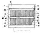
この水切部材1は、例えば図2及び図3のように、水切りバケット2の内面両側部に備えたレール21とその上に設けた押え材22との間に取付片10の挿着部101を差し込み、両側のレール21間に直交させた前後の支持片23上に取付片10及びその他端の可撓鋼棒11の開放端部側を載置して水切部材1を支持している。これを前後に配置して水切部を閉塞した沈殿物の載置部としている。
【0009】
これによると、沈殿槽等で水切りバケット2が掬い上げた砂3が水切部材1上に載置するのであるが、可撓鋼棒11が細長状のため弾性撓曲することから、図4のように、砂3の載置によって可撓鋼棒11が上下左右に自由に可撓変位するのである。
【0010】
即ち、可撓鋼棒11の一端が取付片10で固着され、その他端が支持片23上に支持された無間隙状態において、載置した砂3と掬った水の重みによって可撓鋼棒11が下側に撓んで隣接する可撓鋼棒11の間にわずかな溝ができ、また砂3の細粒が押されて可撓鋼棒11の間に入り介在することで隣接する可撓鋼棒11の間にわずかな溝ができ、これにより側方向に押された可撓鋼棒11が隣接する可撓鋼棒11によって阻止されて上下に変位するのである。
【0011】
したがって、隣接する可撓鋼棒11の間で横方向乃至斜め方向のわずかな間隙4が生じ、大部分の可撓鋼棒11の間で水切りされるのである。なお、この間隙4は、撓曲が容易なすだれ状体の開放側で多く生じて水切りが良好にできるのである。
【0012】
実験によると、分離対象とする大きさの砂3が生じた間隙4から水切りと同時に落下することがなく、砂3は間隙4に挟まれるが、水切砂の反転落下の際に可撓鋼棒11の弾性復位によって外側に弾き出されるのである。
【0013】
なお、使用が重なるにつれて生じた間隙4に砂が詰まり除去できなくなるものもあるが、該間隙4に詰まる砂は、分離対象とする大きさ以下の微細砂であり、それが詰まった状態で水切孔が確保されることから良好に水切りできるのである。したがって、間隙に詰まった砂を無理に除去する必要はないのである。即ち、微細砂の適度な詰まりによって水切りできるのであり、従来の水切孔に目詰まりして水切孔が閉塞され水切りできないこととは正反対である。
【0014】
このように本形態例によると、可撓鋼棒11を無間隙に並列させた水切部材1が、載置した砂3により撓曲されることでわずかな間隙4を生じて水切りでき、該間隙4部での目詰まりをあえて除去する必要がなく、その保守が簡単となるのである。また、ステンレス製の可撓鋼棒11の並列による水切部材1のため強度が強くて沈殿物の重量載置に耐え得るのである。
【0015】
本形態例は上記のような構成としたが、本発明においてはこれに限定されない。例えば、水切りバケットの構成及び形状は問わず、回転式の他、バケット式コンペア等の水切りバケットでもよく、その沈殿物を掬い載置する水切部材の形状や広さ等も限定されない。また、水切部材のすだれ状体を形成する可撓鋼棒の材質、断面形状、長さ等も適宜であり、細長状で弾性を有する金属製であればよく、沈殿物の種類に応じた弾性の可撓鋼棒を選択すればよい。したがって、細長い角棒体或いは細片状の可撓鋼棒でもよい。
【0016】
さらに、可撓鋼棒を1mm以下の微間隙で多数並列してもよく、沈殿物の粒径及び重量に応じて並列間隔、即ち水切り間隔を予め設けてもよい。この場合も砂の介在で可撓鋼棒間の間隙が大きくなって水切りでき、可撓鋼棒の撓曲によって水切り間隔が可変するため目詰まりすることがない。しかしながら、砂等の細粒体の水切りでは可撓鋼棒を無間隙で並列させることが最適である。
【0017】
なお、並列した可撓鋼棒の保持手段は任意であるが、夫々の可撓鋼棒の一端側で固着すれば、その他端部側の可撓が容易となって水切りが良好にできるのである。また、図5のように、可撓鋼棒の中央部で固着すればその開放側となる両端部側でのの可撓が容易となって水切りが良好にできるのである。
【0018】
【発明の効果】
本発明の請求項1によると、可撓鋼棒を多数並列させて成る水切部材が、載置した沈殿物の砂等により撓曲されることでわずかな間隙を生じ、或いは間隙が可変的に広がって水切りできるのであり、また、該間隙での目詰まりで水切溝が確保できることから目詰まりをあえて除去する必要がなく洗浄装置が不要なため安価に設備でき、その保守が簡単にできるのである。
【0019】
また請求項2では、すだれ状体と成した可撓鋼棒の夫々開放側での撓曲が容易となって水切りが良好にでき、請求項3では、水切りバケットへの取り付けが簡単にできるのである。
【図面の簡単な説明】
【図1】本発明の一形態例の斜視図である。
【図2】それを用いた水切りバケットの縦断側面図である。
【図3】それを用いた水切りバケットの平面図である。
【図4】撓曲変位した可撓鋼棒の縦断正面図である。
【図5】その別例を用いた水切りバケットの縦断側面図である。
【図6】脱水機の一部断面した側面図である。
【符号の説明】
1 水切部材
10 取付片
11 可撓鋼棒
2 水切りバケット
21 レール
22 押え材
3 砂
4 間隙[0001]
BACKGROUND OF THE INVENTION
The present invention relates to a draining member in a draining bucket for deposits such as mud sand.
[0002]
[Prior art]
Conventionally, as shown in FIG. 6, a dehydrator equipped with a draining bucket at the tip of each arm is attached to the central rotating shaft that is rotated by a motor, and the draining bucket removes the sediment in the settling tank. It scoops up and drains on the draining member, and the drained sediment is dropped and discharged by reversing the draining bucket. In addition, when draining, there is also a type of forcibly draining suction by vacuuming the lower part of the draining member of the draining bucket.
[0003]
However, conventionally, since the sediment is scooped up and mounted using a draining plate punched in a net shape, it is necessary to wash the draining plate with a cleaning device because clogging occurs gradually. Therefore, the installation of a cleaning device is required, and the equipment becomes expensive, and the cleaning work after using the draining board is required, which is troublesome.
[0004]
[Problems to be solved by the invention]
Therefore, the present inventor considers that the water drainage hole of the water drainage plate is constantly open, causing clogging, and as a result of repeated experiments with various materials, a water draining member that does not clog or can accept clogging. It has been developed, and it provides an inexpensive dehydrator by using a draining bucket that is easy to clean and does not require cleaning of the draining member.
[0005]
[Means for Solving the Problems]
For this reason, the present invention is a draining bucket of a dewatering device that scoops up sediment such as mud sand in a sedimentation tank and drains it, and drops and discharges the sediment that has been dehydrated by reversal. The drainage member in the sediment draining bucket is characterized in that a slender body made of a plurality of elongated flexible steel rods such as stainless steel having flexible elasticity is arranged in parallel with no gaps or fine gaps. In addition, a part of each flexible steel rod arranged in parallel with a small mounting piece is fixed to form a comb-like body, and the open end side of each of the mounting piece and the flexible steel rod is supported by a draining bucket body. Alternatively, the attachment piece may be fixed to one end side of the flexible steel rods arranged in parallel.
[0006]
DETAILED DESCRIPTION OF THE INVENTION
Hereinafter, details of the present invention will be described with reference to illustrated embodiments. In the embodiment of the draining
[0007]
A number of
[0008]
As shown in FIGS. 2 and 3, for example, the
[0009]
According to this, although the
[0010]
That is, in the non-gap state where one end of the
[0011]
Accordingly, a slight gap 4 in the lateral direction or the oblique direction is formed between adjacent
[0012]
According to the experiment, the
[0013]
Note that some sand clogs that cannot be removed due to clogging caused by repeated use, but the sand clogged in the gap 4 is fine sand having a size equal to or less than the size to be separated. Since the hole is secured, the water can be drained well. Therefore, it is not necessary to forcibly remove the sand clogged in the gap. That is, the water can be drained by moderate clogging of fine sand, which is the opposite of clogging the conventional water drainage hole and blocking the water drainage hole.
[0014]
As described above, according to the present embodiment, the
[0015]
Although the present embodiment is configured as described above, the present invention is not limited to this. For example, the configuration and shape of the draining bucket are not limited, and a draining bucket such as a bucket-type compare may be used in addition to the rotary type, and the shape and width of the draining member on which the sediment is placed is not limited. Moreover, the material, cross-sectional shape, length, etc. of the flexible steel rod forming the draining body of the draining member are also appropriate, and may be any elongated and elastic metal, and the elasticity corresponding to the type of precipitate A flexible steel rod may be selected. Therefore, it may be an elongated rectangular bar or a strip-like flexible steel bar.
[0016]
Further, a large number of flexible steel bars may be arranged in parallel with a minute gap of 1 mm or less, and a parallel interval, that is, a draining interval may be provided in advance according to the particle size and weight of the precipitate. Also in this case, the gap between the flexible steel bars is increased due to the sand, so that the water can be drained. However, when draining fine particles such as sand, it is optimal to have flexible steel rods juxtaposed without gaps.
[0017]
The holding means for the flexible steel rods arranged in parallel is optional, but if they are fixed on one end side of each flexible steel rod, the other end side can be easily flexible and drained well. . Further, as shown in FIG. 5, if it is fixed at the central portion of the flexible steel rod, flexibility at both end portions that are the open side becomes easy, and drainage can be satisfactorily performed.
[0018]
【The invention's effect】
According to the first aspect of the present invention, the draining member formed by arranging a large number of flexible steel rods is bent by the sand or the like of the deposited sediment, or a slight gap is generated, or the gap is variable. It is possible to spread and drain water, and since the drainage groove can be secured by clogging in the gap, it is not necessary to remove clogging and there is no need for a cleaning device, so it can be installed at low cost and its maintenance can be easily performed. .
[0019]
Further, in
[Brief description of the drawings]
FIG. 1 is a perspective view of an embodiment of the present invention.
FIG. 2 is a vertical side view of a draining bucket using the same.
FIG. 3 is a plan view of a draining bucket using the same.
FIG. 4 is a longitudinal front view of a flexible steel rod that is flexibly displaced.
FIG. 5 is a longitudinal side view of a draining bucket using another example thereof.
FIG. 6 is a side view showing a partial cross section of the dehydrator.
[Explanation of symbols]
1 Draining
Claims (3)
Priority Applications (1)
| Application Number | Priority Date | Filing Date | Title |
|---|---|---|---|
| JP02598397A JP3655984B2 (en) | 1997-01-24 | 1997-01-24 | Drainage members in drainage buckets for sediment such as sand |
Applications Claiming Priority (1)
| Application Number | Priority Date | Filing Date | Title |
|---|---|---|---|
| JP02598397A JP3655984B2 (en) | 1997-01-24 | 1997-01-24 | Drainage members in drainage buckets for sediment such as sand |
Publications (2)
| Publication Number | Publication Date |
|---|---|
| JPH10202011A JPH10202011A (en) | 1998-08-04 |
| JP3655984B2 true JP3655984B2 (en) | 2005-06-02 |
Family
ID=12180962
Family Applications (1)
| Application Number | Title | Priority Date | Filing Date |
|---|---|---|---|
| JP02598397A Expired - Lifetime JP3655984B2 (en) | 1997-01-24 | 1997-01-24 | Drainage members in drainage buckets for sediment such as sand |
Country Status (1)
| Country | Link |
|---|---|
| JP (1) | JP3655984B2 (en) |
Families Citing this family (2)
| Publication number | Priority date | Publication date | Assignee | Title |
|---|---|---|---|---|
| WO2005119780A1 (en) | 2004-06-04 | 2005-12-15 | Fujitsu Limited | Semiconductor device and process for fabricating the same |
| JP2013166299A (en) | 2012-02-15 | 2013-08-29 | Seiko Epson Corp | Liquid ejection apparatus |
-
1997
- 1997-01-24 JP JP02598397A patent/JP3655984B2/en not_active Expired - Lifetime
Also Published As
| Publication number | Publication date |
|---|---|
| JPH10202011A (en) | 1998-08-04 |
Similar Documents
| Publication | Publication Date | Title |
|---|---|---|
| JP3768518B1 (en) | Coarse / fine dust bar screen type dust remover | |
| KR102285379B1 (en) | Floating waste removal apparatus for floating waste and grit collection | |
| JP3655984B2 (en) | Drainage members in drainage buckets for sediment such as sand | |
| KR100746924B1 (en) | Screen for use of waste water treatment | |
| KR200381939Y1 (en) | Screen for use of waste water treatment | |
| JPH093858A (en) | Escalator type efficient dust collector | |
| JP3655985B2 (en) | Drainage body in sand drainage bucket | |
| EP0954651B1 (en) | Raked bar screen | |
| JP5469512B2 (en) | Dust remover | |
| JP2000265443A (en) | Dust collector | |
| KR100700383B1 (en) | Filter using for sea water | |
| KR101877854B1 (en) | Multi rake screen apparatus of chain type | |
| JP2805740B2 (en) | Dust removal equipment | |
| RU2324036C1 (en) | Sewage and storm water pre-cleaning method and device for its realisation | |
| RU36403U1 (en) | Sewage screener for the extraction of solids | |
| KR101126198B1 (en) | Screen plate for use of purifying waste water | |
| CN219547699U (en) | Drainage mechanism suitable for hydraulic engineering | |
| JP2655025B2 (en) | Dust removal device | |
| JP3239019B2 (en) | Screen movable dust remover | |
| KR102363813B1 (en) | Rotary type scraper | |
| JPH0522623U (en) | Dust removal bar screen | |
| JP3094096B2 (en) | Dust screen | |
| JPH0514216U (en) | Dust remover | |
| DE376338C (en) | Emergency exhaust system | |
| JP2685080B2 (en) | Annular screen type foreign matter treatment device |
Legal Events
| Date | Code | Title | Description |
|---|---|---|---|
| A977 | Report on retrieval |
Free format text: JAPANESE INTERMEDIATE CODE: A971007 Effective date: 20040507 |
|
| TRDD | Decision of grant or rejection written | ||
| A01 | Written decision to grant a patent or to grant a registration (utility model) |
Free format text: JAPANESE INTERMEDIATE CODE: A01 Effective date: 20050125 |
|
| A61 | First payment of annual fees (during grant procedure) |
Free format text: JAPANESE INTERMEDIATE CODE: A61 Effective date: 20050307 |
|
| R150 | Certificate of patent or registration of utility model |
Free format text: JAPANESE INTERMEDIATE CODE: R150 |
|
| FPAY | Renewal fee payment (event date is renewal date of database) |
Free format text: PAYMENT UNTIL: 20090311 Year of fee payment: 4 |
|
| FPAY | Renewal fee payment (event date is renewal date of database) |
Free format text: PAYMENT UNTIL: 20100311 Year of fee payment: 5 |
|
| FPAY | Renewal fee payment (event date is renewal date of database) |
Free format text: PAYMENT UNTIL: 20110311 Year of fee payment: 6 |
|
| FPAY | Renewal fee payment (event date is renewal date of database) |
Free format text: PAYMENT UNTIL: 20130311 Year of fee payment: 8 |