JP3655663B2 - Timing roller for transporting paper into a sheet processing machine - Google Patents
Timing roller for transporting paper into a sheet processing machine Download PDFInfo
- Publication number
- JP3655663B2 JP3655663B2 JP10229495A JP10229495A JP3655663B2 JP 3655663 B2 JP3655663 B2 JP 3655663B2 JP 10229495 A JP10229495 A JP 10229495A JP 10229495 A JP10229495 A JP 10229495A JP 3655663 B2 JP3655663 B2 JP 3655663B2
- Authority
- JP
- Japan
- Prior art keywords
- roller
- shaft
- timing roller
- paper sheet
- processing machine
- Prior art date
- Legal status (The legal status is an assumption and is not a legal conclusion. Google has not performed a legal analysis and makes no representation as to the accuracy of the status listed.)
- Expired - Fee Related
Links
Images
Classifications
-
- B—PERFORMING OPERATIONS; TRANSPORTING
- B65—CONVEYING; PACKING; STORING; HANDLING THIN OR FILAMENTARY MATERIAL
- B65H—HANDLING THIN OR FILAMENTARY MATERIAL, e.g. SHEETS, WEBS, CABLES
- B65H5/00—Feeding articles separated from piles; Feeding articles to machines
- B65H5/06—Feeding articles separated from piles; Feeding articles to machines by rollers or balls, e.g. between rollers
- B65H5/062—Feeding articles separated from piles; Feeding articles to machines by rollers or balls, e.g. between rollers between rollers or balls
-
- B—PERFORMING OPERATIONS; TRANSPORTING
- B65—CONVEYING; PACKING; STORING; HANDLING THIN OR FILAMENTARY MATERIAL
- B65H—HANDLING THIN OR FILAMENTARY MATERIAL, e.g. SHEETS, WEBS, CABLES
- B65H2511/00—Dimensions; Position; Numbers; Identification; Occurrences
- B65H2511/10—Size; Dimensions
- B65H2511/13—Thickness
Abstract
Description
【0001】
【産業上の利用分野】
本発明は、特許請求の範囲の請求項1の前提部に記載のとおりの、枚葉紙処理機械の中へ紙葉を搬送する装置に関する。
【0002】
【従来の技術】
個別紙葉用の給紙装置の場合には、紙葉パイルの最も上に来た紙葉が、前縁の領域において吸引棒によって把握され、他の紙葉から離されて、タイミングローラと搬送ローラの間に入れられ、そこから、紙葉案内装置を経て、枚葉紙処理機械の一つの胴のくわえ爪へと供給される。タイミングローラは、周期的な回転動作を行う軸上に剛性的に固定された、軸方向に延びていて一定の間隔で複数のゴムリングを担持してる1本のローラか、または複数の個別ローラである。その周期的動作自体は、タイミングローラが、紙葉を吸引棒から受け取ったときに搬送ローラの上に載り、胴のくわえ爪が紙葉を把握するや否や、搬送ローラから離される、というように行われる。この、胴のくわえ爪が紙葉を把握するや否やタイミングローラが搬送ローラから離されるということは、紙葉がくわえ爪によって自由に持ち去られ得ることを意味する。
【0003】
枚葉紙処理機械の胴への、紙葉の問題のない搬送を確実にするために、タイミングローラは、印刷機の速度よりも高い速度で作動する。紙葉がくわえ爪のストッパに追い付き得て、それにより、それらストッパで正しく揃えられるためには、この、より高い速度が必要なのである。
【0004】
最適な紙葉搬送のためには、吸引器の速度と搬送ローラの速度が、最適に相互に同期していなければならない。最適な紙葉搬送は、吸引器が、紙葉搬送方向に行われる揺動運動の間に、タイミングローラの作動領域内まで揺動し得る場合にのみ達成され得る。軸方向に延びた1本のローラを用いる場合には、このことが不可能であり、したがって、吸引器の周期的動作と、タイミングローラの周期的動作の最適な同期は断念されねばならない。
【0005】
ある印刷機においては、相異なるフォーマット、相異なる品質の紙葉が処理される。種々の要求を満たすためには、搬送ローラに対するタイミングローラの調整が可能でなければならない。軸方向に延びた1本のローラの代わりに複数の個別のローラが用いられるのであれば、それら個別のローラの、ある決まった軸方向の移動が必要とされる。このようにしてのみ、要求される速度と、要求される正確さをもっての、枚葉紙処理機械への紙葉の供給が達成され得る。
【0006】
【発明が解決しようとする課題】
本発明の目的は、でき方がどんなに異なった紙葉でも、枚葉紙処理機械への供給が保証されるような紙葉搬送装置を提供することにある。
【0007】
【課題を解決するための手段】
この目的は、本発明によれば、軸が複数の決められた位置に止め用の切り欠きを有し、各切り欠きに対応する止め機構が設けられている、ことによって構成される。
【0009】
特に簡単でコスト的に有利な一つの構造では、ばね部材が、予め決められた撓み曲線を有する一つのばね板である。このばね板の撓み曲線は、押圧力がある決まった範囲内で変えられ得るように、計算されたものである。特には、この範囲は、処理されるべき紙の種類のすべてのものが問題なしに印刷機の中に搬入されるように選択される。
【0011】
ある枚葉紙処理機械において、特に、ある印刷機においては、どんなフォーマットでも印刷される。この要求を満たすために、個々のタイミングローラが、軸上に移動可能に支持されている。タイミングローラが軸方向に位置調節され得ることは、既に印刷された紙葉が改めて枚葉紙処理機械に供給されねばならない場合には、特に大いに有利である。既に印刷された表面の損傷を避けるために、この本発明の有利な発展態様における個々のタイミングローラは、印刷のない領域に位置決めされ得る。既に前述したように、吸引器が、最適の速度で、妨害されることなくタイミングローラの作動領域に貫入するように揺動し得ることが必要である。吸引器との衝突が起こらないように、タイミングローラを位置決めすることができる。
【0012】
装置、つまりタイミングローラの(一つまたは複数)は、紙葉の供給の間には、固定装置によって軸に固定されている、一つの有利な実施態様によれば、装置のための取外し固定装置として、ねじによって軸上のノッチの中に押し込まれる1つの棒が設けられている。
【0013】
上記の固定装置の代わりに、急速締付け装置が設けられてもよい。調整用ねじを決まった調整量だけ動かすことによって、種々のタイミングローラの位置決めを、搬送ローラに対して、平行的かつ均等的に行うことができる。このことは特に重要である。なぜならば、すべてのタイミングローラの均等な押圧力の下でのみ最適な紙葉搬送が達成されるからである。調整用ねじには、例えば、調整用ねじの回転角度に、回転可能に支持されたローラの決まった高さ調整量を従属させるような、一つの目盛がつけられている。調整用ねじを所望の位置で固定するために、止め用要素、つまり、止め用ばねが設けられている。
【0014】
本発明による装置の一つの有利な発展態様によれば、ローラが、2つの軸受板の中で回転可能に支持され、ローラを支持しばね板と連続している両方の軸受板が突出部を有し、突出部は下部領域に、ローラの直径を超えて振り出している。このような構造によれば、タイミングローラが軸上で移動させられたときに、たまたま紙葉案内装置の縁に当たったとしても、ゴム被覆の損傷は回避される。
【0015】
薄い紙葉の搬送の際には特別な問題が生ずる。なぜならば、そのような紙葉は、特に高速での供給の際に、しわになる傾向があるからである。しわにならない搬送を確実にするために、本発明の一つの有利な発展態様によれば、回転可能に支持されたローラが、紙葉搬送方向に対して斜めに搬送ローラ上に載っている。このことにより、紙葉搬送方向に対して直角の方向に力が紙葉に及ぼされる。つまり、紙葉は外側に向けて引っ張られる。純構造的には、タイミングローラの斜め位置の設定は、ばね板を紙葉搬送方向に対して斜めに位置決めすることによって達成され得る。
【0016】
【実施例】
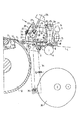
以降においては、図面を用いて本発明の実施例を詳しく説明する。図1は、ある印刷機の給紙領域の断面図が示されている。図1は特に、本発明による紙葉搬送装置1の側面図を示している。特に図示はしていない紙葉パイルの最も上の紙葉5が、軸7上に配置された吸引器6によって、前縁領域において把握され、他の紙葉から離され、軸7の揺動運動によって紙葉搬送方向に、紙葉搬送装置1のタイミングローラ8と搬送ローラ9の間に搬送される。軸7の周期的動作とタイミングローラ8の周期的動作は、吸引器6が紙葉5を、遅くとも揺動運動の反転時においては解放するように相互間で、同期されている。タイミングローラ8は、押圧力の下で搬送ローラ9上を転動し、紙葉5を、上側の紙葉案内装置3と下側の紙葉案内装置4で成る紙葉案内装置2を通し、くわえ爪のストッパ10へと押し進める。くわえ爪のストッパ10での紙葉5の正確な載り方を達成するために、紙葉5は、くわえ爪のストッパ10へと搬送され、そして膨れ上がった形になり、そこで紙葉は、くわえ爪のストッパ10に見当正しく揃えられる。くわえ爪11が紙葉の前縁を把握するや否や、タイミングローラ8は搬送ローラ9から引上げられる。したがって、くわえ爪が閉じた後には、紙葉5は完全に自由であり、機械の速度で動かされ得る。くわえ爪11とくわえ爪ストッパ10は、公知のとおり、特に図示はされていない印刷機の胴12の中に配置されている。
【0017】
紙葉搬送装置1は、二つの軸受レバー19と一つの固定用機構26,27,28によって軸33上に回転不能に固定されている。紙葉搬送装置1の主要な構成部品は、初期応力をもった一つのばね板13、一つの調整ねじ14,および軸受板15で回転可能に支持されているタイミングローラ8である。タイミングローラ8は、ゴム被覆17を担持している玉軸受16で成っている。上側の案内装置3の縁との衝突の際にゴム被覆17が損傷するのを回避するために、軸受板15は下方領域に突出部18を有している。ばね板13は、前方領域において、二つのねじ21によって軸受レバー19に連結されている。ワッシャ22がばね板13のある決まった撓み曲線を保証する。タイミングローラ8の中心点の上方で、ばね板13に一つの調整ねじ14が取り付けられている。目盛24を担持している調整ねじ23によって、タイミングローラ8の高さが、決められた大きさだけ調節される。
【0018】
前述したように、紙葉搬送装置1は、軸33の一つの止め位置において固定用機構によって固定される。この固定用機構は、軸33に設けられたノッチ28と、ちょうねじ26によってノッチ28に押し込まれる円筒形の棒27で成っている。止めボール31とナット30によって軸受レバー19上に固定された板状部品29は、タイミングローラ8の位置変えの過程において円筒形の棒27が横に外れることがないようにしている。
【0019】
印刷プロセスの開始時には、紙葉搬送装置1が、そのとき処理されるべき紙の種類に対して設定される。つまり、タイミングローラ8のゴム被覆17と搬送ローラ9の間の押圧力が、搬送されるべき紙葉5の厚さに応じて選定される。場合々々の最適な設定が、調整ねじ14の頭部23上の目盛24を用いて、問題なしに見出だされ得る。紙葉搬送装置1の周期的動作、つまり、搬送ローラ9上でのタイミングローラ8の離脱と圧着は、公知の方法で、カム制御によって行われている。このために、軸33は一つのレバー34に剛性的に結合されている。レバー34の下方領域にはローラ48が取り付けられていて、そのローラがカム36上を転動する。
【0020】
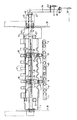
図2は、本発明による紙葉搬送装置1の配置の上面図を示している。
【0021】
下側の紙葉案内装置4が、固定手段によって、側方部材38,39と結合されている。下側の紙葉案内装置4の上に、上側の紙葉案内装置3がねじ止めされている。上側の紙葉案内装置3を清掃のために問題なしに取り外しできるように、ねじ57は、ぎざぎざ頭のねじの形にされている。上側の紙葉案内装置3は、その前方領域にも後方領域にも、切り欠き部40,41を有している。上側の紙葉案内装置3の前方領域にある切り欠き41には、くわえ爪11が噛み込む。上側の紙葉案内装置3の後方領域にある切り欠き40は、紙葉搬送装置1のタイミングローラ8のための場所を形作っている。切り欠き40の縁は、斜めになっているのが望ましい。このようにすることにより、紙葉5が縁に引っ掛かるという恐れが少なくなる。
【0022】
図1との関係で既に説明したように、紙葉搬送装置1は、軸33上に取外し可能に固定されている。各紙葉搬送装置1の位置決めは、軸33上の止め用切り欠き37で決まる複数の位置のそれぞれで行なわれる。それら複数の位置は、それら位置が別の軸7上に固定された複数の吸引器6と、隙間に入る関係になるように選定されている。このような特別な配置によって、どんな運転状態の場合でも、吸引器6とタイミングローラ8の衝突は回避されることになる。
【0023】
軸33上で紙葉搬送装置を位置変えするためには、ちょうねじ26を緩め、それに続けて、紙葉搬送装置1を、それが上側の紙葉案内装置3の部品と衝突しないように、少し揺動させることによって後方領域において持ち上げる。その紙葉搬送装置1の揺動は、軸受レバー19の前方領域にある鼻先部32によって限定されている。
【0024】
軸33の両端にある径の小さい軸ピンは、運転側では側方部材38の中で支持されている。駆動側では、軸33が側方部材39を貫通し、一つの軸受部材42の中で支持されている。軸33の軸方向の移動は、ストッパ45と位置決めリング47によって阻止されている。軸33の軸ピンは、駆動側においては、レバー34と剛性的に結合されている。レバー34の下方領域には一つのカムローラ48がねじ止めされている。レバー34は、ばね44によって、カム36の方へと引き付けられている。
【図面の簡単な説明】
【図1】 本発明による紙葉搬送装置の側面とともに、印刷機の給紙領域を示す断面図である。
【図2】 図1に示した紙葉搬送装置の配置の上面図である。
【符号の説明】
1 紙葉搬送装置
2 紙葉案内装置
3 上側の紙葉案内装置
4 下側の紙葉案内装置
5 紙葉
6 吸引器
7 軸
8 タイミングローラ
9 搬送ローラ
10 くわえ爪ストッパ
11 くわえ爪
12 胴
13 ばね板
14 調整ねじ
15 軸受板
16 玉軸受
17 ゴム被覆
18 突出部
19 軸受レバー
20 ねじ
21 ねじ
22 ワッシャ
23 調整ねじ14の頭部
24 目盛
25 止まりばね
26 ちょうねじ
27 円筒形の棒
28 ノッチ
29 板状部品
30 ナット
31 止めボール
32 鼻先部
33 軸
34 レバー
35 ボルト
36 カム
37 止め用切り欠き
38 側方部材
39 側方部材
40 切り欠き部
41 切り欠き部
42 軸受部材
43 ばね用ボルト
44 ばね
45 ストッパ
46 円板
47 位置決めリング
48 カムローラ[0001]
[Industrial application fields]
The present invention relates to an apparatus for conveying a paper sheet into a sheet processing machine as described in the premise part of claim 1.
[0002]
[Prior art]
In the case of a paper feeding device for individual paper sheets, the topmost paper sheet of the paper sheet pile is grasped by the suction bar in the area of the leading edge, separated from the other paper sheets, and conveyed with the timing roller. It is put between the rollers, and from there, it is fed to the gripper claw of one cylinder of the sheet processing machine via the paper sheet guiding device. The timing roller is a single roller that is rigidly fixed on a shaft that performs a periodic rotational operation , extends in the axial direction, and carries a plurality of rubber rings at regular intervals, or a plurality of individual rollers It is. The periodic operation itself is such that the timing roller rests on the transport roller when the paper sheet is received from the suction rod, and is released from the transport roller as soon as the gripper of the cylinder grasps the paper sheet. Done. The fact that the timing roller is separated from the conveying roller as soon as the gripping nail of the cylinder grasps the paper sheet means that the paper sheet can be freely taken away by the gripping nail.
[0003]
Sheet to the trunk of the leaf paper processing machine, in order to ensure transport without paper in question, the timing roller is operated at a higher speed than the speed of the press. This higher speed is required in order for the paper sheets to catch up with the gripper nail stoppers and thereby be properly aligned with them.
[0004]
For optimal paper sheet transport, the speed of the speed and the transport rollers of the aspirator, must be synchronous to the optimal one another. Optimal paper sheet transport is aspirator, during swinging movement takes place in the paper sheet transport direction, it can be achieved only if capable of swinging to the operating area of the timing roller. In the case of using a single roller extending in the axial direction, this is not possible, therefore, the cyclic operation of the aspirator, the optimum synchronization of the cyclic operation of the timing roller must be abandoned.
[0005]
In some printing presses, different formats and different quality sheets are processed. To meet various requirements, it must be possible to adjust the timing roller relative to the transport roller. If a plurality of individual rollers are used instead of a single axially extending roller, a certain axial movement of these individual rollers is required. Only in this way can the supply of sheets to the sheet processing machine be achieved with the required speed and the required accuracy.
[0006]
[Problems to be solved by the invention]
An object of the present invention is to provide a paper sheet conveying apparatus that guarantees the supply of a paper sheet having a different production method to a sheet processing machine.
[0007]
[Means for Solving the Problems]
This object is constituted according to the present invention in that the shaft has a notch for stopping at a plurality of predetermined positions, and a stopping mechanism corresponding to each notch is provided.
[0009]
Especially in simple and cost effective one structure, the spring member, Ru Oh at one spring plate having a predetermined deflection track line. Deflection song lines of this spring plate, as can be varied within the limits determined that there is a pressing force is that calculated. Particularly, this range is intended for all kinds of paper to be processed is selected so as to be carried into the printing press without problems.
[0011]
On some sheet processing machines, especially on some printers, any format is printed. In order to satisfy this requirement, individual timing rollers are movably supported on the shaft. The ability to adjust the timing roller in the axial direction is particularly advantageous when the already printed sheets have to be fed back into the sheet processing machine. In order to avoid damaging the already printed surface, the individual timing rollers in this advantageous development of the invention can be positioned in areas without printing. As already mentioned above, it is necessary for the aspirator to be able to oscillate at the optimum speed so as to penetrate into the working area of the timing roller without interruption. The timing roller can be positioned so that a collision with the suction device does not occur .
[0012]
Device, i.e. the timing roller (s) is between the supply of the paper, is fixed to the shaft by a fixing device, according to one advantageous embodiment, remove the fixing device for the device As such , a single rod is provided that is pushed into the notch on the shaft by a screw .
[0013]
Instead of the above-mentioned fixing device, it may be rapidly tightening device provided et been. By moving the adjusting screw by a predetermined adjustment amount, the various timing rollers can be positioned in parallel and evenly with respect to the conveying roller. This is particularly important. Why if, since only optimum paper sheet transport under uniform pressure for all of the timing roller is achieved. The adjustment screw is provided with one scale so that, for example, a predetermined height adjustment amount of the rotatably supported roller is dependent on the rotation angle of the adjustment screw. To secure the adjusting screw in the desired position, and stopper for elements, i.e., a spring for Me stop is provided.
[0014]
According to one advantageous development of the device according to the invention, the roller is rotatably supported in two bearing plates, both bearing plates which support the roller and are continuous with the spring plate have protrusions. And has a protrusion that protrudes into the lower region beyond the diameter of the roller . According to such a structure, even if the timing roller is moved on the shaft and happens to hit the edge of the paper sheet guide device, damage to the rubber coating is avoided.
[0015]
Special problems arise when transporting thin paper sheets. This is because such paper sheets tend to wrinkle, especially when fed at high speed. In order to ensure non-wrinkle transport, according to one advantageous development of the invention, the rotatably supported roller rests on the transport roller obliquely with respect to the paper sheet transport direction. As a result, a force is exerted on the paper sheet in a direction perpendicular to the paper sheet conveyance direction. That is, the paper sheet is pulled outward. Purely, the setting of the oblique position of the timing roller can be achieved by positioning the spring plate obliquely with respect to the paper sheet conveyance direction.
[0016]
【Example】
Hereinafter, embodiments of the present invention will be described in detail with reference to the drawings. Figure 1 is a cross-sectional view of the paper feed area of a printing press shown. FIG. 1 particularly shows a side view of a paper sheet transport device 1 according to the invention. In particular, the uppermost sheet 5 of the sheet pile (not shown) is grasped in the leading edge region by the suction device 6 disposed on the
[0017]
The paper sheet conveying device 1 is fixed on the
[0018]
As described above, the paper sheet conveying device 1 is fixed by the fixing mechanism in one and stopper position of the
[0019]
At the start of the printing process, the paper sheet transport device 1 is set for the type of paper to be processed at that time. That is, the pressing force between the rubber coating 17 of the timing roller 8 and the transport roller 9 is selected according to the thickness of the paper sheet 5 to be transported. If s s optimal settings, using the scale 24 on the
[0020]
FIG. 2 shows a top view of the arrangement of the paper sheet transport device 1 according to the present invention.
[0021]
The lower paper sheet guide device 4 is coupled to the
[0022]
As already described in relation to FIG. 1, the paper sheet transport device 1 is detachably fixed on the
[0023]
To reposition the paper sheet transport unit on the
[0024]
The small-diameter shaft pins at both ends of the
[Brief description of the drawings]
FIG. 1 is a cross-sectional view showing a sheet feeding area of a printing press along with a side surface of a paper sheet conveying apparatus according to the present invention .
FIG. 2 is a top view of the arrangement of the paper sheet transport device shown in FIG .
[Explanation of symbols]
1 paper sheet conveying device 2 paper
Claims (6)
前記軸(33)が複数の決められた位置に止め用の切り欠き(37)を有し、前記装置に、各切り欠きに対応する止め機構(31)が設けられていることを特徴とする、枚葉紙処理機械において紙葉を搬送する装置。It has at least one timing roller (8) that can be pressed onto one transport roller (9) with an adjustable pressing force and is rotatably supported. The timing roller (8) is a spring member (13). The sheet (5) is conveyed in the sheet processing machine, which is provided at the end of the sheet processing machine and is provided so as to be movable in the axial direction on one shaft (33) that performs periodic reciprocating rotation. In the device to
Characterized in that the shaft (33) is a notch for stopper plate in a position with a predetermined plurality have a (37), the said device, and stopper mechanisms corresponding to each notch (31) is provided An apparatus for conveying paper sheets in a sheet processing machine.
Applications Claiming Priority (2)
| Application Number | Priority Date | Filing Date | Title |
|---|---|---|---|
| DE4414445A DE4414445A1 (en) | 1994-04-26 | 1994-04-26 | Tacting roll for transporting sheets into a sheet processing machine |
| DE4414445/8 | 1994-04-26 |
Publications (2)
| Publication Number | Publication Date |
|---|---|
| JPH07309473A JPH07309473A (en) | 1995-11-28 |
| JP3655663B2 true JP3655663B2 (en) | 2005-06-02 |
Family
ID=6516414
Family Applications (1)
| Application Number | Title | Priority Date | Filing Date |
|---|---|---|---|
| JP10229495A Expired - Fee Related JP3655663B2 (en) | 1994-04-26 | 1995-04-26 | Timing roller for transporting paper into a sheet processing machine |
Country Status (5)
| Country | Link |
|---|---|
| US (1) | US5641159A (en) |
| EP (1) | EP0679593B1 (en) |
| JP (1) | JP3655663B2 (en) |
| AT (1) | ATE156775T1 (en) |
| DE (2) | DE4414445A1 (en) |
Families Citing this family (3)
| Publication number | Priority date | Publication date | Assignee | Title |
|---|---|---|---|---|
| US7334790B2 (en) * | 2004-10-29 | 2008-02-26 | Heidelberger Druckmaschinen Ag | Apparatus for conveying sheets through a rotary press |
| US7653533B2 (en) * | 2005-10-24 | 2010-01-26 | Lg Electronics Inc. | Removing time delays in signal paths |
| DE102007005404A1 (en) * | 2007-02-03 | 2008-08-07 | Man Roland Druckmaschinen Ag | Sheet guiding device for managing clocked sheet transfer in area of feeder of e.g. sheet-fed printing press, has sensor device provided for generating sensor signal indicative with respect to contact pressure applied on sheet |
Family Cites Families (14)
| Publication number | Priority date | Publication date | Assignee | Title |
|---|---|---|---|---|
| US1910506A (en) * | 1930-02-21 | 1933-05-23 | Spiess Georg | Method of and means for feeding sheets to machines |
| DE545921C (en) * | 1930-04-02 | 1932-03-07 | E H Georg Spiess Dr Ing | Device for separating and feeding individual sheets from a stack to a printing press, folding machine or the like. |
| DE830655C (en) * | 1950-09-15 | 1952-02-07 | Walter Fischer | Control of the swab rolls on sheet feeders for printing machines |
| US3210074A (en) * | 1962-04-30 | 1965-10-05 | Fairchild Camera Instr Co | Pullout feed roller for printing press |
| JPS4941642B1 (en) * | 1968-12-25 | 1974-11-11 | ||
| US3993302A (en) * | 1970-07-30 | 1976-11-23 | Miller Printing Machinery Co. | Apparatus for registering and feeding sheets to a sheet fed printing press |
| CA940148A (en) * | 1970-07-30 | 1974-01-15 | Miller Printing Machinery Co. | Apparatus for registering and feeding sheets to a sheet fed printing press |
| DD101641A1 (en) * | 1973-02-19 | 1973-11-12 | ||
| DD123801A1 (en) * | 1975-07-15 | 1977-01-19 | ||
| US4163550A (en) * | 1977-08-10 | 1979-08-07 | Am International, Inc. | Pressure roller assembly |
| JPS58181536U (en) * | 1982-05-31 | 1983-12-03 | リョービ株式会社 | Double-sided printing machine paper feed device |
| DE3731216A1 (en) * | 1987-09-17 | 1989-04-13 | Koenig & Bauer Ag | DEVICE FOR FEEDING SHEETS TO A SHEET PROCESSING MACHINE, IN PARTICULAR PRINTING MACHINE |
| US4951062A (en) * | 1988-12-12 | 1990-08-21 | Page Jeffrey L | Paper transport mechanism |
| US4979730A (en) * | 1989-11-14 | 1990-12-25 | Pitney Bowes Inc. | Sheet drive system having an encoder apparatus |
-
1994
- 1994-04-26 DE DE4414445A patent/DE4414445A1/en not_active Withdrawn
-
1995
- 1995-03-29 AT AT95104641T patent/ATE156775T1/en not_active IP Right Cessation
- 1995-03-29 EP EP95104641A patent/EP0679593B1/en not_active Expired - Lifetime
- 1995-03-29 DE DE59500495T patent/DE59500495D1/en not_active Expired - Fee Related
- 1995-04-26 JP JP10229495A patent/JP3655663B2/en not_active Expired - Fee Related
- 1995-04-26 US US08/429,065 patent/US5641159A/en not_active Expired - Fee Related
Also Published As
| Publication number | Publication date |
|---|---|
| DE59500495D1 (en) | 1997-09-18 |
| JPH07309473A (en) | 1995-11-28 |
| ATE156775T1 (en) | 1997-08-15 |
| US5641159A (en) | 1997-06-24 |
| EP0679593A1 (en) | 1995-11-02 |
| EP0679593B1 (en) | 1997-08-13 |
| DE4414445A1 (en) | 1995-11-09 |
Similar Documents
| Publication | Publication Date | Title |
|---|---|---|
| US7909454B2 (en) | Inkjet printing press | |
| JP3790563B2 (en) | Device for guiding the printing plate | |
| JP3339515B2 (en) | Paper transport device for sheet-fed printing press | |
| EP3249473B1 (en) | Electro-photographic sheet of paper duplex printing machine | |
| JP3655663B2 (en) | Timing roller for transporting paper into a sheet processing machine | |
| US3955494A (en) | Device for preventing an image of a printing master from being printed in an inclined position | |
| CA2000730C (en) | Device for correcting the register of sheet prints in a sheet-fed rotary printing machine | |
| JP3670330B2 (en) | Sheet paper conveyance device to the impression cylinder of the rotary printing device of the supplied paper | |
| JP3388005B2 (en) | Leading edge stopper and sheeting board for aligning sheets on the sheeting board | |
| JPH0144616B2 (en) | ||
| CZ380198A3 (en) | Suction catcher for transferring sheet edge in turning mechanism of sheet-fed rotary | |
| CN1028979C (en) | Device for transferring individual sheets to impression cylinder of sheet-fed rotary printing machine | |
| JPS60219057A (en) | Paper discharger | |
| JPH11263483A (en) | Method for removing pulsative register error in paper sheet rotary press and device for implementing this method | |
| US5287809A (en) | Method and device for feeding, aligning and holding a sheet on a sheet-processing machine | |
| JP2002225228A (en) | Paper presser of swing type | |
| US5265866A (en) | Device for feeding and further processing printing material in sheet-fed rotary printing presses | |
| US5454558A (en) | Side lay device | |
| JPS63231938A (en) | Device for carrying sheet printed by printer by chain transfer mechanism | |
| US4202266A (en) | Staging mechanism for duplexing copy machines | |
| JPH10316276A (en) | Paper carrying device | |
| US3552745A (en) | Rotary transfer mechanism for printing machines | |
| US6616137B2 (en) | Adjustable needles for a sheet separating device | |
| JPH10250882A (en) | Paper feeding device of sheet printer | |
| JP3454800B2 (en) | Paper feed tray |
Legal Events
| Date | Code | Title | Description |
|---|---|---|---|
| A131 | Notification of reasons for refusal |
Free format text: JAPANESE INTERMEDIATE CODE: A131 Effective date: 20040929 |
|
| A521 | Request for written amendment filed |
Free format text: JAPANESE INTERMEDIATE CODE: A523 Effective date: 20050104 |
|
| TRDD | Decision of grant or rejection written | ||
| A01 | Written decision to grant a patent or to grant a registration (utility model) |
Free format text: JAPANESE INTERMEDIATE CODE: A01 Effective date: 20050208 |
|
| A61 | First payment of annual fees (during grant procedure) |
Free format text: JAPANESE INTERMEDIATE CODE: A61 Effective date: 20050304 |
|
| R150 | Certificate of patent or registration of utility model |
Free format text: JAPANESE INTERMEDIATE CODE: R150 |
|
| LAPS | Cancellation because of no payment of annual fees |