JP3655498B2 - Tilt hinge for office automation equipment - Google Patents
Tilt hinge for office automation equipment Download PDFInfo
- Publication number
- JP3655498B2 JP3655498B2 JP16234899A JP16234899A JP3655498B2 JP 3655498 B2 JP3655498 B2 JP 3655498B2 JP 16234899 A JP16234899 A JP 16234899A JP 16234899 A JP16234899 A JP 16234899A JP 3655498 B2 JP3655498 B2 JP 3655498B2
- Authority
- JP
- Japan
- Prior art keywords
- body mounting
- mounting plate
- bearing portion
- main body
- apparatus main
- Prior art date
- Legal status (The legal status is an assumption and is not a legal conclusion. Google has not performed a legal analysis and makes no representation as to the accuracy of the status listed.)
- Expired - Fee Related
Links
Images


Description
【0001】
【発明の属する技術分野】
本発明は、パソコン、ワープロ等のOA機器のディスプレー体を開閉させるためのOA機器用チルトヒンジに関する。
【0002】
【従来の技術】
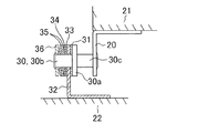
従来のOA機器用チルトヒンジの1例を図5により説明する。回転シャフト30は、大径部30aの一方側に形成された小径よりなる軸受部30bと、大径部30aの他方側に形成されたディスプレー体取付け部30cとを有している。軸受部30bには、大径部30aから順次回転摩擦板31、装置本体取付け板32、回転摩擦板33,34、スプリングワッシャ35及びスペーサ36が挿入され、軸受部30bの端部をかしめて装置本体取付け板32の両側に回転摩擦板31、33を圧接させている。ディスプレー体取付け部30cは保持板20を介してディスプレー体21に固定され、装置本体取付け板32は装置本体22に固定されている。
【0003】
この種のOA機器用チルトヒンジとして、例えば実開平5−21079号公報、実開平5−21080号公報、特開平7−324552号公報、特開平10−280781号公報等が挙げられる。
【0004】
【発明が解決しようとする課題】
上記従来技術は、軸受部30bは丸形状で、回転摩擦板31、33、34は丸穴となっている。このため、回転シャフト30を回転させた時、回転摩擦板31、33が回転シャフト30と共に回転しない場合があり、装置本体取付け板32と回転摩擦板31、33間に所定のトルクが得られないという問題があった。
【0005】
この問題を解決するものとして、軸受部30bに溝又はフラット面を設け、回転摩擦板31、33、34の穴に前記溝に係合する突起又は前記フラット面に対応したフラット面を設け、回転シャフト30と共に回転摩擦板31、33、34が回転するようにしたものが提供されている。しかし、この構造は、軸受部30bに溝又はフラット面を設けるので、強度的に軸受部30bを小さくすることができなく、大型化する。また小型化すると装置本体取付け板32と回転摩擦板31、33との接触面積が小さくなり、高トルクが得られないという問題があった。
【0006】
本発明の課題は、小型で高トルクが得られるOA機器用チルトヒンジを提供することにある。
【0007】
【課題を解決するための手段】
上記課題を解決するための本発明の手段は、大径部の端部に小径の軸受部を有し、ディスプレー体の支持部を兼ねる回転シャフトと、この回転シャフトの軸受部を回転可能に支持し、装置本体に固定される装置本体取付け板と、この装置本体取付け板の両側に圧接するように前記軸受部に挿入され、前記回転シャフトを任意の位置に面摩擦によって保持させる回転摩擦板とを少なくとも備えたOA機器用チルトヒンジにおいて、前記回転シャフトの軸受部は九角形状よりなり、前記回転摩擦板は、軸受部と共に回転するように該軸受部と同じ形状の九角形穴となっており、前記装置本体取付け板及び前記装置本体取付け板の両側に配設された前記回転摩擦板の一方の対向面には、油を保持するための波形の油溝が内周部から外周部、外周部から内周部に向けて連続して形成されていることを特徴とする。
【0009】
【発明の実施の形態】
本発明の一実施の形態を図1及び図2により説明する。図1に示すように、回転シャフト1は、大径部1aの一方側に形成された小径よりなる軸受部1bと、大径部1aの他方側に形成されたディスプレー体取付け部1cとを有している。軸受部1bには、大径部1aから順次回転摩擦板2、装置本体取付け板3、回転摩擦板4、固定摩擦板5、回転摩擦板6、スプリングワッシャ7及びスペーサ8が挿入され、軸受部1bの端部をかしめて装置本体取付け板3の両側に回転摩擦板2、4を圧接させている。ディスプレー体取付け部1cは保持板20を介してディスプレー体21に固定され、装置本体取付け板3は装置本体22に固定されている。
【0010】
軸受部1bは、図2に示すように九角形状となっている。回転摩擦板2、4、6は、軸受部1bと共に回転するように、該軸受部1bと同じ九角形穴となっている。装置本体取付け板3及び固定摩擦板5は、軸受部1bを回転可能に支持する丸穴が形成されている。また装置本体取付け板3には係合穴3aが形成され、この係合穴3aには固定摩擦板5に形成された係合突起5aが係合している。
【0011】
これにより、回転シャフト1は、所定の回転トルクを加えた時のみに回転することができ、ディスプレー体21を任意の位置で停止させることができる。装置本体取付け板3の両面には、図3に示すように、波形の油溝3bが内周部から外周部、外周部から内周部に向けて連続して形成されている。
【0012】
このように、軸受部1bは九角形状よりなり、この軸受部1bと共に回転する回転摩擦板2、4、6も九角形穴となっているので、次のような効果が得られる。軸受部1bを小径とすることができ、また装置本体取付け板3及び固定摩擦板5と接触する回転摩擦板2、4の接触面積が増大し、高トルクが得られる。更に軸受部1bの九角形状と回転摩擦板2、4、6の九角形穴との接触は、3個の三角形状と3個の三角形穴との組合せとなるので、回転シャフト1を安定して回転させることができる。
【0013】
またディスプレー体21の開閉によって回転シャフト1、回転摩擦板2、4、6が回転すると、装置本体取付け板3の油溝3b内の油は該油溝3bに沿って移動する。即ち、油は装置本体取付け板3の内周部から外周部、外周部から内周部に移動する。このため、回転摩擦板2、4のほぼ全面に対応して油が移動しながら供給されることになるので、装置本体取付け板3と回転摩擦板2、4との摩擦が低減し、耐久性が向上する。
【0014】
図4は本発明の他の実施の形態を示す。前記実施の形態は、大径部1aと装置本体取付け板3間に回転摩擦板2のみを設けた。本実施の形態は、大径部1aと装置本体取付け板3間に固定摩擦板10と、この固定摩擦板10の両側に回転摩擦板11、12を設けた。その他は前記実施の形態と同じ構成となっている。固定摩擦板10は固定摩擦板5と同様に軸受部1bを回転可能に支持する丸穴が形成され、装置本体取付け板3の係合穴3aに固定摩擦板10に形成した係合突起10aが係合している。回転摩擦板11、12は、回転摩擦板2、4、6と同様に九角形穴となっている。
【0015】
このように、固定摩擦板10及び回転摩擦板11、12を設けると、前記実施の形態と同様に効果が得られると共に、トルクは更に向上する。
【0016】
なお、上記各実施の形態においては、装置本体取付け板3に油溝3bを設けた場合について説明したが、装置本体取付け板3には油溝3bは設けないで、回転摩擦板2、4の装置本体取付け板3への対向面に前記油溝3bと同じ形状の油溝を設けてもよい。また軸受部1b及びディスプレー体取付け部1cの端部をかしめた場合について説明したが、軸受部1b及びディスプレー体取付け部1cの端部にねじ部を設け、このねじ部にナットを締め付けてもよいことは言うまでもない。
【0017】
【発明の効果】
本発明は、回転シャフトの軸受部は九角形状よりなり、回転摩擦板は、軸受部と共に回転するように該軸受部と同じ形状の九角形穴となっているので、小型で高トルクが得られる。
また前記装置本体取付け板及び前記装置本体取付け板の両側に配設された前記回転摩擦板の一方の対向面には、油を保持するための波形の油溝が内周部から外周部、外周部から内周部に向けて連続して形成されているので、油溝内の油は装置本体取付け板の内周部から外周部、外周部から内周部に移動する。このため、回転摩擦板のほぼ全面に対応して油が移動しながら供給されることになり、装置本体取付け板と回転摩擦板との摩擦が低減し、耐久性が向上する。
【図面の簡単な説明】
【図1】本発明のOA機器用チルトヒンジの一実施の形態を示す断面図である。
【図2】図1のA−A線断面拡大図である。
【図3】装置本体取付け板を示し、(a)は正面拡大図、(b)は断面拡大図である。
【図4】本発明のOA機器用チルトヒンジの他の実施の形態を示す断面図である。
【図5】従来のOA機器用チルトヒンジを示す断面図である。
【符号の説明】
1 回転シャフト
1a 大径部
1b 軸受部
1c ディスプレー体取付け部
2 回転摩擦板
3 装置本体取付け板
3b 油溝
4 回転摩擦板
5 固定摩擦板
6 回転摩擦板
10 固定摩擦板
11,12 回転摩擦板
21 ディスプレー体
22 装置本体[0001]
BACKGROUND OF THE INVENTION
The present invention relates to a tilt hinge for OA equipment for opening and closing a display body of OA equipment such as a personal computer and a word processor.
[0002]
[Prior art]
An example of a conventional tilt hinge for office automation equipment will be described with reference to FIG. The rotating shaft 30 has a bearing portion 30b having a small diameter formed on one side of the
[0003]
Examples of this type of tilt hinge for office automation equipment include Japanese Utility Model Laid-Open No. 5-21079, Japanese Utility Model Laid-Open No. 5-21080, Japanese Patent Application Laid-Open No. 7-324552, Japanese Patent Application Laid-Open No. 10-280781, and the like.
[0004]
[Problems to be solved by the invention]
In the above prior art, the bearing portion 30b has a round shape, and the
[0005]
As a solution to this problem, a groove or flat surface is provided in the bearing portion 30b, and a protrusion engaging with the groove or a flat surface corresponding to the flat surface is provided in the hole of the rotating
[0006]
An object of the present invention is to provide a tilt hinge for office automation equipment which is small and can obtain high torque.
[0007]
[Means for Solving the Problems]
Hand stage of the present invention to solve the above problems, has a bearing portion of the small-diameter end of the large diameter portion, and a rotary shaft which also serves as a supporting portion of the display body, rotatably bearing portion of the rotating shaft An apparatus main body mounting plate that is supported and fixed to the apparatus main body, and a rotating friction plate that is inserted into the bearing portion so as to be in pressure contact with both sides of the apparatus main body mounting plate and holds the rotating shaft at an arbitrary position by surface friction In the tilt hinge for office automation equipment, the bearing portion of the rotary shaft has a hexagonal shape, and the rotary friction plate is a hexagonal hole having the same shape as the bearing portion so as to rotate together with the bearing portion. On one opposing surface of the device main body mounting plate and the rotating friction plate disposed on both sides of the device main body mounting plate, a corrugated oil groove for holding oil is provided from the inner peripheral portion to the outer peripheral portion, Peripheral part Characterized in that it is formed continuously toward the inner periphery.
[0009]
DETAILED DESCRIPTION OF THE INVENTION
An embodiment of the present invention will be described with reference to FIGS. As shown in FIG. 1, the
[0010]
The
[0011]
Thereby, the rotating
[0012]
As described above, the
[0013]
When the rotating
[0014]
FIG. 4 shows another embodiment of the present invention. In the embodiment, only the rotating
[0015]
As described above, when the
[0016]
In each of the above embodiments, the case where the
[0017]
【The invention's effect】
In the present invention, the bearing portion of the rotating shaft has a hexagonal shape, and the rotating friction plate is a nine-sided hole having the same shape as the bearing portion so as to rotate together with the bearing portion. It is done.
Also, on one opposing surface of the apparatus main body mounting plate and the rotating friction plate disposed on both sides of the apparatus main body mounting plate, a corrugated oil groove for holding oil is formed from the inner periphery to the outer periphery, The oil in the oil groove moves from the inner peripheral portion of the apparatus main body mounting plate to the outer peripheral portion and from the outer peripheral portion to the inner peripheral portion. For this reason, the oil is supplied while moving substantially corresponding to the entire surface of the rotating friction plate, the friction between the apparatus main body mounting plate and the rotating friction plate is reduced, and the durability is improved.
[Brief description of the drawings]
FIG. 1 is a cross-sectional view showing an embodiment of a tilt hinge for office automation equipment according to the present invention.
FIG. 2 is an enlarged cross-sectional view taken along line AA in FIG.
3A and 3B show an apparatus main body mounting plate, where FIG. 3A is an enlarged front view and FIG. 3B is an enlarged cross-sectional view.
FIG. 4 is a cross-sectional view showing another embodiment of a tilt hinge for office automation equipment according to the present invention.
FIG. 5 is a cross-sectional view showing a conventional tilt hinge for OA equipment.
[Explanation of symbols]
DESCRIPTION OF
Claims (1)
Priority Applications (1)
| Application Number | Priority Date | Filing Date | Title |
|---|---|---|---|
| JP16234899A JP3655498B2 (en) | 1999-06-09 | 1999-06-09 | Tilt hinge for office automation equipment |
Applications Claiming Priority (1)
| Application Number | Priority Date | Filing Date | Title |
|---|---|---|---|
| JP16234899A JP3655498B2 (en) | 1999-06-09 | 1999-06-09 | Tilt hinge for office automation equipment |
Publications (2)
| Publication Number | Publication Date |
|---|---|
| JP2000346047A JP2000346047A (en) | 2000-12-12 |
| JP3655498B2 true JP3655498B2 (en) | 2005-06-02 |
Family
ID=15752861
Family Applications (1)
| Application Number | Title | Priority Date | Filing Date |
|---|---|---|---|
| JP16234899A Expired - Fee Related JP3655498B2 (en) | 1999-06-09 | 1999-06-09 | Tilt hinge for office automation equipment |
Country Status (1)
| Country | Link |
|---|---|
| JP (1) | JP3655498B2 (en) |
Families Citing this family (4)
| Publication number | Priority date | Publication date | Assignee | Title |
|---|---|---|---|---|
| KR20040027213A (en) * | 2002-09-27 | 2004-04-01 | 피케이텍시스템 주식회사 | Hinge device |
| JP4373852B2 (en) * | 2004-05-31 | 2009-11-25 | スガツネ工業株式会社 | Hinge device |
| JP2008020033A (en) * | 2006-07-14 | 2008-01-31 | Kato Electrical Mach Co Ltd | Tilt hinge and electronic equipment |
| CN113280034B (en) * | 2020-02-19 | 2022-07-22 | 苏州佳世达光电有限公司 | Rotating shaft module, electronic device bracket and electronic device |
Family Cites Families (5)
| Publication number | Priority date | Publication date | Assignee | Title |
|---|---|---|---|---|
| JPS6368532U (en) * | 1986-10-24 | 1988-05-09 | ||
| JP3163505B2 (en) * | 1991-06-07 | 2001-05-08 | 日本ピストンリング株式会社 | Mechanical element obtained by press-fitting a shaft into a fitting member and method for manufacturing the same |
| JPH06294414A (en) * | 1993-04-02 | 1994-10-21 | Nhk Spring Co Ltd | Shaft locking device |
| JPH07145837A (en) * | 1993-11-25 | 1995-06-06 | Mitsubishi Materials Corp | Facing material and its manufacture |
| JP3281570B2 (en) * | 1997-04-02 | 2002-05-13 | 株式会社やまと商社 | Tilt hinge for OA equipment |
-
1999
- 1999-06-09 JP JP16234899A patent/JP3655498B2/en not_active Expired - Fee Related
Also Published As
| Publication number | Publication date |
|---|---|
| JP2000346047A (en) | 2000-12-12 |
Similar Documents
| Publication | Publication Date | Title |
|---|---|---|
| JP5307637B2 (en) | Hinge device | |
| KR100446902B1 (en) | The hinge structure of plane-type display device | |
| JP5274585B2 (en) | Hinge mechanism | |
| US6702396B1 (en) | Wheel cover having rotating wing plate | |
| KR100216046B1 (en) | Tilt hinge | |
| JP3655498B2 (en) | Tilt hinge for office automation equipment | |
| JP2003056547A (en) | Hinge device | |
| JP2001107941A (en) | Tilt hinge | |
| JP3381677B2 (en) | Hinge mechanism and method of using the same | |
| JP3283064B2 (en) | Tilt hinge | |
| JP2001099133A (en) | Tilt hinge | |
| JP2001032823A (en) | Tilt hinge | |
| JP3004560U (en) | Tilt hinge for OA equipment | |
| JP3011568U (en) | Tilt hinge | |
| JPH0625606Y2 (en) | Light metal rocker arm | |
| JP2008309242A (en) | Tilt hinge | |
| JPH0648021U (en) | Tilt hinge | |
| JP2556125Y2 (en) | Tilt hinge for OA equipment | |
| JP3000188U (en) | Tilt hinge for OA equipment | |
| JP3014949U (en) | caster | |
| JPH0521079U (en) | Tilt hinge for OA equipment | |
| JP2004116773A (en) | Hinge device | |
| JP3095107B2 (en) | Tilt hinge for OA equipment | |
| JPH11268815A (en) | Roller attaching structure and roller shaft fixture | |
| JPH0740792Y2 (en) | Base of task arm |
Legal Events
| Date | Code | Title | Description |
|---|---|---|---|
| A977 | Report on retrieval |
Free format text: JAPANESE INTERMEDIATE CODE: A971007 Effective date: 20040930 |
|
| A131 | Notification of reasons for refusal |
Free format text: JAPANESE INTERMEDIATE CODE: A131 Effective date: 20041213 |
|
| A521 | Written amendment |
Free format text: JAPANESE INTERMEDIATE CODE: A523 Effective date: 20050125 |
|
| TRDD | Decision of grant or rejection written | ||
| A01 | Written decision to grant a patent or to grant a registration (utility model) |
Free format text: JAPANESE INTERMEDIATE CODE: A01 Effective date: 20050223 |
|
| A61 | First payment of annual fees (during grant procedure) |
Free format text: JAPANESE INTERMEDIATE CODE: A61 Effective date: 20050303 |
|
| R150 | Certificate of patent (=grant) or registration of utility model |
Free format text: JAPANESE INTERMEDIATE CODE: R150 |
|
| FPAY | Renewal fee payment (prs date is renewal date of database) |
Free format text: PAYMENT UNTIL: 20110311 Year of fee payment: 6 |
|
| FPAY | Renewal fee payment (prs date is renewal date of database) |
Free format text: PAYMENT UNTIL: 20110311 Year of fee payment: 6 |
|
| R371 | Transfer withdrawn |
Free format text: JAPANESE INTERMEDIATE CODE: R371 |
|
| FPAY | Renewal fee payment (prs date is renewal date of database) |
Free format text: PAYMENT UNTIL: 20110311 Year of fee payment: 6 |
|
| FPAY | Renewal fee payment (prs date is renewal date of database) |
Free format text: PAYMENT UNTIL: 20110311 Year of fee payment: 6 |
|
| R360 | Written notification for declining of transfer of rights |
Free format text: JAPANESE INTERMEDIATE CODE: R360 |
|
| FPAY | Renewal fee payment (prs date is renewal date of database) |
Free format text: PAYMENT UNTIL: 20110311 Year of fee payment: 6 |
|
| R370 | Written measure of declining of transfer procedure |
Free format text: JAPANESE INTERMEDIATE CODE: R370 |
|
| FPAY | Renewal fee payment (prs date is renewal date of database) |
Free format text: PAYMENT UNTIL: 20110311 Year of fee payment: 6 |
|
| FPAY | Renewal fee payment (prs date is renewal date of database) |
Free format text: PAYMENT UNTIL: 20110311 Year of fee payment: 6 |
|
| R350 | Written notification of registration of transfer |
Free format text: JAPANESE INTERMEDIATE CODE: R350 |
|
| FPAY | Renewal fee payment (prs date is renewal date of database) |
Free format text: PAYMENT UNTIL: 20110311 Year of fee payment: 6 |
|
| R350 | Written notification of registration of transfer |
Free format text: JAPANESE INTERMEDIATE CODE: R350 |
|
| LAPS | Cancellation because of no payment of annual fees | ||
| R370 | Written measure of declining of transfer procedure |
Free format text: JAPANESE INTERMEDIATE CODE: R370 |