JP3649854B2 - Speech encoding device - Google Patents
Speech encoding device Download PDFInfo
- Publication number
- JP3649854B2 JP3649854B2 JP11900697A JP11900697A JP3649854B2 JP 3649854 B2 JP3649854 B2 JP 3649854B2 JP 11900697 A JP11900697 A JP 11900697A JP 11900697 A JP11900697 A JP 11900697A JP 3649854 B2 JP3649854 B2 JP 3649854B2
- Authority
- JP
- Japan
- Prior art keywords
- speech
- error
- spectrum
- coding
- decoding
- Prior art date
- Legal status (The legal status is an assumption and is not a legal conclusion. Google has not performed a legal analysis and makes no representation as to the accuracy of the status listed.)
- Expired - Lifetime
Links
Images
Landscapes
- Detection And Prevention Of Errors In Transmission (AREA)
- Transmission Systems Not Characterized By The Medium Used For Transmission (AREA)
Abstract
Description
【0001】
【発明の属する技術分野】
本発明は、ディジタル携帯電話等のディジタル移動通信端末に使用される音声符号化装置に関する。
【0002】
【従来の技術】
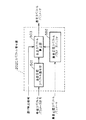
従来、誤り訂正機能を有する音声符号化装置としては、例えば、 Channel Coding For Digital Speech Transmission In Japanese Digital Cellular System (by M.J.McLaughlin, 電子情報通信学会・無線通信システム研究会、RCS90−27)に記載されたものが知られている。図9は従来の音声符号化装置の構成を示している。符号化側(a)において、901は音声符号器であり、入力音声に対し音声符号化を行い符号化パラメータを出力する。902は誤り訂正符号化器であり、符号化パラメータに対して誤り訂正符号化および誤り検出符号算出を行なう。復号側(b)において、903は誤り訂正・誤り検出器であり、受信データに対して誤り訂正および誤り検出を行なう。904は音声パラメータ補間器であり、誤り訂正後の音声符号化パラメータおよび誤り検出情報から誤り検出時の音声符号化パラメータの補間を行なう。905は音声復号器であり、音声符号化パラメータから音声復号を行なう。
【0003】
【発明が解決しようとする課題】
しかしながら、上記従来の音声符号化装置では、伝送路のビット誤りが多く、誤り訂正によって訂正しきれない誤りの検出が連続的に生じた場合、音声パラメータ補間器による音声符号化パラメータの補間が連続し、徐々に出力信号をミュートするように処理されるため、特にフェージング周波数の低い無線伝送路においては、長区間にわたり出力信号の途切れが発生し、聴感上の劣化を生じるという問題を有していた。
【0004】
本発明は、上記従来の問題を解決するもので、連続的な誤り検出区間において受信した音声符号化パラメータの一部を用いて快適雑音を生成し、途切れ感なく復号音声を再生することにより聴感的な劣化を抑えるとともに、誤り区間中においても、受信された音声情報を低品質ながら再生することのできる優れた音声符号化装置を提供することを目的とする。
【0005】
【課題を解決するための手段】
上記問題を解決するために本発明は、連続的な誤り検出区間においては、その区間で受信した音声符号化パラメータの一部、特にスペクトルパラメータを用いて快適雑音を生成し、その快適雑音信号を復号音声信号の代わりに出力するようにしたものである。また、通常の音声符号化器と誤り訂正符号化器を備えた構成に加え、誤り耐性の高い音声符号化器を並列に備え、復号側で通常の音声符号化器の符号化パラメータに対して誤り検出された場合に、並列に備えた誤り耐性の高い音声復号器の出力をその誤り検出区間の復号音声出力とするようにしたものである。
【0006】
以上により、連続的な誤り検出区間においても受信したパラメータの情報を含む快適雑音信号または誤り耐性の高い音声符号器による復号音声信号を出力することにより、途切れ感なく復号音声を再生して聴感的な劣化を抑えるとともに、誤り区間中においても、受信された音声情報を低品質ながら再生することができる。
【0007】
【発明の実施の形態】
本発明の請求項1に記載の発明は、符号化側に、入力音声に対して音声符号化を行い音声符号化パラメータを出力する音声符号化器と、得られた符号化パラメータに対して誤り訂正符号化および誤り検出符号算出を行い送信データを出力する誤り訂正符号化器とを備え、復号側に、受信データに対して誤り訂正および誤り検出を行なう誤り訂正・誤り検出器と、誤り訂正後の音声符号化パラメータから音声復号を行なう音声復号器と、誤り検出区間に対して音声符号化パラメータの一部を用いて快適雑音を生成する快適雑音生成器とを備えたものであり、誤り検出が連続する区間において、その誤り検出区間の受信音声符号化パラメータの一部を用いて快適雑音を生成しその区間の出力信号として出力することにより、連続誤り検出区間中においても、受信された音声情報を低品質ながら再生できかつ、聴感的な劣化要因である途切れ感をなくすことができるという作用を有する。
【0008】
また、本発明の請求項2に記載の発明は、請求項1に記載の発明において、符号化パラメータに、少なくとも入力音声の声道情報を表すLPCパラメータ等のスペクトル情報と声帯情報に相当する音源情報とを含む構成において、復号器側の快適雑音生成器が、受信音声符号化パラメータのうちスペクトル情報を用いて音声スペクトルパラメータを復号する音声スペクトル復号部と、雑音音源を生成する雑音音源生成部と、快適雑音信号を合成して出力する合成フィルタとを備え、連続誤り検出区間において、誤り区間の受信音声スペクトル情報の全てまたは一部を用いて合成フィルタを構成し、それを用いて快適雑音を生成しその区間の出力信号として出力することにより、連続誤り検出区間中においても、受信された音韻情報を低品質ながら再生できかつ、聴感的な劣化要因である途切れ感をなくすことができるという作用を有する。
【0009】
また、本発明の請求項3に記載の発明は、請求項2に記載の発明において、符号化側の音声符号化器における音声スペクトルパラメータの量子化器が、1段目にスペクトルパラメータの各次数毎のスカラ量子化部を備え、2段目以降にスペクトルパラメータを複数の次数に分割してそのベクトル毎にベクトル量子化する分割ベクトル量子化部を備えた多段構成を有するものであり、復号側の誤り検出区間に対して、快適雑音生成器内のスペクトル復号部において、受信スペクトルパラメータ符号のうち、1段目のスカラ量子化符号のみを用いてスペクトルパラメータを復号することにより、低品質ながら誤りの影響をより少なくスペクトルを復号することができるという作用を有する。
【0010】
また、本発明の請求項4に記載の発明は、請求項2または3に記載の発明において、復号側の快適雑音生成器内のスペクトル復号部が、当該区間の受信スペクトルパラメータ符号からスペクトルパラメータを復号するスペクトル復号部と、白色雑音スペクトルを表すスペクトルパラメータを記憶している白色雑音スペクトルバッファと、復号スペクトルパラメータおよび白色雑音スペクトルパラメータから快適雑音信号を合成するためのスペクトルパラメータを生成する合成スペクトル算出部とを備え、誤り検出が連続する場合に合成スペクトルが白色雑音スペクトルに漸近していくように動作することにより、誤り区間においてより自然な誤り区間信号再生を行なうことができるという作用を有する。
【0011】
また、本発明の請求項5に記載の発明は、請求項2または3に記載の発明において、復号側の快適雑音生成器内のスペクトル復号部が、当該区間の受信スペクトルパラメータ符号からスペクトルパラメータを復号するスペクトル復号部と、過去の無音区間のスペクトルを表すスペクトルパラメータを記憶している無音区間スペクトルバッファと、復号スペクトルパラメータおよび無音区間スペクトルパラメータから快適雑音信号を合成するためのスペクトルパラメータを生成する合成スペクトル算出部とを備え、誤り検出が連続する場合に合成スペクトルが過去の無音区間のスペクトルに漸近していくように動作することにより、誤り区間において過去の無音区間の再生信号に類似したスペクトル特性を有する、より自然な誤り区間信号再生を行なうことができるという作用を有する。
【0012】
また、本発明の請求項6に記載の発明は、請求項2から5のいずれかに記載の発明において、復号側の快適雑音生成器内の雑音音源生成部が、無音区間の音源信号を記憶する無音区間音源信号バッファと、それを用いて雑音音源を生成する雑音音源生成部とを備え、誤り検出区間の音源信号として過去の無音区間の音源信号を用いることにより、誤り区間において過去の無音区間の再生信号に類似した音源特性を有する、より自然な誤り区間信号再生を行なうことができるという作用を有する。
【0013】
また、本発明の請求項7に記載の発明は、符号化側に、入力音声に対して第1の音声符号化を行なう第1の音声符号化器と、それにより得られた符号化パラメータに対して誤り訂正符号化および誤り検出符号算出を行なう誤り訂正符号化器と、入力音声に対して、第1の音声符号化器と比べて低品質ながら誤り耐性の高い音声符号化を実現できる第2の音声符号化器とを備え、復号側に、受信データのうち第1の音声符号化器出力に対応する受信データに対して誤り訂正および誤り検出を行なう誤り訂正・誤り検出器と、誤り訂正後の音声符号化パラメータから第1の音声符号化器に対応して音声復号を行なう第1の音声復号器と、受信データのうち第2の音声符号化器出力に対応する受信データに対して音声復号を行なう第2の音声復号器と、誤り検出の結果に応じて第1の音声復号器と第2の音声復号器からの出力を切り替えまたは加算により当該区間の出力信号として出力する加算器とを備えたものであり、誤り検出が連続する場合には第2の音声復号器からの出力を復号音声信号とすることにより、音声が途切れることなく復号音声を再生できるという作用を有する。
【0014】
また、本発明の請求項8に記載の発明は、請求項7に記載の発明において、符号化側に、入力音声から、第1の音声符号化器と比べて低品質ながら誤り耐性の高い音声符号化を実現できる第2の音声符号化器による誤り耐性の高い第2の音声符号化の復号音声信号分を減算する減算器を備えたものであり、第1の音声符号化器による第1の音声符号化を、それに先立ち行われる第2の音声符号化器による第2の音声符号化の復号音声信号分を入力音声から減算された信号に対して行なうことにより、誤り検出が連続する場合における音声の途切れ感ない復号音声の再生と低ビットレート化を両立できるという作用を有する。
【0015】
また、本発明の請求項9に記載の発明は、入力音声に対して音声符号化を行い音声符号化パラメータを出力する音声符号化手順と、得られた符号化パラメータに対して誤り訂正符号化および誤り検出符号算出を行い送信データを出力する誤り訂正符号化手順と、を少なくとも含む音声符号化プログラムと、受信データに対して誤り訂正および誤り検出を行なう誤り訂正・誤り検出手順と、誤り訂正後の音声符号化パラメータから音声復号を行なう音声復号手順と、誤り検出区間に対して音声符号化パラメータの一部を用いて快適雑音を生成する快適雑音生成手順と、を少なくとも含み、前記快適雑音生成手順が、誤り検出が連続する区間において、その誤り検出区間の受信音声符号化パラメータの一部を用いて快適雑音を生成し、その区間の出力信号として出力する手順を更に含む音声復号プログラムと、を記録したことを特徴とする磁気ディスク、光磁気ディスク、ROMカートリッジのうちのいずれかの記録媒体であり、本発明の音声符号化装置をソフトウェアで実現できるという作用を有する。
さらに、本発明の請求項10に記載の発明は、入力音声に対して第1の音声符号化を行なう第1の音声符号化手順と、前記第1の音声符号化手順により得られた符号化パラメータに対して誤り訂正符号化および誤り検出符号算出を行なう誤り訂正符号化手順と、前記入力音声に対して、前記第1の音声符号化器と比べて低品質ながら誤り耐性の高い音声符号化を実現できる第2の音声符号化手順と、を少なくとも含む音声符号化プログラムと、受信データのうち前記第1の音声符号化手順の出力に対応する受信データに対して誤り訂正および誤り検出を行なう誤り訂正・誤り検出手順と、前記誤り訂正後の音声符号化パラメータから前記第1の音声符号化手順に対応して音声復号を行なう第1の音声復号手順と、前記受信データのうち前記第2の音声符号化手順の出力に対応する受信データに対して音声復号を行なう第2の音声復号手順と、前記誤り検出の結果に応じて前記第1の音声復号手順と前記第2の音声復号手順からの出力を切り替えまたは加算により当該区間の出力信号として出力する加算手順と、を少なくとも含む音声復号プログラムと、を記録したことを特徴とする磁気ディスク、光磁気ディスク、ROMカートリッジのうちのいずれかの記録媒体であり、本発明の音声符号化装置をソフトウェアで実現できるという作用を有する。
【0016】
以下、本発明の実施の形態について図面を用いて説明する。
(実施の形態1)
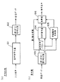
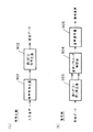
図1は本発明の請求項1に対応する音声符号化装置のブロック図を示したものである。符号側(a)において、101は入力音声に対して音声符号化を行い、音声符号化パラメータを出力する音声符号化器、102は得られた符号化パラメータに対して誤り訂正符号化および誤り検出符号算出を行い、送信データを出力する誤り訂正符号化器である。復号側(b)において、103は受信データに対して誤り訂正および誤り検出を行なう誤り訂正・誤り検出器、104は誤り訂正後の音声符号化パラメータから音声復号を行なう音声復号器、105は誤り検出区間に対して音声符号化パラメータの一部を用いて快適雑音を生成する快適雑音生成器、106は音声復号器104からの出力と快適雑音生成器105からの出力とを誤り検出情報に応じて加算する加算器である。
【0017】
以上のように構成された音声符号化装置について図1を用いてその動作を説明する。まず符号化側(a)において、一定の短区間毎に区切られた入力音声信号に対して、音声符号化器101により音声符号化を行い、音声符号化パラメータを出力する。そして得られた符号化パラメータに対して、誤り訂正符号化器102により誤り訂正符号化および誤り検出符号算出を行い送信データとして出力する。誤り訂正符号化器102では、音声符号化パラメータのうち聴感的に重要なパラメータのみに対して誤り訂正符号および誤り検出符号が計算される場合が多い。次に復号側(b)において、受信データに対して誤り訂正・誤り検出器103により誤り訂正および誤り検出を行なう。誤り検出は、誤り訂正後の受信データに誤りが残留しているかどうかを検出するもので、CRC符号がよく使用される。誤り検出の対象が聴感上重要なパラメータに限定されている場合には、その誤り検出対象のパラメータに誤りが残留しているかどうかを検出する。そして当該区間において誤り検出情報により誤りが検出されていない場合には、音声復号器104により音声復号を行い、加算器106では音声復号器104からの出力信号をそのまま復号音声として出力する。一方、誤りが検出された区間の場合、まず音声復号器104においては誤り区間補償処理を行なう。これは過去の符号化パラメータまたは復号駆動音源・復号音声等を用いて誤り区間の補償信号を生成する。但し、誤り区間が連続する場合には徐々にミュートする処理を加える。つぎに、快適雑音生成器105において、誤りを含む音声符号化パラメータの一部または全てを用いて快適雑音信号を生成する。これは、当該誤り区間の受信データから得られる音声情報の一部(例えばスペクトル情報、パワー情報など)を出力する快適雑音に反映させるように生成する。生成法は任意である。そして音声復号器104の出力の誤り区間補償信号と快適雑音生成器105出力の快適雑音信号とを加算器106にて加重加算後出力することにより誤り区間の出力信号とする。
【0018】
以上のように、本発明の実施の形態1によれば、誤り検出が連続する区間において、その誤り検出区間の受信音声符号化パラメータの一部を用いて快適雑音を生成し、その区間の出力信号として出力することにより、連続誤り検出区間中においても、受信された音声情報を低品質ながら再生でき、かつ聴感的な劣化要因である途切れ感をなくすことができる。
【0019】
(実施の形態2)
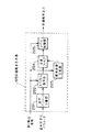
図2は本発明の請求項2に対応し、上記実施の形態1における音声符号化装置の復号側の快適雑音生成器105のブロック図を示したものである。図2において、201は受信音声符号化パラメータから各々の音声符号化パラメータに分離する音声パラメータ分離部、202は受信音声符号化パラメータうちスペクトル情報を用いて音声スペクトルパラメータを復号するスペクトル復号部、203は雑音音源を生成する雑音音源生成部、204は快適雑音信号を合成して出力する合成フィルタ、205は合成フィルタ204による合成信号に対してそのレベルを制御するレベル制御部である。
【0020】
以上のように構成された快適雑音生成器105について図2を用いてその動作を説明する。なお本実施の形態2は、符号化パラメータに少なくとも入力音声の声道情報を表すLPCパラメータ等のスペクトル情報と声帯情報に相当する音源情報とを含む音声符号化において適用できるものである。まず、音声パラメータ分離部201により受信音声符号化パラメータのうちスペクトル情報を表すスペクトルパラメータを得る。そして、スペクトル復号部202により当該受信スペクトルパラメータから音声スペクトルを復号する。音声スペクトルパラメータとしては、一般的にはLPCパラメータ(例えばLPC係数やLSPパラメータ等)がよく使用される。次に、雑音音源生成部203において快適雑音の駆動音源信号を生成する。駆動音源信号としては白色ランダム雑音等の定常雑音信号を用いる。そして、合成フィルタ204により雑音音源生成部203で得られた音源信号と、スペクトル復号部202で得られたスペクトルパラメータを用いて快適雑音信号とを合成し、レベル制御部205にて出力レベルを制御した後、出力する。
【0021】
以上のように本発明の実施の形態2によれば、連続誤り検出区間において、誤り区間の受信音声スペクトル情報の全てまたは一部を用いて合成フィルタを構成し、それを用いて快適雑音を生成しその区間の出力信号として出力することにより、連続誤り検出区間中においても、受信された音韻情報を低品質ながら再生でき、かつ聴感的な劣化要因である途切れ感をなくすことができる。
【0022】
(実施の形態3)
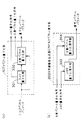
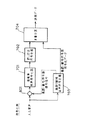
図3は本発明の請求項3に対応し、実施の形態1における音声符号化装置の符号化側の音声符号器に音声の声道情報を表すスペクトル情報を量子化するスペクトル量子化器を含む構成の場合において、そのスペクトル量子化器107と、実施の形態2における復号側の快適雑音生成器105におけるスペクトル復号部202Aのブロック図を示したものである。図3(a)において、301は音声スペクトルパラメータの量子化器におけるスペクトルパラメータの各次数毎のスカラ量子化部、302はスペクトルパラメータを複数の次数に分割してそのベクトル毎にベクトル量子化する分割ベクトル量子化部である。また図3(b)において、303は快適雑音生成器105のスペクトル復号部202Aにおいてスカラ量子化部分の復号を行なうスカラ量子化復号部、304は分割ベクトル量子化部分の復号を行なう分割ベクトル量子化復号部である。
【0023】
以上のように構成された音声符号化装置について図3を用いてその動作を説明する。まず符号化側のスペクトル量子化器107において、入力スペクトル(ベクトル)に対して、1段目のスカラ量子化部301で各次数毎のスカラ値をスカラ量子化する。次に分割ベクトル量子化部302において、2段目の量子化部として1段目の量子化誤差部分を量子化する。ここではスペクトルパラメータを複数次数毎に分割して、量子化効率の高いベクトル量子化により量子化を行なう。そしてそれぞれの量子化部での量子化符号(スカラ量子化符号、分割ベクトル量子化符号)を出力する。一方、復号側の音声復号器においても、上記と同様な構成で量子化復号器を構成してスペクトル復号する。すなわち、復号側の快適雑音生成器105におけるスペクトル復号部202Aにおいては、受信スペクトル符号のうちスカラ量子化符号のみを用いてスカラ量子化復号部303によりスカラ量子化部分のスペクトルを復号し,快適雑音のスペクトルとして出力する。
【0024】
以上のように本発明の実施の形態3によれば、符号化側のスペクトル量子化が多段構成になっており、1段目に量子化効率は落ちるもののビット誤り影響が少ないスカラ量子化を、2段目に量子化効率の高いベクトル量子化を行なう構成とし、復号側の連続誤り区間に対して、快適雑音生成器105のスペクトル復号部202Aにおいて、誤り耐性の高い1段目のスカラ量子化部分のみの復号スペクトルを快適雑音の合成スペクトルとして用いることにより、低品質ながら誤りの影響のより少ないスペクトル復号を行なうことができる。
【0025】
なお、本実施の形態3では、2段構成のスカラ量子化+ベクトル量子化という構成で示したが、3段以上の多段構成でもよい。また1段目のスカラ量子化部301を前区間の1段目の量子化結果からの差分または予測量子化を用いることにより、スカラ量子化ビット数が1ビットでかつ量子化効率を向上させることができ、より誤りの影響が少ない復号が行なえる。さらにその他の誤り耐性の高い量子化構造の量子化器を用いることも可能である。
【0026】
(実施の形態4)
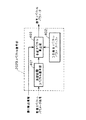
図4は本発明の請求項4に対応し、請求項2または3記載の音声符号化装置の復号側の快適雑音生成器105におけるスペクトル復号部202Bのブロック図を示したものである。図4において、401は当該区間の受信スペクトルパラメータ符号からスペクトルパラメータを復号する当該区間スペクトル復号部、402は白色雑音スペクトルを表すスペクトルパラメータを記憶している白色雑音スペクトルバッファ、403は復号スペクトルパラメータおよび白色雑音スペクトルパラメータから快適雑音信号を合成するためのスペクトルパラメータを生成する合成スペクトル算出部である。
【0027】
以上のように構成されたスペクトル復号部202Bについて図4を用いてその動作を説明する。まず当該区間スペクトル復号部401において、当該区間の受信スペクトルパラメータ符号からスペクトル復号を行なう。これは受信スペクトル符号全てを用いた復号あるいは実施の形態3において示した部分的な符号のみで復号する方法いずれでもよい。次に合成スペクトル算出部403において、当該区間スペクトル復号部401出力のスペクトルパラメータと白色雑音スペクトルバッファ402出力の白色雑音スペクトルパラメータを用いて当該区間で使用する合成スペクトルパラメータを算出する。合成スペクトルパラメータは、誤り区間が長区間にわたり連続する場合に、合成スペクトルが白色雑音スペクトルに漸近していくようなスペクトルが得られるように算出される。例えば、スペクトルパラメータとしてLSPパラメータを用いる場合、当該区間復号LSPと白色雑音LSPの線形加算を行ない、その加重係数を誤り検出の連続区間数に比例して白色雑音LSPに漸近するように制御する。他の実現方法も可能である。
【0028】
以上のように、本発明の実施の形態4によれば、誤り検出が長期間にわたり連続する場合に、合成スペクトルが白色雑音に漸近していくように動作することにより、誤り区間において、より自然な誤り区間信号再生を行なうことができる。
【0029】
(実施の形態5)
図5は本発明の請求項5に対応し、請求項2または3記載の音声符号化装置の復号側の快適雑音生成器105におけるスペクトル復号部202Cのブロック図を示したものである。図5において、501は当該区間の受信スペクトルパラメータ符号からスペクトルパラメータを復号する当該区間スペクトル復号部、502は過去の無音区間(雑音のみの区間を含む)のスペクトルを表すスペクトルパラメータを記憶している無音区間スペクトルパラメータバッファ、503は復号スペクトルパラメータおよび無音区間スペクトルパラメータから快適雑音信号を合成するためのスペクトルパラメータを生成する合成スペクトル算出部である。
【0030】
以上のように構成されたスペクトル復号部202Cについて図5を用いてその動作を説明する。まず当該区間スペクトル復号部501において、当該区間の受信スペクトルパラメータ符号からスペクトル復号を行なう。これは受信スペクトル符号全てを用いた復号あるいは実施の形態3において示した部分的な符号のみで復号する方法いずれでもよい。一方、無音区間スペクトルパラメータバッファ502は、過去の無音(音声のない区間、周囲雑音のみの区間も含む)と判定された区間の復号スペクトルパラメータを入力とし、それらを逐次的に平均化することで、無音区間の平均的なスペクトルパラメータを保持している。次に合成スペクトル算出部503において、当該区間スペクトル復号部501出力のスペクトルパラメータと無音区間スペクトルパラメータバッファ502出力の無音区間スペクトルパラメータを用いて当該区間で使用する合成スペクトルパラメータを算出する。合成スペクトルパラメータは、誤り区間が連続する場合に、合成スペクトルが無音区間スペクトルに漸近していくようなスペクトルが得られるように算出される。例えば、スペクトルパラメータとしてLSPパラメータを用いる場合、当該区間復号LSPと無音区間LSPの線形加算を行ない、その加重係数を誤り検出の連続区間数に比例して無音区間LSPに漸近するように制御する。他の実現方法も可能である。
【0031】
以上のように、本発明の実施の形態5によれば、誤り検出が長期間にわたり連続する場合に、合成スペクトルが無音区間のスペクトルに漸近していくように動作することにより、誤り区間において過去の無音区間の再生信号に類似したスペクトル特性を有する、より自然な誤り区間信号再生を行なうことができる。
【0032】
(実施の形態6)
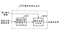
図6は本発明の請求項6に対応し、請求項2から5のいずれかに記載の音声符号化装置における復号側の快適雑音生成器105内の雑音音源生成部203のブロック図を示したものである。図6において、601は無音区間の音源信号を記憶する無音区間音源信号バッファ、602は無音区間音源信号を用いて雑音音源を生成する雑音音源生成部である。
【0033】
以上のように構成された雑音音源生成部203について図6を用いてその動作を説明する。まず無音区間音源信号バッファ601は、過去の無音(音声のない区間、周囲雑音のみの区間も含む)と判定された区間の音声復号時の駆動音源信号から、無音区間を代表する音源信号を逐次的に保持しているもので、過去の無音区間の駆動音源信号を単純に逐次的に加算したものをバッファに蓄えるか、または過去の駆動音源に対して過去の蓄積されたバッファ内の相関性の高い区間を加重加算して更新する等により、無音区間の音源特性を有する音源信号を保持する。そして、雑音音源生成部602により無音区間音源信号バッファ601からランダムに一定区間長だけ取り出すことにより雑音音源信号を生成する。
【0034】
以上のように、本発明の実施の形態6によれば、誤り検出区間の音源信号として過去の無音区間の音源信号を用いることにより、誤り区間において過去の無音区間の再生信号に類似した音源特性を有する、より自然な誤り区間信号再生を行なうことができる。
【0035】
(実施の形態7)
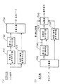
図7は本発明の請求項7に対応する音声符号化装置のブロック図を示したものである。図7において、符号化側(a)において、701は入力音声に対して低ビットレートで高能率な音声符号化を行なう高能率音声符号化器(第1の音声符号化器)、702は得られた符号化パラメータに対して誤り訂正符号化および誤り検出符号算出を行なう誤り訂正符号化器(第2の音声符号化器)、703は入力音声に対して、高能率音声符号化器701と比べて低品質ながら誤り耐性の高い音声符号化を実現できる高誤り耐性音声符号化器、704は誤り訂正符号化器702および高誤り耐性符号化器703の出力データを多重化する多重化器である。復号側(b)において、705は復号側において受信データを分離する分離器、706は受信データのうち高能率音声符号化器701出力に対応する受信データに対して誤り訂正および誤り検出を行なう誤り訂正・誤り検出器、707は誤り訂正後の音声符号化パラメータから高能率音声符号化器701に対応して音声復号を行なう高能率音声復号器(第1の音声復号器)、708は受信データのうち高誤り耐性音声符号化器703出力に対応する受信データに対して音声復号を行なう高誤り耐性音声復号器(第2の音声復号器)、709は誤り検出の結果に応じて高能率音声復号器707と高誤り耐性音声復号器708からの出力を切り替えまたは加算により当該区間の出力信号として出力する加算器である。
【0036】
以上のように構成された音声符号化装置について図7を用いてその動作を説明する。まず符号化側(a)において、入力音声に対して高能率音声符号化器701において低ビットレートで高能率な音声符号化を行なう。低ビットレートで高能率な音声符号化としてはCELP符号化が代表的である。そして、誤り訂正符号化器702により、高能率音声符号化器701で得られた符号化パラメータに対して誤り訂正符号化および誤り検出符号算出を行い、符号データを出力する。一方、それと並列して高誤り耐性音声符号化器703により、入力音声に対して低品質ながら高い誤り耐性を実現できる高誤り耐性の音声符号化を行い、誤り訂正符号化なしで符号化データを出力する。高誤り耐性の音声符号化としては、ADM符号化や入力信号のサンプル値を+1/−1の2値で表し量子化する方法等がある。いずれも低ビットレートでは復号信号の品質は低いが、ビット誤りに対する誤り耐性は高い方法である。さらに入力音声に対して帯域制限を行い、低周波数帯域のみに適用することにより、より低ビットレートで符号化が行なえる。そして、多重化器704により誤り訂正符号化器702および高誤り耐性音声符号化器703の出力データを多重化し、送信データとして出力する。次に、復号側(b)において、分離器705により高能率音声符号化器701出力に対応する受信データと高誤り耐性音声符号化器703出力に対応する受信データを分離する。そして、誤り訂正・誤り検出器706により高能率音声符号化器701出力に対応する受信データに対して誤り訂正および誤り検出を行なったのち、高能率音声復号器707により誤り訂正後の音声符号化パラメータから高能率音声符号化器701に対応して音声復号を行なう。また、高誤り耐性音声復号器708により受信データのうち高誤り耐性音声符号化器703出力に対応する受信データに対して音声復号を行なう。そして、加算器709において誤り検出の結果に応じて高能率音声復号器707と高誤り耐性音声復号器708からの出力を切り替えまたは加算により当該区間の出力信号として出力する。具体的には誤りが検出されない区間においては、高能率音声復号器707の出力をそのまま出力信号として出力し、誤り検出区間においては、高能率音声復号器707における誤り区間補償による復号信号と高誤り耐性音声復号器708の出力信号との加算信号を出力し、誤り検出が連続する場合には、高誤り耐性音声復号器708からの出力信号を出力とする。
【0037】
以上のように、本発明の実施の形態7によれば、誤り検出が連続する場合には高誤り耐性音声復号器708からの出力を復号音声信号とすることにより、音声が途切れることなく復号音声を再生できる。
【0038】
(実施の形態8)
図8は本発明の請求項8に対応し、請求項7に記載の音声符号化装置の符号化側のブロック図を示したものである。図8において、801は減算器であり、減算器801は、入力音声から、高能率音声符号化器701と比べて低品質ながら誤り耐性の高い音声符号化を実現できる高誤り耐性音声符号化器703出力の復号音声信号分を減算するものである。それ以外の構成は図7に示した実施の形態7の音声符号化装置と同様である。
【0039】
以上のように構成された音声符号化装置について図8を用いてその動作を説明する。まず符号化側において、高誤り耐性音声符号化器703により、入力音声に対して低品質ながら高い誤り耐性を実現できる高誤り耐性の音声符号化を行い、誤り訂正符号化なしで符号化データを出力するとともに、高誤り耐性音声符号器703により符号化された符号化データを用いて音声復号を行い、復号信号を出力する。そして減算器801により入力音声から高誤り耐性音声符号化器703による高誤り耐性音声符号化の復号音声信号分を減算し、その差分信号を出力する。次に、その差分信号を入力として高能率音声符号化器701において低ビットレートで高能率な音声符号化を行なう。そして、誤り訂正符号化器702により、高能率音声符号化器701で得られた符号化パラメータに対して誤り訂正符号化および誤り検出符号算出を行い、符号データを出力する。そして、多重化器704により誤り訂正符号化器702および高誤り耐性音声符号化器703の出力データを多重化して送信データとして出力する。一方、復号側は図7に示す実施の形態7の復号側と同様である。ただし、加算器709においては、誤りが検出されない区間においては高能率音声復号器707の出力信号と高誤り耐性音声復号器708の出力信号を加算して出力し、誤り検出が連続する場合には、高誤り耐性音声復号器708からの出力信号のみを出力とする。
【0040】
以上のように、本発明の実施の形態8によれば、高能率音声符号化器701による高能率音声符号化が、それに先立ち行われる高誤り耐性音声符号化器703による高誤り耐性音声符号化の復号音声信号分を入力音声から減算された信号に対して行なうことにより、誤り検出が連続する場合の音声の途切れ感ない復号音声の再生と低ビットレート化を両立させることができる。
【0041】
(実施の形態9)
本発明の実施の形態9は請求項1から8のいずれかに記載の音声符号化装置をソフトウェアで実現したプログラムを記録した磁気ディスク、光磁気ディスク、ROMカートリッジ等の記録媒体であり、本発明の音声符号化装置をソフトウェアで実現することができる。
【0042】
【発明の効果】
以上のように、本発明の請求項1記載の発明においては、誤り検出が連続する区間において、その誤り検出区間の受信音声符号化パラメータの一部を用いて快適雑音を生成しその区間の出力信号として出力することにより、連続誤り検出区間中においても、受信された音声情報を低品質ながら再生でき、かつ聴感的な劣化要因である途切れ感をなくすことができるという効果が得られる。
【0043】
また、本発明の請求項2記載の発明においては、連続誤り検出区間において、誤り区間の受信音声スペクトル情報の全てまたは一部を用いて合成フィルタを構成し、それを用いて快適雑音を生成しその区間の出力信号として出力することにより、連続誤り検出区間中においても、受信された音韻情報を低品質ながら再生でき、かつ聴感的な劣化要因である途切れ感をなくすことができるという効果が得られる。
【0044】
また、本発明の請求項3記載の発明においては、スペクトル量子化が多段構成になっており、1段目に量子化効率は落ちるもののビット誤り影響が少ないスカラ量子化を、2段目に量子化効率の高いベクトル量子化を行なう構成とし、復号側の連続誤り区間における快適雑音生成器のスペクトル復号部において、誤り耐性の高い1段目のスカラ量子化部分のみの復号スペクトルを快適雑音の合成スペクトルとして用いることにより、低品質ながら誤りの影響のより少ないスペクトル復号を行なうことができるという効果が得られる。
【0045】
また、本発明の請求項4記載の発明においては、誤り検出が長期間にわたり連続する場合に合成スペクトルが白色雑音スペクトルに漸近していくように動作することにより、誤り区間において、より自然な誤り区間信号再生を行なうことができるという効果が得られる。
【0046】
また、本発明の請求項5記載の発明においては、誤り検出が長期間にわたり連続する場合に合成スペクトルが無音区間のスペクトルに漸近していくように動作することにより、誤り区間において過去の無音区間の再生信号に類似したスペクトル特性を有する、より自然な誤り区間信号再生を行なうことができるという効果が得られる。
【0047】
また、本発明の請求項6記載の発明においては、誤り検出区間の音源信号として過去の無音区間の音源信号を用いることにより、誤り区間において過去の無音区間の再生信号に類似した音源特性を有する、より自然な誤り区間信号再生を行なうことができるという効果が得られる。
【0048】
また、本発明の請求項7記載の発明においては、誤り検出が連続する場合には高誤り耐性音声復号器(第2の音声復号器)からの出力を復号音声信号とすることにより、音声が途切れることなく復号音声を再生できるという効果が得られる。
【0049】
また、本発明の請求項8記載の発明においては、高能率音声符号化器(第1の音声符号化器)による高能率音声符号化を、それに先立ち行われる高誤り耐性音声符号化器(第2の音声符号化器)による高誤り耐性音声符号化の復号音声信号分を入力音声から減算した信号に対して行なうことにより、誤り検出が連続する場合における音声の途切れ感ない復号音声の再生と低ビットレート化を両立させることができるという効果が得られる。
【0050】
また、本発明の請求項9記載の発明は、入力音声に対して音声符号化を行い音声符号化パラメータを出力する音声符号化手順と、得られた符号化パラメータに対して誤り訂正符号化および誤り検出符号算出を行い送信データを出力する誤り訂正符号化手順と、を少なくとも含む音声符号化プログラムと、受信データに対して誤り訂正および誤り検出を行なう誤り訂正・誤り検出手順と、誤り訂正後の音声符号化パラメータから音声復号を行なう音声復号手順と、誤り検出区間に対して音声符号化パラメータの一部を用いて快適雑音を生成する快適雑音生成手順と、を少なくとも含み、前記快適雑音生成手順が、誤り検出が連続する区間において、その誤り検出区間の受信音声符号化パラメータの一部を用いて快適雑音を生成し、その区間の出力信号として出力する手順を更に含む音声復号プログラムと、を記録したことを特徴とする磁気ディスク、光磁気ディスク、ROMカートリッジのうちのいずれかの記録媒体であり、本発明の音声符号化装置をソフトウェアで実現できるという効果が得られる。
さらに、本発明の請求項10に記載の発明は、入力音声に対して第1の音声符号化を行なう第1の音声符号化手順と、前記第1の音声符号化手順により得られた符号化パラメータに対して誤り訂正符号化および誤り検出符号算出を行なう誤り訂正符号化手順と、前記入力音声に対して、前記第1の音声符号化器と比べて低品質ながら誤り耐性の高い音声符号化を実現できる第2の音声符号化手順と、を少なくとも含む音声符号化プログラムと、受信データのうち前記第1の音声符号化手順の出力に対応する受信データに対して誤り訂正および誤り検出を行なう誤り訂正・誤り検出手順と、前記誤り訂正後の音声符号化パラメータから前記第1の音声符号化手順に対応して音声復号を行なう第1の音声復号手順と、前記受信データのうち前記第2の音声符号化手順の出力に対応する受信データに対して音声復号を行なう第2の音声復号手順と、前記誤り検出の結果に応じて前記第1の音声復号手順と前記第2の音声復号手順からの出力を切り替えまたは加算により当該区間の出力信号として出力する加算手順と、を少なくとも含む音声復号プログラムと、を記録したことを特徴とする磁気ディスク、光磁気ディスク、ROMカートリッジのうちのいずれかの記録媒体であり、本発明の音声符号化装置をソフトウェアで実現できるという効果を有する。
【図面の簡単な説明】
【図1】本発明の実施の形態1における音声符号化装置の符号化側(a)と復号化側(b)のブロック図
【図2】本発明の実施の形態2の音声符号化装置の復号側における快適雑音生成器のブロック図
【図3】本発明の実施の形態3の音声符号化装置における符号側の音声符号化器のスペクトル量子化部(a)と復号側の快適雑音生成器におけるスペクトル復号部(b)のブロック図
【図4】本発明の実施の形態4の音声符号化装置の復号側の快適雑音生成器におけるスペクトル復号部のブロック図
【図5】本発明の実施の形態5の音声符号化装置の復号側の快適雑音生成器におけるスペクトル復号部のブロック図
【図6】本発明の実施の形態6の音声符号化装置における復号側の快適雑音生成器内の雑音音源生成部のブロック図
【図7】本発明の実施の形態7における音声符号化装置の符号化側(a)と復号化側(b)のブロック図
【図8】本発明の実施の形態8における音声符号化装置のブロック図
【図9】従来の音声符号化装置の符号化側(a)と復号化側(b)のブロック図
【符号の説明】
101 音声符号化器
102 誤り訂正符号化器
103 誤り訂正・誤り検出器
104 音声復号器
105 快適雑音生成器
106 加算器
201 音声パラメータ分離部
202 スペクトル復号部
203 雑音音源生成部
204 合成フィルタ
205 レベル制御部
301 スカラ量子化部
302 分割ベクトル量子化部
303 スカラ量子化復号部
304 分割ベクトル量子化復号部
401 当該区間スペクトル復号部
402 白色雑音スペクトルパラメータバッファ
403 合成スペクトル算出部
501 当該区間スペクトル復号部
502 無音区間スペクトルパラメータバッファ
503 合成スペクトル算出部
601 無音区間音源信号バッファ
602 雑音音源生成部
701 高能率音声符号化器
702 誤り訂正符号化器
703 高誤り耐性符号化器
704 多重化器
705 分離器
706 誤り訂正・誤り検出器
707 高能率音声復号器
708 高誤り耐性音声復号器
709 加算器
801 減算器
901 音声符号化器
902 誤り訂正符号化器
903 誤り訂正・誤り検出器
904 音声パラメータ補間器
905 音声復号器[0001]
BACKGROUND OF THE INVENTION
The present invention relates to a speech coding apparatus used in a digital mobile communication terminal such as a digital mobile phone.
[0002]
[Prior art]
Conventionally, a speech coding apparatus having an error correction function is described in, for example, Channel Coding For Digital Speech Transmission in Japanese Digital Cellular System (by MJ McLaughlin, IEICE / Radio Communication Systems Research Group, RCS 90-27). Is known. FIG. 9 shows the configuration of a conventional speech coding apparatus. On the encoding side (a),
[0003]
[Problems to be solved by the invention]
However, in the conventional speech coding apparatus, when there are many bit errors in the transmission path and errors that cannot be corrected by error correction occur continuously, speech parameter interpolation by the speech parameter interpolator continues. However, since processing is performed so that the output signal is gradually muted, particularly in a wireless transmission line with a low fading frequency, there is a problem in that the output signal is interrupted over a long section, resulting in deterioration in audibility. It was.
[0004]
The present invention solves the above-described conventional problems, generates comfort noise using a part of speech coding parameters received in continuous error detection sections, and reproduces decoded speech without a sense of discontinuity. An object of the present invention is to provide an excellent speech coding apparatus that can suppress received degradation and reproduce received speech information with low quality even during an error interval.
[0005]
[Means for Solving the Problems]
In order to solve the above problem, in the present invention, in a continuous error detection period, comfort noise is generated using a part of speech coding parameters received in the period, in particular, spectral parameters, and the comfort noise signal is This is output in place of the decoded audio signal. Moreover, in addition to a configuration including a normal speech coder and an error correction coder, a speech coder with high error tolerance is provided in parallel, and on the decoding side, the coding parameters of the normal speech coder When an error is detected, the output of the speech decoder with high error tolerance provided in parallel is used as the decoded speech output of the error detection section.
[0006]
As described above, by outputting a comfortable noise signal including parameter information received in a continuous error detection interval or a decoded speech signal by a speech encoder having high error tolerance, the decoded speech can be reproduced without a sense of discontinuity. In addition, the received audio information can be reproduced with low quality even during an error interval.
[0007]
DETAILED DESCRIPTION OF THE INVENTION
According to the first aspect of the present invention, a speech coder that performs speech coding on input speech and outputs speech coding parameters on the encoding side, and an error with respect to the obtained coding parameters. An error correction encoder that performs correction coding and error detection code calculation and outputs transmission data; and an error correction / error detector that performs error correction and error detection on received data on the decoding side; and error correction It includes a speech decoder that performs speech decoding from later speech coding parameters, and a comfort noise generator that generates comfort noise using part of the speech coding parameters for the error detection interval. In a continuous detection period, a comfortable noise is generated using a part of the received speech coding parameters of the error detection section and output as an output signal of the section. Can have, has the effect of the received voice information and can be played while lower quality, can be eliminated feeling interruption is perceptual deterioration factor.
[0008]
The invention according to claim 2 of the present invention is the sound source corresponding to the spectrum information such as LPC parameters representing vocal tract information of the input speech and vocal cord information as the encoding parameter in the invention according to claim 1. A comfortable noise generator on the decoder side includes a speech spectrum decoding unit that decodes a speech spectrum parameter using spectrum information among received speech coding parameters, and a noise source generation unit that generates a noise source And a synthesis filter that synthesizes and outputs a comfort noise signal. In the continuous error detection interval, a synthesis filter is configured using all or part of the received speech spectrum information in the error interval, and the comfort noise is generated using the synthesis filter. Is generated and output as the output signal of the interval, so that the received phoneme information is reduced in quality even during the continuous error detection interval. Et reproduction can and has the effect that it is possible to eliminate a sense of interruption is perceptual deterioration factor.
[0009]
The invention according to claim 3 of the present invention is the invention according to claim 2, in which the speech spectrum parameter quantizer in the speech encoder on the encoding side has each order of the spectrum parameter in the first stage. Each stage has a scalar quantization unit, and has a multi-stage configuration including a divided vector quantization unit that divides a spectrum parameter into a plurality of orders after the second stage and performs vector quantization for each vector. For the error detection interval of, the spectral decoding unit in the comfort noise generator decodes the spectral parameter using only the first-stage scalar quantization code of the received spectral parameter code, thereby reducing the error with low quality. The spectrum can be decoded with less influence.
[0010]
The invention according to claim 4 of the present invention is the invention according to claim 2 or 3, wherein the spectrum decoding unit in the comfort noise generator on the decoding side calculates the spectrum parameter from the received spectrum parameter code in the section. A spectrum decoding unit for decoding, a white noise spectrum buffer storing a spectrum parameter representing a white noise spectrum, and a combined spectrum calculation for generating a spectrum parameter for synthesizing a comfort noise signal from the decoded spectrum parameter and the white noise spectrum parameter When the error detection is continued, the operation is performed so that the combined spectrum becomes asymptotic to the white noise spectrum, so that it is possible to perform more natural error interval signal reproduction in the error interval.
[0011]
The invention according to claim 5 of the present invention is the invention according to claim 2 or 3, wherein the spectrum decoding unit in the comfort noise generator on the decoding side calculates the spectrum parameter from the received spectrum parameter code in the section. A spectrum decoding unit for decoding, a silence interval spectrum buffer storing a spectrum parameter representing a spectrum of a past silence interval, and a spectrum parameter for synthesizing a comfort noise signal from the decoded spectrum parameter and the silence interval spectrum parameter are generated. A spectrum similar to the reproduced signal of the past silent section in the error section by operating so that the combined spectrum asymptotically approaches the spectrum of the past silent section when error detection continues. Characteristic, more natural error interval signal reproduction Such an action can be performed.
[0012]
The invention according to claim 6 of the present invention is the invention according to any one of claims 2 to 5, wherein the noise source in the comfortable noise generator on the decoding side stores the source signal in the silent section. A silent sound source signal buffer for generating a noise sound source using the silent sound source signal buffer, and using a sound source signal of a past silent section as a sound source signal of an error detection section, It has the effect that more natural error interval signal reproduction can be performed with sound source characteristics similar to the reproduction signal of the interval.
[0013]
In the invention according to claim 7 of the present invention, the encoding side is adapted to the input speech.FirstPerform voice encodingFirstA speech coder, an error correction coder that performs error correction coding and error detection code calculation on the coding parameters obtained thereby, and input speechCompared to the first speech coderLow qualityWrongResistanceHigh speech codingCan be realizedSecond voiceAn encoder, and on the decoding side, out of the received dataFirst voiceFrom error correction / error detector that performs error correction and error detection on received data corresponding to encoder output, and speech encoding parameters after error correctionFirstPerforms speech decoding corresponding to the speech encoderFirstVoice decoder and received dataSecondSpeech decoding is performed on the received data corresponding to the speech coder output.SecondDepending on the audio decoder and the error detection resultFirstWith voice decoderSecondIf the output from the speech decoder is switched or added, and an adder that outputs as an output signal of the relevant section, and if error detection continuesSecondBy using the output from the audio decoder as a decoded audio signal, the decoded audio can be reproduced without interruption.
[0014]
Further, according to an eighth aspect of the present invention, in the invention according to the seventh aspect, from the input speech to the encoding side.The second speech that can realize speech coding that is low in quality and high in error tolerance compared to the first speech coderBy the encoderMistakeResistanceHigh second voiceIt has a subtractor that subtracts the decoded audio signal for encoding,FirstBy speech coderFirstSpeech coding is performed prior to thatSecond voiceBy encoderSecond voiceBy performing the encoded decoded speech signal on the signal subtracted from the input speech, there is an effect that it is possible to achieve both the reproduction of the decoded speech without a sense of discontinuity of the speech and the low bit rate when error detection continues. .
[0015]
The invention according to claim 9 of the present invention providesSpeech coding procedure that performs speech coding on input speech and outputs speech coding parameters, and error correction that outputs transmission data by performing error correction coding and error detection code calculation on the obtained coding parameters A speech coding program including at least an encoding procedure, an error correction / error detection procedure for performing error correction and error detection on received data, and a speech decoding procedure for performing speech decoding from speech coding parameters after error correction And a comfort noise generation procedure for generating comfort noise using a part of speech coding parameters for the error detection section, and the comfort noise generation procedure includes the error in a section where error detection continues. Sound that further includes a procedure of generating comfort noise using a part of the received speech coding parameters of the detection section and outputting as an output signal of the section And characterized by recording a decoding program, aMagnetic disk, magneto-optical disk, ROM cartridgeRecording medium of any ofThus, the speech coding apparatus of the present invention can be realized by software.
Furthermore, the invention according to claim 10 of the present invention is a first speech encoding procedure for performing first speech encoding on input speech, and an encoding obtained by the first speech encoding procedure. Error correction coding procedure for performing error correction coding and error detection code calculation for parameters, and speech coding having low quality but high error tolerance compared to the first speech coder for the input speech A speech coding program including at least a second speech coding procedure capable of realizing the above and a received data corresponding to an output of the first speech coding procedure among the received data to perform error correction and error detection An error correction / error detection procedure, a first speech decoding procedure for performing speech decoding in accordance with the first speech encoding procedure from the speech encoding parameters after the error correction, and the first of the received data A second speech decoding procedure for performing speech decoding on the received data corresponding to the output of the speech encoding procedure, and the first speech decoding procedure and the second speech decoding procedure according to the error detection result An audio decoding program including at least an addition procedure for outputting as an output signal of the section by switching or adding the output from the magnetic disk, a magneto-optical disk, or a ROM cartridge And has the effect that the speech encoding apparatus of the present invention can be realized by software.
[0016]
Hereinafter, embodiments of the present invention will be described with reference to the drawings.
(Embodiment 1)
FIG. 1 shows a block diagram of a speech coding apparatus corresponding to claim 1 of the present invention. On the code side (a), 101 is a speech coder that performs speech coding on input speech and outputs speech coding parameters, and 102 is error correction coding and error detection for the obtained coding parameters. This is an error correction encoder that performs code calculation and outputs transmission data. On the decoding side (b), 103 is an error correction / error detector that performs error correction and error detection on the received data, 104 is a speech decoder that performs speech decoding from speech coding parameters after error correction, and 105 is an error. A
[0017]
The operation of the speech coding apparatus configured as described above will be described with reference to FIG. First, on the encoding side (a), the
[0018]
As described above, according to Embodiment 1 of the present invention, in a section where error detection is continuous, comfort noise is generated using a part of the received speech coding parameters of the error detection section, and the output of the section is output. By outputting as a signal, it is possible to reproduce the received voice information with low quality even during the continuous error detection period, and to eliminate the sense of discontinuity that is an auditory deterioration factor.
[0019]
(Embodiment 2)
FIG. 2 corresponds to claim 2 of the present invention, and shows a block diagram of the
[0020]
The operation of the
[0021]
As described above, according to the second embodiment of the present invention, in the continuous error detection period, a synthesis filter is configured using all or part of the received speech spectrum information in the error period, and comfortable noise is generated using the synthesis filter. However, by outputting it as an output signal in that section, the received phoneme information can be reproduced with low quality even during the continuous error detection section, and the sense of discontinuity that is an auditory deterioration factor can be eliminated.
[0022]
(Embodiment 3)
FIG. 3 corresponds to claim 3 of the present invention, and includes a spectral quantizer that quantizes spectral information representing voice vocal tract information in the speech encoder on the encoding side of the speech encoding device according to the first exemplary embodiment. In the case of the configuration, a block diagram of the spectrum quantizer 107 and the spectrum decoding unit 202A in the
[0023]
The operation of the speech coding apparatus configured as described above will be described with reference to FIG. First, in the spectral quantizer 107 on the encoding side, the scalar value for each order is scalar quantized in the first stage
[0024]
As described above, according to the third embodiment of the present invention, the spectral quantization on the encoding side has a multi-stage configuration, and the scalar quantization with a low bit error effect although the quantization efficiency is reduced to the first stage, The second stage is configured to perform vector quantization with high quantization efficiency, and the spectrum decoding unit 202A of the
[0025]
In the third embodiment, a two-stage configuration of scalar quantization + vector quantization is shown, but a multi-stage configuration of three or more stages may be used. Further, the first stage
[0026]
(Embodiment 4)
FIG. 4 corresponds to claim 4 of the present invention, and shows a block diagram of the spectrum decoding unit 202B in the
[0027]
The operation of the spectrum decoding unit 202B configured as described above will be described with reference to FIG. First, in the section
[0028]
As described above, according to the fourth embodiment of the present invention, when error detection continues for a long period of time, an operation is performed so that the combined spectrum becomes asymptotic to white noise. Error interval signal reproduction can be performed.
[0029]
(Embodiment 5)
FIG. 5 corresponds to claim 5 of the present invention and shows a block diagram of the spectrum decoding unit 202C in the
[0030]
The operation of spectrum decoding section 202C configured as described above will be described with reference to FIG. First, the section
[0031]
As described above, according to the fifth embodiment of the present invention, when error detection continues for a long period of time, an operation is performed so that the synthesized spectrum becomes asymptotic to the spectrum of the silent section, so that the past in the error section. Thus, more natural error interval signal reproduction having a spectrum characteristic similar to that of the reproduction signal of the silent interval can be performed.
[0032]
(Embodiment 6)
FIG. 6 corresponds to claim 6 of the present invention, and shows a block diagram of the
[0033]
The operation of the
[0034]
As described above, according to the sixth embodiment of the present invention, the sound source characteristic similar to the reproduction signal of the past silent section in the error section is obtained by using the sound source signal of the past silent section as the sound source signal of the error detection section. Thus, more natural error interval signal reproduction can be performed.
[0035]
(Embodiment 7)
FIG. 7 is a block diagram of a speech encoding apparatus corresponding to claim 7 of the present invention. In FIG. 7, on the encoding side (a),
[0036]
The operation of the speech coding apparatus configured as described above will be described with reference to FIG. First, on the encoding side (a), a high-
[0037]
As described above, according to the seventh embodiment of the present invention, when error detection continues, the output from the high error
[0038]
(Embodiment 8)
FIG. 8 corresponds to claim 8 of the present invention, and shows a block diagram of the encoding side of the speech encoding apparatus according to claim 7. In FIG. 8, 801
[0039]
The operation of the speech coding apparatus configured as described above will be described with reference to FIG. First, on the encoding side, a high error
[0040]
As described above, according to the eighth embodiment of the present invention, high-efficiency speech coding by the high-
[0041]
(Embodiment 9)
A ninth embodiment of the present invention is a recording medium such as a magnetic disk, a magneto-optical disk, or a ROM cartridge on which a program that implements the voice encoding device according to any one of claims 1 to 8 is implemented by software.In the bodyYes, the speech encoding apparatus of the present invention can be realized by software.
[0042]
【The invention's effect】
As described above, in the invention according to claim 1 of the present invention, in a section where error detection continues, comfort noise is generated using a part of the received speech coding parameters of the error detection section, and the output of the section is output. By outputting as a signal, it is possible to reproduce the received audio information with low quality even during the continuous error detection period, and to eliminate the sense of discontinuity that is an auditory deterioration factor.
[0043]
Further, in the invention described in claim 2 of the present invention, in the continuous error detection section, a synthesis filter is configured by using all or a part of the received speech spectrum information in the error section, and comfort noise is generated using the synthesis filter. By outputting it as an output signal in that section, it is possible to reproduce the received phoneme information with low quality even during the continuous error detection section, and to eliminate the sense of discontinuity that is an auditory deterioration factor. It is done.
[0044]
Further, in the invention according to claim 3 of the present invention, the spectral quantization has a multi-stage configuration, and the scalar quantization with a little bit error effect is performed at the first stage but the quantization efficiency is reduced at the first stage. In the spectrum decoding unit of the comfortable noise generator in the continuous error section on the decoding side, the decoded spectrum of only the first-stage scalar quantization part with high error resistance is synthesized with the comfortable noise. By using it as a spectrum, it is possible to obtain an effect that spectrum decoding with less influence of errors can be performed with low quality.
[0045]
Further, in the invention according to claim 4 of the present invention, when error detection continues for a long period of time, it operates so that the combined spectrum becomes asymptotic to the white noise spectrum, so that more natural errors can be detected in the error section. The effect that the section signal reproduction can be performed is obtained.
[0046]
Further, in the invention according to claim 5 of the present invention, when error detection continues for a long period of time, the synthesized spectrum operates asymptotically to the spectrum of the silent section, so that the past silent section in the error section. Thus, it is possible to perform more natural error interval signal reproduction having spectral characteristics similar to those of the reproduced signal.
[0047]
Further, in the invention according to claim 6 of the present invention, the sound source signal similar to the reproduced signal of the past silent section is obtained in the error section by using the sound source signal of the past silent section as the sound source signal of the error detection section. Thus, an effect that more natural error interval signal reproduction can be performed is obtained.
[0048]
Further, in the invention according to claim 7 of the present invention, when error detection continues, a highly error-resistant speech decoder(Second speech decoder)By using the output from the decoded audio signal, it is possible to reproduce the decoded audio without interrupting the audio.
[0049]
In the invention according to claim 8 of the present invention, a high-efficiency speech encoder is provided.(First speech encoder)High-efficiency speech coding with high error tolerance prior to thatvoiceEncoder(Second speech coder)High error tolerance due tovoiceSubtract the decoded speech signal from the input speech.ShiBy performing the processing on the received signal, it is possible to achieve both the reproduction of the decoded speech without a sense of discontinuity of the speech and the reduction of the bit rate when error detection continues.
[0050]
The invention according to claim 9 of the present invention isSpeech coding procedure that performs speech coding on input speech and outputs speech coding parameters, and error correction that outputs transmission data by performing error correction coding and error detection code calculation on the obtained coding parameters A speech coding program including at least an encoding procedure, an error correction / error detection procedure for performing error correction and error detection on received data, and a speech decoding procedure for performing speech decoding from speech coding parameters after error correction And a comfort noise generation procedure for generating comfort noise using a part of speech coding parameters for the error detection section, and the comfort noise generation procedure includes the error in a section where error detection continues. Sound that further includes a procedure of generating comfort noise using a part of the received speech coding parameters of the detection section and outputting as an output signal of the section And characterized by recording a decoding program, aMagnetic disk, magneto-optical disk, ROM cartridgeRecording medium of any ofThus, the effect that the speech encoding apparatus of the present invention can be realized by software is obtained.
Furthermore, the invention according to claim 10 of the present invention is a first speech encoding procedure for performing first speech encoding on input speech, and an encoding obtained by the first speech encoding procedure. Error correction coding procedure for performing error correction coding and error detection code calculation for parameters, and speech coding having low quality but high error tolerance compared to the first speech coder for the input speech A speech coding program including at least a second speech coding procedure capable of realizing the above and a received data corresponding to an output of the first speech coding procedure among the received data to perform error correction and error detection An error correction / error detection procedure, a first speech decoding procedure for performing speech decoding in accordance with the first speech encoding procedure from the speech encoding parameters after the error correction, and the first of the received data A second speech decoding procedure for performing speech decoding on the received data corresponding to the output of the speech encoding procedure, and the first speech decoding procedure and the second speech decoding procedure according to the error detection result An audio decoding program including at least an addition procedure for outputting as an output signal of the section by switching or adding the output from the magnetic disk, magneto-optical disk, or ROM cartridge And has the effect that the speech encoding apparatus of the present invention can be realized by software.
[Brief description of the drawings]
FIG. 1 is a block diagram of a coding side (a) and a decoding side (b) of a speech coding apparatus according to Embodiment 1 of the present invention.
FIG. 2 is a block diagram of a comfort noise generator on the decoding side of the speech coding apparatus according to Embodiment 2 of the present invention.
FIG. 3 is a block diagram of a spectral quantization unit (a) of a speech encoder on the code side and a spectral decoding unit (b) of a comfort noise generator on the decoding side in the speech coding apparatus according to Embodiment 3 of the present invention.
FIG. 4 is a block diagram of a spectrum decoding unit in a comfort noise generator on the decoding side of the speech coding apparatus according to Embodiment 4 of the present invention.
FIG. 5 is a block diagram of a spectrum decoding unit in a comfort noise generator on the decoding side of the speech coding apparatus according to Embodiment 5 of the present invention;
FIG. 6 is a block diagram of a noise source generation unit in a comfort noise generator on the decoding side in the speech coding apparatus according to Embodiment 6 of the present invention.
FIG. 7 is a block diagram of a coding side (a) and a decoding side (b) of a speech coding apparatus according to Embodiment 7 of the present invention.
FIG. 8 is a block diagram of a speech coding apparatus according to Embodiment 8 of the present invention.
FIG. 9 is a block diagram of a coding side (a) and a decoding side (b) of a conventional speech coding apparatus.
[Explanation of symbols]
101 Speech encoder
102 Error correction encoder
103 Error correction / Error detector
104 Speech decoder
105 Comfortable noise generator
106 Adder
201 Voice parameter separation unit
202 Spectrum decoding unit
203 Noise source generator
204 Synthesis filter
205 Level control unit
301 scalar quantization part
302 Division vector quantization unit
303 scalar quantization decoder
304 Division vector quantization decoding unit
401 Section spectrum decoding section
402 White noise spectrum parameter buffer
403 Composite spectrum calculator
501 Section spectrum decoding section
502 Silent section spectrum parameter buffer
503 Composite spectrum calculation unit
601 Silent section sound source signal buffer
602 Noise source generator
701 High-efficiency speech encoder
702 error correction encoder
703 High error resilience encoder
704 Multiplexer
705 separator
706 Error Correction / Error Detector
707 High-efficiency speech decoder
708 High error resilience speech decoder
709 Adder
801 subtractor
901 Speech encoder
902 error correction encoder
903 Error correction / error detector
904 Voice parameter interpolator
905 speech decoder
Claims (10)
受信データに対して誤り訂正および誤り検出を行なう誤り訂正・誤り検出手順と、前記誤り訂正後の音声符号化パラメータから音声復号を行なう音声復号手順と、誤り検出区間に対して音声符号化パラメータの一部を用いて快適雑音を生成する快適雑音生成手順と、を少なくとも含み、前記快適雑音生成手順が、誤り検出が連続する区間において、その誤り検出区間の受信音声符号化パラメータの一部を用いて快適雑音を生成し、その区間の出力信号として出力する手順を更に含む音声復号プログラムと、
を記録したことを特徴とする磁気ディスク、光磁気ディスク、ROMカートリッジのうちのいずれかの記録媒体。 A speech coding procedure for performing speech coding on input speech and outputting speech coding parameters, and transmitting by performing error correction coding and error detection code calculation on coding parameters obtained by the speech coding procedure A voice encoding program including at least an error correction encoding procedure for outputting data;
Error correction / error detection procedure for performing error correction and error detection on received data, speech decoding procedure for performing speech decoding from the speech coding parameter after error correction, and speech coding parameter for error detection section A comfort noise generation procedure for generating a comfort noise using a part of the comfort noise generation procedure, wherein the comfort noise generation procedure uses a part of the received speech coding parameters of the error detection section in a section where error detection continues. A speech decoding program further including a procedure for generating comfortable noise and outputting as an output signal of the section;
A recording medium of any one of a magnetic disk, a magneto-optical disk, and a ROM cartridge .
受信データのうち前記第1の音声符号化手順の出力に対応する受信データに対して誤り訂正および誤り検出を行なう誤り訂正・誤り検出手順と、前記誤り訂正後の音声符号化パラメータから前記第1の音声符号化手順に対応して音声復号を行なう第1の音声復号手順と、前記受信データのうち前記第2の音声符号化手順の出力に対応する受信データに対して音声復号を行なう第2の音声復号手順と、前記誤り検出の結果に応じて前記第1の音声復号手順と前記第2の音声復号手順からの出力を切り替えまたは加算により当該区間の出力信号として出力する加算手順と、を少なくとも含む音声復号プログラムと、 An error correction / error detection procedure for performing error correction and error detection on the received data corresponding to the output of the first speech coding procedure among the received data, and the speech coding parameters after the error correction, the first A first speech decoding procedure for performing speech decoding corresponding to the speech encoding procedure of the second, and a second speech decoding for receiving data corresponding to the output of the second speech encoding procedure among the received data. And an addition procedure for switching the output from the first speech decoding procedure and the second speech decoding procedure according to the result of the error detection or outputting as an output signal of the section by addition. A speech decoding program including at least;
を記録したことを特徴とする磁気ディスク、光磁気ディスク、ROMカートリッジのうちのいずれかの記録媒体。 A recording medium of any one of a magnetic disk, a magneto-optical disk, and a ROM cartridge.
Priority Applications (1)
| Application Number | Priority Date | Filing Date | Title |
|---|---|---|---|
| JP11900697A JP3649854B2 (en) | 1997-05-09 | 1997-05-09 | Speech encoding device |
Applications Claiming Priority (1)
| Application Number | Priority Date | Filing Date | Title |
|---|---|---|---|
| JP11900697A JP3649854B2 (en) | 1997-05-09 | 1997-05-09 | Speech encoding device |
Publications (2)
| Publication Number | Publication Date |
|---|---|
| JPH10308708A JPH10308708A (en) | 1998-11-17 |
| JP3649854B2 true JP3649854B2 (en) | 2005-05-18 |
Family
ID=14750669
Family Applications (1)
| Application Number | Title | Priority Date | Filing Date |
|---|---|---|---|
| JP11900697A Expired - Lifetime JP3649854B2 (en) | 1997-05-09 | 1997-05-09 | Speech encoding device |
Country Status (1)
| Country | Link |
|---|---|
| JP (1) | JP3649854B2 (en) |
Families Citing this family (5)
| Publication number | Priority date | Publication date | Assignee | Title |
|---|---|---|---|---|
| DE10130233A1 (en) * | 2001-06-22 | 2003-01-02 | Bosch Gmbh Robert | Interference masking method for digital audio signal transmission |
| ES2635555T3 (en) * | 2013-06-21 | 2017-10-04 | Fraunhofer-Gesellschaft zur Förderung der angewandten Forschung e.V. | Apparatus and method for improved signal fading in different domains during error concealment |
| EP2922056A1 (en) | 2014-03-19 | 2015-09-23 | Fraunhofer-Gesellschaft zur Förderung der angewandten Forschung e.V. | Apparatus, method and corresponding computer program for generating an error concealment signal using power compensation |
| EP2922054A1 (en) | 2014-03-19 | 2015-09-23 | Fraunhofer-Gesellschaft zur Förderung der angewandten Forschung e.V. | Apparatus, method and corresponding computer program for generating an error concealment signal using an adaptive noise estimation |
| EP2922055A1 (en) | 2014-03-19 | 2015-09-23 | Fraunhofer-Gesellschaft zur Förderung der angewandten Forschung e.V. | Apparatus, method and corresponding computer program for generating an error concealment signal using individual replacement LPC representations for individual codebook information |
-
1997
- 1997-05-09 JP JP11900697A patent/JP3649854B2/en not_active Expired - Lifetime
Also Published As
| Publication number | Publication date |
|---|---|
| JPH10308708A (en) | 1998-11-17 |
Similar Documents
| Publication | Publication Date | Title |
|---|---|---|
| JP2964344B2 (en) | Encoding / decoding device | |
| US5305332A (en) | Speech decoder for high quality reproduced speech through interpolation | |
| JP2746033B2 (en) | Audio decoding device | |
| US20080297380A1 (en) | Signal decoding apparatus and signal decoding method | |
| JPH02288520A (en) | Audio code decoding system with background sound playback function | |
| JPH0962299A (en) | Code exciting linear predictive coding device | |
| JPH0636158B2 (en) | Speech analysis and synthesis method and device | |
| EP1515307B1 (en) | Method and apparatus for audio coding with noise suppression | |
| JP2010213350A (en) | Relay device | |
| JPH08305398A (en) | Speech decoding device | |
| JP2002221994A (en) | Method and apparatus for assembling packet of code string of voice signal, method and apparatus for disassembling packet, program for executing these methods, and recording medium for recording program thereon | |
| JP3649854B2 (en) | Speech encoding device | |
| JP3583551B2 (en) | Error compensator | |
| JPH09185397A (en) | Speech information recording device | |
| JPH08314497A (en) | Silence compression sound encoding/decoding device | |
| Ding | Wideband audio over narrowband low-resolution media | |
| JP4108396B2 (en) | Speech coding transmission system for multi-point control equipment | |
| CN101002391B (en) | Signal decoding device | |
| JP3316945B2 (en) | Transmission error compensator | |
| JP4597360B2 (en) | Speech decoding apparatus and speech decoding method | |
| JP2900987B2 (en) | Silence compressed speech coding / decoding device | |
| JPH0588697A (en) | Missing voice interpolation method | |
| JPH1022936A (en) | Interpolator | |
| JP2002099299A (en) | Silence compressed speech coding / decoding device | |
| KR0178731B1 (en) | Error correction method of digital audio signal and subband decoding device using same |
Legal Events
| Date | Code | Title | Description |
|---|---|---|---|
| A621 | Written request for application examination |
Free format text: JAPANESE INTERMEDIATE CODE: A621 Effective date: 20040426 |
|
| A977 | Report on retrieval |
Free format text: JAPANESE INTERMEDIATE CODE: A971007 Effective date: 20040830 |
|
| A131 | Notification of reasons for refusal |
Free format text: JAPANESE INTERMEDIATE CODE: A131 Effective date: 20040914 |
|
| A521 | Request for written amendment filed |
Free format text: JAPANESE INTERMEDIATE CODE: A523 Effective date: 20041029 |
|
| A131 | Notification of reasons for refusal |
Free format text: JAPANESE INTERMEDIATE CODE: A131 Effective date: 20041124 |
|
| A521 | Request for written amendment filed |
Free format text: JAPANESE INTERMEDIATE CODE: A523 Effective date: 20050124 |
|
| TRDD | Decision of grant or rejection written | ||
| A01 | Written decision to grant a patent or to grant a registration (utility model) |
Free format text: JAPANESE INTERMEDIATE CODE: A01 Effective date: 20050215 |
|
| A61 | First payment of annual fees (during grant procedure) |
Free format text: JAPANESE INTERMEDIATE CODE: A61 Effective date: 20050216 |
|
| R150 | Certificate of patent or registration of utility model |
Free format text: JAPANESE INTERMEDIATE CODE: R150 |
|
| FPAY | Renewal fee payment (event date is renewal date of database) |
Free format text: PAYMENT UNTIL: 20080225 Year of fee payment: 3 |
|
| FPAY | Renewal fee payment (event date is renewal date of database) |
Free format text: PAYMENT UNTIL: 20090225 Year of fee payment: 4 |
|
| FPAY | Renewal fee payment (event date is renewal date of database) |
Free format text: PAYMENT UNTIL: 20100225 Year of fee payment: 5 |
|
| FPAY | Renewal fee payment (event date is renewal date of database) |
Free format text: PAYMENT UNTIL: 20100225 Year of fee payment: 5 |
|
| FPAY | Renewal fee payment (event date is renewal date of database) |
Free format text: PAYMENT UNTIL: 20110225 Year of fee payment: 6 |
|
| FPAY | Renewal fee payment (event date is renewal date of database) |
Free format text: PAYMENT UNTIL: 20120225 Year of fee payment: 7 |
|
| FPAY | Renewal fee payment (event date is renewal date of database) |
Free format text: PAYMENT UNTIL: 20130225 Year of fee payment: 8 |
|
| FPAY | Renewal fee payment (event date is renewal date of database) |
Free format text: PAYMENT UNTIL: 20130225 Year of fee payment: 8 |
|
| FPAY | Renewal fee payment (event date is renewal date of database) |
Free format text: PAYMENT UNTIL: 20140225 Year of fee payment: 9 |
|
| S111 | Request for change of ownership or part of ownership |
Free format text: JAPANESE INTERMEDIATE CODE: R313113 |
|
| S533 | Written request for registration of change of name |
Free format text: JAPANESE INTERMEDIATE CODE: R313533 |
|
| R350 | Written notification of registration of transfer |
Free format text: JAPANESE INTERMEDIATE CODE: R350 |
|
| EXPY | Cancellation because of completion of term |