JP3649850B2 - refrigerator - Google Patents
refrigerator Download PDFInfo
- Publication number
- JP3649850B2 JP3649850B2 JP8455397A JP8455397A JP3649850B2 JP 3649850 B2 JP3649850 B2 JP 3649850B2 JP 8455397 A JP8455397 A JP 8455397A JP 8455397 A JP8455397 A JP 8455397A JP 3649850 B2 JP3649850 B2 JP 3649850B2
- Authority
- JP
- Japan
- Prior art keywords
- compartment
- cold air
- vegetable
- refrigerator
- room
- Prior art date
- Legal status (The legal status is an assumption and is not a legal conclusion. Google has not performed a legal analysis and makes no representation as to the accuracy of the status listed.)
- Expired - Fee Related
Links
- 235000013311 vegetables Nutrition 0.000 claims description 104
- 238000005192 partition Methods 0.000 claims description 54
- 238000001816 cooling Methods 0.000 claims description 27
- 238000009413 insulation Methods 0.000 claims description 8
- 238000005057 refrigeration Methods 0.000 description 8
- 239000011810 insulating material Substances 0.000 description 6
- 230000000694 effects Effects 0.000 description 5
- 238000007710 freezing Methods 0.000 description 5
- 230000008014 freezing Effects 0.000 description 5
- XLYOFNOQVPJJNP-UHFFFAOYSA-N water Substances O XLYOFNOQVPJJNP-UHFFFAOYSA-N 0.000 description 4
- 235000013305 food Nutrition 0.000 description 3
- 238000002156 mixing Methods 0.000 description 3
- 229910000831 Steel Inorganic materials 0.000 description 2
- 238000001035 drying Methods 0.000 description 2
- 238000005187 foaming Methods 0.000 description 2
- 238000000034 method Methods 0.000 description 2
- 229920002635 polyurethane Polymers 0.000 description 2
- 239000004814 polyurethane Substances 0.000 description 2
- 239000011347 resin Substances 0.000 description 2
- 229920005989 resin Polymers 0.000 description 2
- 230000000630 rising effect Effects 0.000 description 2
- 238000000638 solvent extraction Methods 0.000 description 2
- 239000010959 steel Substances 0.000 description 2
- 238000010257 thawing Methods 0.000 description 2
- 229920005830 Polyurethane Foam Polymers 0.000 description 1
- 230000015572 biosynthetic process Effects 0.000 description 1
- 230000007423 decrease Effects 0.000 description 1
- 230000006866 deterioration Effects 0.000 description 1
- 238000001704 evaporation Methods 0.000 description 1
- 239000006260 foam Substances 0.000 description 1
- 235000013611 frozen food Nutrition 0.000 description 1
- 235000015243 ice cream Nutrition 0.000 description 1
- 238000011065 in-situ storage Methods 0.000 description 1
- 230000007774 longterm Effects 0.000 description 1
- 239000011496 polyurethane foam Substances 0.000 description 1
- 238000009751 slip forming Methods 0.000 description 1
- 238000003860 storage Methods 0.000 description 1
Images

Landscapes
- Cold Air Circulating Systems And Constructional Details In Refrigerators (AREA)
Description
【0001】
【発明の属する技術分野】
本発明は、断熱箱体内の上部に冷蔵室、下部に冷凍室、両室間には野菜室を区画形成して成る冷蔵庫に関するものである。
【0002】
【従来の技術】
従来よりこの種家庭用冷蔵庫は、鋼板製の外箱と硬質樹脂製の内箱間に発泡ポリウレタンなどの発泡断熱材を現場発泡方式にて充填した断熱箱体から構成されており、この断熱箱体内を区画することによって、−20℃などの凍結温度に冷却される冷凍室や、+5℃などの冷蔵温度に維持される冷蔵室、そして、野菜などの乾燥を嫌う食品を保存するための野菜室などを形成している。
【0003】
特に、近年では例えば特開平8−338681号公報(F25D23/00)に示される如く、頻繁に食品の納出が行われる冷蔵室や野菜室を上方に配置し、長期保存を目的とした冷凍室は庫内の最下部に配置した冷蔵庫が開発されている。この場合、冷蔵室は断熱箱体内の上部に、野菜室は下部の冷凍室と上部の冷蔵室の間に形成される。
【0004】
そして、前記公報にも示される如く、冷凍室の背方に設けた冷却器からの冷気を送風機によって前記各室に循環供給するものであるが、この場合、従来では先ず送風機からの冷気をダクトによって冷凍室へ向かうものと冷蔵室に向かうものとに分流し、冷凍室にはそのまま供給すると共に、冷蔵室へはダンパー装置を介して供給する。
【0005】
特に、前記公報ではダンパー装置を二台のダンパーから構成し、各ダンパーを経た冷気を冷蔵室とこの冷蔵室内に形成したチルド室にそれぞれ供給する。そして、チルド室を経た冷気の一部と、冷蔵室を経た冷気を野菜室に戻し、この野菜室内の野菜容器周囲を循環させた後、前記冷却器に戻すものであった。
【0006】
尚、各ダンパーは冷蔵室とチルド室の温度に基づいてそれぞれ各室への冷気通路を開閉するものであった。
【0007】
【発明が解決しようとする課題】
このように、従来では冷蔵室内を経た冷気或いはチルド室を経た冷気(一部)を野菜室に循環させていたため、冷蔵室側の負荷が大きい場合、或いは、冷蔵室の扉が開け放たれるなど、冷蔵室からの戻り冷気の温度が高くなると、野菜室の冷却能力が低下し、野菜容器内の温度上昇を来す問題があった。
【0008】
また、従来では二台のダンパーを有する比較的大型のダンパー装置を送風機の上方に設けていたため、ダンパー装置は冷蔵室まで渡っており、庫内の無効空間を増やす要因となっていた。
【0009】
更に、野菜室への冷気の供給は冷蔵室と野菜室の仕切板から単に流下させるのみであったため、野菜室内の野菜容器を満遍なく冷却できないと云う問題もあった。
【0010】
本発明は、係る従来の技術的課題を解決するために成されたものであり、断熱箱体内に上から冷蔵室、野菜室及び冷凍室を順次画成して成る冷蔵庫において、野菜室への冷気供給を的確且つ円滑に行うことができ、更には庫内無効空間の縮小も図ることを目的とする。
【0011】
【課題を解決するための手段】
本発明の冷蔵庫は、断熱箱体内の上部に冷蔵室、下部に冷凍室、両室間に野菜室を区画形成し、冷凍室の背方に画成した冷却室内の冷却器と熱交換した冷気を、送風機により各室内に循環して成るものであって、送風機から吐出された冷気を冷凍室及び冷蔵室に分配するダクトと、冷蔵室に向かう冷気量を調整するダンパーと、冷蔵室と野菜室とを区画する区画部材と、野菜室内に引き出し自在に設けられた野菜容器と、区画部材の下側に間隔を存して取り付けられ、野菜容器の上面開口を閉塞する上蓋とを備え、冷蔵室内を循環した後の冷気を野菜室に供給すると共に、ダンパーを経た冷気の一部を、冷蔵室内を経るこ
と無く直接野菜室に供給するためのバイパスダクトを設け、このバイパスダクトを経た冷気を、区画部材と上蓋との間の間隔内で冷蔵室からの帰還冷気と混合した後、野菜室に供給するものである。
【0012】
本発明によれば、断熱箱体内に上から冷蔵室、野菜室及び冷凍室を順次画成した冷蔵庫において、冷凍室の背方に画成した冷却室内の冷却器と熱交換した冷気を、送風機により各室内に循環するに当たり、送風機から吐出された冷気を冷凍室及び冷蔵室に分配するダクトと、冷蔵室に向かう冷気量を調整するダンパーとを設け、冷蔵室内を循環した後の冷気を野菜室に供給すると共に、ダンパーを経た冷気の一部を、冷蔵室内を経ること無く直接野菜室に供給するためのバイパスダクトを設けたので、このバイパスダクトから野菜室に冷蔵室を経ていない新鮮な冷気を供給することができるようになる。
【0013】
これにより、野菜室には冷蔵室からの戻り冷気に加えて低温の冷気が供給されるようになるので、冷蔵室側の負荷の状況に拘わらず、野菜室を安定的に冷却することができるようになるものである。
【0014】
また、バイパスダクトを経た冷気を、冷蔵室からの帰還冷気と混合した後、野菜室に供給するようにしたので、バイパスダクトから供給される冷気が直接当たる部分の野菜室内が過冷却されることを防止することができる。これにより、野菜室の冷却効果を維持しつつ、当該部分への断熱材の必要性や、野菜室内の温度斑の発生を効果的に解消することができるようになるものである。
【0015】
特に、バイパスダクトを経た冷気を、冷蔵室と野菜室とを区画する区画部材と野菜容器の上面開口を閉塞する上蓋との間の間隔内で冷蔵室からの帰還冷気と混合させるようにしているので、混合のために格別な合流室を構成する必要が無く冷蔵庫内容積の有効利用を図ることができるようになる。
【0016】
請求項2の発明の冷蔵庫は、上記において送風機及びダンパーは、冷却器の上方であって、野菜室の背方に設けられているものである。
【0017】
請求項2の発明によれば、上記に加えて送風機とダンパーを冷却器の上方であって、野菜室の背方に設けたので、野菜室背方の無効空間を有効に利用して送風機とダンパーを配設することができる。これにより、冷蔵室の容量増大を図ることができるようになるものである。
【0018】
【0019】
【0020】
【0021】
【0022】
【0023】
【発明の実施の形態】
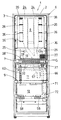
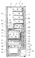
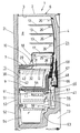
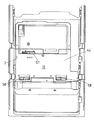
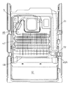
次に、図面に基づき本発明の実施形態を詳述する。図1は本発明を適用した実施例としての冷蔵庫1の各扉を除く正面図、図2は同じく扉を除く冷蔵庫1の一部切欠正面図、図3は冷蔵庫1の縦断側面図、図4は冷蔵庫1のもう一つの縦断側面図である。
【0024】
本発明の冷蔵庫1は、前方に開口する鋼板製の外箱2と、硬質樹脂製の内箱3間に発泡ポリウレタン断熱材4を現場発泡方式により充填して成る断熱箱体6により構成されており、この断熱箱体6の庫内は、略中央部に設けられた区画部材7によって上下に区画され、この区画部材7の上方を冷蔵温度(+5℃程)に維持される冷蔵室8としている。
【0025】
区画部材7の下方は更に断面略L字状の断熱仕切壁9にて上下に区画され、この断熱仕切壁9と区画部材7の間を野菜などの乾燥を嫌う食品を収納するための野菜室11とし、断熱仕切壁9の下方を凍結温度(−20℃程)に冷却される冷凍室12としている。
【0026】
前記冷蔵室8内には上下複数段の棚13・・が架設されており、その下部には上面に開口する氷温容器16が前後方向に納出自在に配置されている。この氷温容器16の上側は棚板17にて閉塞され、前面は氷温容器16の引き出し動作で開閉する蓋18にて閉じられており、これによって、氷温容器16内に氷温(0℃〜−3℃)に維持される氷温室19を構成する。また、冷蔵室8の前面開口は回動式の扉21にて開閉自在に閉塞されている。
【0027】
更に、冷蔵室8の背部には上部がY字状に分岐した冷蔵室ダクト24が上下に渡って形成されており、その左右には冷蔵室ダクト24の上端部と冷蔵室8内に連通した冷蔵室冷気吐出口26が上下に複数形成されている。また、前記氷温容器16内の氷温室19の背方にも冷蔵室ダクト24に連通した氷温室冷気吐出口25、25が形成されると共に、その奥部には冷蔵室冷気戻り口27が形成されている。即ち、氷温室19内を循環した冷気と冷蔵室8内を循環した冷気の一部はこの冷蔵室冷気戻り口27に流入する。
【0028】
一方、前記区画部材7は、後部の仕切板28とその前側の仕切前断熱部材29とから構成されている。仕切板28の前部には、冷蔵室冷気戻り口31が形成されており、氷温容器16の前部下側に位置している。この氷温容器16は仕切板28と仕切前断熱部材29上に間隔を存して架設されており、これによって、扉21の内側を降下して来た冷蔵室8内の冷気は、氷温容器16の前側から冷蔵室冷気戻り口31に流入可能としている。
【0029】
他方、仕切前断熱部材29の下面は後端部から前方に低く傾斜している。また、この仕切前断熱部材29の下面前部には上蓋32が前方から差し込まれて固定されている。この上蓋32は仕切前断熱部材29及び仕切板28の下側に位置し、その固定部分を除いて仕切前断熱部材29及び仕切板28との間に所定の間隔Gを形成する。そして、この間隔Gは少なくとも上蓋32の前端部で野菜室11内に開放している。
【0030】
この間隔Gの後端は連通孔33にてその後方のダクト空間34に連通しており、ダクト空間34の上部は前記冷蔵室冷気戻り口27に連通している。また、前記冷蔵室ダクト24からはバイパスダクト36が分岐して形成されており、このバイパスダクト36はダクト空間34の上部に連通している。
【0031】
そして、前記野菜室11の右上奥部には野菜室冷気戻り口37が形成されており、この野菜室11の前面開口は引き出し式の扉38により開閉自在に閉塞される。この場合、扉38の後面左右には図示しない扉側レールが後方に延在して取り付けられており、内箱3側左右には内箱側レール42が取り付けられ、扉側レールがローラを介して内箱側レール42に滑動自在に支持されるものである。
【0032】
そして、この扉側レールには扉38の裏面に位置して上面に開口した野菜容器43が取り付けられる。この野菜容器43の上縁周囲は、扉38が閉じられた状態で上蓋32に密着し、それによって、上面開口は閉塞される。
【0033】
一方、前記冷凍室12の背部には仕切板44により冷却室46が画成されており、この冷却室46は冷凍室12の背方から野菜室11後面の断熱仕切壁9の背方まで渡っている。そして、この冷却室36内には冷却装置を構成する冷却器47が縦設されると共に、この冷却器47の上方の冷却室46内には、野菜室11背方の断熱仕切壁9背方に位置して送風機48が設置されている。尚、図5は仕切板44を装着した状態の冷凍室12の正面図である。図6は仕切板44を取り去った冷却室46の正面図で、図6中49は冷却器47の除霜ヒータである。
【0034】
この冷凍室12の前面開口は前述の扉38の場合と同様の方式で引き出し自在とされた上下二段の引き出し式の扉51、52により開閉自在に閉塞される。これら扉51、52の裏面にはそれぞれ上面に開口した容器53、54が取り付けられると共に、各容器53、54が冷凍室12内の上下に配置されて、冷凍食品やアイスクリームなどを収納するかたちとなる。
【0035】
前記仕切板44と冷却器47及び送風機48間には冷気分配用ダクト56が形成されており、仕切板44にはこのダクト56と冷凍室12とに連通する冷凍室冷気吐出口57、58が各容器53、54の上奥部に対応して開口している。また、断熱仕切壁9の下面にはダクト56に連通した冷凍室用冷気ダクト64が形成されている。冷凍室12内上部には自動製氷機61が取り付けられており、自動製氷機61には冷凍室冷気吐出口57から冷気が供給される。尚、62はこの自動製氷機61への給水管である。また、容器54の背方には冷却室46の下部に連通した冷凍室冷気戻り口63が形成されている。
【0036】
ダクト56の上部には送風機48の側方に位置して冷気分配口66が形成され、この冷気分配口66から上昇する連通ダクト67は、野菜室11の背方において冷蔵室ダクト24の下端に連通している。この連通ダクト67内には、前記各吐出口26、25やバイパスダクト36の手前に位置して、モータ駆動のダンパー68が取り付けられており、野菜室11の背方に位置している。
【0037】
また、冷却器47の右側方には冷蔵室・野菜室冷気戻りダクト71が形成されており、
その上端は前記野菜室冷気戻り口37に連通し、その下端は冷却室46の下部に開口した冷蔵室・野菜室冷気戻り口72にて冷却室46内に連通している。
【0038】
この場合、冷却器47下側の冷却室46には右方に突出した凹部46A(図6参照)が連続して形成されており、前記冷蔵室・野菜室冷気戻り口72は、この凹部46Aの上面において、下前方に指向した状態で開放している(図3参照)。
【0039】
一方、断熱箱体6の底壁は後部が階段状に立ち上がる形状とされており、この底壁の後部外側には機械室73が形成されている。この機械室73内には冷却装置を構成する図示しない圧縮機や蒸発皿コンデンサなどが設置される。
【0040】
係る構成で動作及び冷気循環を説明する。前記圧縮機と送風機48が運転されると、冷却器47が冷却作用を発揮する。この冷却器47にて冷却された極めて低温(−25℃〜−30℃)の冷気は上方の送風機48の運転により吸引され、前方の分配ダクト56に吹き出される。分配ダクト56に吹き出された冷気は冷凍室冷気吐出口57、58及び冷凍室用ダクト64から冷凍室12内の各容器53、54及び自動製氷機61内に吐出され、−20℃程の凍結温度に冷却すると共に、製氷を行う。そして、冷凍室12内の冷気は冷凍室冷気戻り口63から冷却器47の吸い込み側の冷却室46内に帰還する(各図に矢印で示す)。
【0041】
分配ダクト56に吹き出された冷気はまた、冷気分配口66から連通ダクト67及びダンパー68を経て冷蔵室ダクト24に流入し、そこを上昇した後、各冷蔵室冷気吐出口26・・及び氷温室冷気吐出口25より冷蔵室8及び氷温室19内に吐出される(図中矢印参照)。ダンパー68は冷蔵室8内の温度に基づき制御されて連通ダクト67を開閉し、それによって、冷蔵室8内を+5℃程の冷蔵温度に、氷温室19内は0℃〜−3℃程の氷温に維持される。
【0042】
尚、このダンパー68を経た冷気(冷却器47と熱交換した直後の低温の冷気)の一部は前記バイパスダクト36に流入し、直接ダクト空間34の上部に流入する。
【0043】
他方、冷蔵室8内を循環して扉21の内側を流下して来た冷気は、氷温容器16の前部下側の冷蔵室冷気戻り口31から上蓋32と区画部材7間の間隔G内に流入する。そして、前方に移動しながら仕切前断熱部材29下面の傾斜に沿って下方の野菜容器43周囲の野菜室11内の空間に流下する。
【0044】
また、氷温室19内を循環した冷気と、冷蔵室8内を循環した冷気の残りは後部の冷蔵室冷気戻り口27からダクト空間34内上部に流入し、そこで、バイパスダクト36を経て来た低温の冷気と混合される。その後、連通孔33から間隔Gの後部に流入し、前述同様に前方に移動し、途中冷蔵室冷気戻り口31からの冷気と混じり合いながら仕切前断熱部材29下面の傾斜に沿って下方の野菜容器43周囲の野菜室11内の空間に流下する。
【0045】
これによって、野菜容器43内を周囲から保冷する。そして、野菜室11内を循環した冷気は野菜室冷気戻り口37より冷蔵室・野菜室冷気戻りダクト71に流入し、そこを流下して冷蔵室・野菜室冷気戻り口72より冷却器47の吸い込み側の冷却室46内に帰還する(各図中矢印参照)。
【0046】
このとき、冷蔵室・野菜室冷気戻り口72は、冷却器47下側の冷却室46に連続して右方に突出形成された凹部46Aの上面において、下前方に指向した状態で開放されているので、冷却器56との間に充分な距離が確保されている。従って、比較的温度の高い湿った冷気が冷蔵室・野菜室冷気戻り口72から冷却室46内に吹き出されても、戻り口7
2周囲に着霜が生じ難くなる。
【0047】
また、冷却器56の局部的な着霜も生じ難くなるので、霜閉塞による冷却効果の悪化も抑制される。そして、除霜ヒータ49による冷却器47の除霜時にも露水が戻り口72に付着することが無くなると共に、戻り口72は冷却室46(凹部46Aを含む)底面から離間しているので、除霜時に冷却器47から滴下した除霜水が戻り口72に流入する危険性も無い。これにより、冷蔵室・野菜室冷気戻り口72周囲の水シールが不要となり、構造が簡素化される。
【0048】
特に、以上のようにダンパー68を経た冷気の一部を、冷蔵室8や氷温室19内を経ること無く直接野菜室11に供給するバイパスダクト36を設けたので、このバイパスダクト36から野菜室11に冷蔵室8などを経ていない新鮮な(低温)冷気を供給することができるようになる。
【0049】
これにより、野菜室11には冷蔵室8からの戻り冷気に加えて低温の冷気が供給されるようになるので、冷蔵室8側の負荷の状況に拘わらず、野菜室11を安定的に冷却することができるようになる。
【0050】
また、区画部材7を、仕切板28とこの仕切板28の前側に設けられた仕切前断熱部材29とから構成し、仕切板28には氷温容器16の前部下側に位置して冷蔵室冷気戻り口31を形成すると共に、仕切前断熱部材29の下面を前方に低く傾斜させたので、冷蔵室8からの戻り冷気は氷温容器16の前部下側から区画部材7と上蓋32間の間隔Gに流入し、前方に移動しながら仕切前断熱部材29下面の傾斜に沿って下方の野菜容器43周囲に流下するようになる。
【0051】
そして、野菜容器43周囲を循環した冷気は野菜室11の上奥部の野菜室冷気戻り口37に流入するので、これらによって、野菜容器43周囲を冷気が満遍なく円滑に循環できるようになり、野菜容器43内を斑無く良好に冷却することが可能となる。特に、冷蔵室冷気戻り口31は氷温容器16の下側にあるので、見え難く、扉21を開けた状態の外観にも支障を生じない。
【0052】
更に、氷温容器16後側に形成されたもう一つの冷蔵室冷気戻り口27から出た冷気がバイパスダクト36を経た冷気と混じり合い、区画部材7と上蓋32間の間隔G後部に流入するようにしたので、バイパスダクト36からの冷気が直接当たる区画部材7の仕切板28或いは上蓋32部分の野菜室11が過冷却されることを防止することができる。これにより、野菜室11の冷却効果を維持しつつ、仕切板28や上蓋32に断熱材を貼る必要性や、野菜室11内の温度斑の発生を一層効果的に解消することができるようになる。
【0053】
【発明の効果】
以上詳述した如く本発明によれば、断熱箱体内に上から冷蔵室、野菜室及び冷凍室を順次画成した冷蔵庫において、冷凍室の背方に画成した冷却室内の冷却器と熱交換した冷気を、送風機により各室内に循環するに当たり、送風機から吐出された冷気を冷凍室及び冷蔵室に分配するダクトと、冷蔵室に向かう冷気量を調整するダンパーとを設け、冷蔵室内を循環した後の冷気を野菜室に供給すると共に、ダンパーを経た冷気の一部を、冷蔵室内を経ること無く直接野菜室に供給するためのバイパスダクトを設けたので、このバイパスダクトから野菜室に冷蔵室を経ていない新鮮な冷気を供給することができるようになる。
【0054】
これにより、野菜室には冷蔵室からの戻り冷気に加えて低温の冷気が供給されるようになるので、冷蔵室側の負荷の状況に拘わらず、野菜室を安定的に冷却することができるようになるものである。
【0055】
また、バイパスダクトを経た冷気を、冷蔵室からの帰還冷気と混合した後、野菜室に供給するようにしたので、バイパスダクトから供給される冷気が直接当たる部分の野菜室内が過冷却されることを防止することができる。これにより、野菜室の冷却効果を維持しつつ、当該部分への断熱材の必要性や、野菜室内の温度斑の発生を効果的に解消することができるようになるものである。
【0056】
特に、バイパスダクトを経た冷気を、冷蔵室と野菜室とを区画する区画部材と野菜容器の上面開口を閉塞する上蓋との間の間隔内で冷蔵室からの帰還冷気と混合させるようにしているので、混合のために格別な合流室を構成する必要が無く冷蔵庫内容積の有効利用を図ることができるようになる。
【0057】
請求項2の発明によれば、上記に加えて送風機とダンパーを冷却器の上方であって、野菜室の背方に設けたので、野菜室背方の無効空間を有効に利用して送風機とダンパーを配設することができる。これにより、冷蔵室の容量増大を図ることができるようになるものである。
【0058】
【0059】
【0060】
【図面の簡単な説明】
【図1】 本発明を適用した実施例としての冷蔵庫の各扉を除く正面図である。
【図2】 同じく扉を除く本発明の冷蔵庫の一部切欠正面図である。
【図3】 本発明の冷蔵庫の縦断側面図である。
【図4】 本発明の冷蔵庫のもう一つの縦断側面図である。
【図5】 本発明の冷蔵庫の冷凍室部分の正面図である。
【図6】 本発明の冷蔵庫の冷却室部分の正面図である。
【符号の説明】
1 冷蔵庫
2 外箱
3 内箱
4 ポリウレタン断熱材
7 区画部材
8 冷蔵室
9 断熱仕切壁
11 野菜室
12 冷凍室
16 氷温容器
24 冷蔵室ダクト
27、31 冷蔵室冷気戻り口
28 仕切板
29 仕切前断熱部材
32 上蓋
34 ダクト空間
36 バイパスダクト
37 野菜室冷気戻り口
43 野菜容器
46 冷却室
47 冷却器
48 送風機
56 分配ダクト
67 連通ダクト
68 ダンパー
G 間隔[0001]
BACKGROUND OF THE INVENTION
The present invention relates to a refrigerator in which a refrigerator compartment is formed in the upper part of a heat insulation box, a freezer compartment is provided in the lower part, and a vegetable compartment is defined between the two compartments.
[0002]
[Prior art]
Conventionally, this type of household refrigerator is composed of a heat insulating box body in which a foam heat insulating material such as polyurethane foam is filled in an on-site foaming method between a steel plate outer box and a hard resin inner box. Vegetables for preserving foods that do not like drying, such as freezer rooms that are cooled to a freezing temperature such as −20 ° C., refrigerator rooms that are maintained at a refrigerating temperature such as + 5 ° C. by partitioning the body A chamber is formed.
[0003]
In particular, in recent years, as shown in, for example, Japanese Patent Application Laid-Open No. 8-338868 (F25D23 / 00), a refrigerator room or a vegetable room in which food is frequently delivered is arranged above, and a freezer room for long-term storage. A refrigerator placed at the bottom of the cabinet has been developed. In this case, the refrigerator compartment is formed in the upper part of the heat insulation box, and the vegetable compartment is formed between the lower freezer compartment and the upper refrigerator compartment.
[0004]
As shown in the above publication, the cool air from the cooler provided on the back of the freezer compartment is circulated and supplied to each chamber by a blower. In this case, conventionally, the cool air from the blower is first ducted. In this way, the flow is divided into a direction toward the freezing room and a direction toward the freezing room, and is supplied to the freezing room as it is and also supplied to the refrigerating room via a damper device.
[0005]
In particular, in the above publication, the damper device is composed of two dampers, and the cold air passing through each damper is supplied to the refrigerator compartment and the chilled compartment formed in the refrigerator compartment. Then, a part of the cold air that passed through the chilled room and the cold air that passed through the refrigerator room were returned to the vegetable room, circulated around the vegetable container in the vegetable room, and then returned to the cooler.
[0006]
Each damper opens and closes a cool air passage to each chamber based on the temperatures of the refrigerator compartment and the chilled chamber.
[0007]
[Problems to be solved by the invention]
Thus, conventionally, the cold air that passed through the refrigeration room or the cold air that passed through the chilled room (part) was circulated to the vegetable room, so if the load on the refrigeration room side is large, or the door of the refrigeration room is opened, etc. When the temperature of the return cold air from the refrigerator compartment becomes high, there is a problem that the cooling capacity of the vegetable compartment decreases and the temperature in the vegetable container rises.
[0008]
Further, conventionally, since a relatively large damper device having two dampers is provided above the blower, the damper device extends to the refrigerating room, which increases the ineffective space in the warehouse.
[0009]
Furthermore, since the supply of cold air to the vegetable compartment is merely caused to flow down from the partition plates of the refrigerator compartment and the vegetable compartment, there has been a problem that the vegetable containers in the vegetable compartment cannot be cooled uniformly.
[0010]
The present invention was made to solve the conventional technical problems, and in a refrigerator in which a refrigerator compartment, a vegetable compartment, and a freezer compartment are sequentially defined from above in a heat insulation box, It is an object of the present invention to allow cold air to be supplied accurately and smoothly and to reduce the ineffective space in the cabinet.
[0011]
[Means for Solving the Problems]
The refrigerator according to the present invention has a refrigerator compartment in the upper part of the heat insulation box, a freezer compartment in the lower part, a vegetable compartment between the two compartments, and cold air exchanged with a cooler in the cooling compartment defined on the back of the freezer compartment Are circulated in each room by a blower, the duct for distributing the cold air discharged from the blower to the freezer room and the refrigerator room, a damper for adjusting the amount of cold air directed to the refrigerator room, the refrigerator room and the vegetables A compartment member for partitioning the chamber, a vegetable container provided in the vegetable compartment so that it can be pulled out, and an upper lid that is attached to the lower side of the compartment member at an interval and closes the top opening of the vegetable container, and is refrigerated Along with supplying the cold air after circulating through the room to the vegetable room, a bypass duct is provided to supply a part of the cold air that has passed through the damper to the vegetable room directly without going through the refrigerator compartment. Between the partition member and the top lid After mixing the feedback cold air from the refrigerating chamber septum, and supplies to the vegetable compartment.
[0012]
According to the present invention, in the refrigerator in which the refrigerator compartment, the vegetable compartment, and the freezer compartment are sequentially defined from above in the heat insulation box, the cool air exchanged with the cooler in the cooling compartment defined on the back of the freezer compartment is sent to the blower. In order to circulate in each room, a duct that distributes the cold air discharged from the blower to the freezer room and the refrigerator room and a damper that adjusts the amount of cold air directed to the refrigerator room are provided, and the cold air after circulating in the refrigerator room is vegetable A bypass duct is provided to supply the vegetable room directly to the vegetable room without passing through the refrigerator, and a portion of the cold air that has passed through the damper is fresh from the bypass duct to the vegetable room. Cold air can be supplied.
[0013]
As a result, low temperature cold air is supplied to the vegetable room in addition to the return cold air from the cold room, so that the vegetable room can be stably cooled regardless of the load on the cold room side. It will be like that.
[0014]
In addition, since the cold air passing through the bypass duct is mixed with the return cold air from the refrigerator compartment and then supplied to the vegetable compartment, the vegetable compartment in the portion directly hit by the cold air supplied from the bypass duct is supercooled. Can be prevented. This makes it possible to effectively eliminate the necessity of a heat insulating material for the portion and the occurrence of temperature spots in the vegetable room while maintaining the cooling effect of the vegetable room.
[0015]
In particular, the cold air that has passed through the bypass duct is mixed with the return cold air from the refrigerator compartment within an interval between the partition member that partitions the refrigerator compartment and the vegetable compartment and the upper lid that closes the top opening of the vegetable container. Therefore, it is not necessary to configure a special merging chamber for mixing, and the refrigerator internal volume can be effectively used.
[0016]
In the refrigerator according to the second aspect of the present invention, the blower and the damper are provided above the cooler and behind the vegetable compartment.
[0017]
According to the invention of
[0018]
[0019]
[0020]
[0021]
[0022]
[0023]
DETAILED DESCRIPTION OF THE INVENTION
Next, embodiments of the present invention will be described in detail with reference to the drawings. FIG. 1 is a front view excluding each door of a
[0024]
The
[0025]
Below the
[0026]
A plurality of upper and
[0027]
Further, a
[0028]
On the other hand, the
[0029]
On the other hand, the lower surface of the pre-partition
[0030]
The rear end of the gap G communicates with the
[0031]
A vegetable room cold
[0032]
And the
[0033]
On the other hand, a cooling
[0034]
The front opening of the
[0035]
A cool
[0036]
In the upper part of the
[0037]
Further, on the right side of the cooler 47, a cold room / vegetable room cold
The upper end communicates with the vegetable room cold
[0038]
In this case, a
[0039]
On the other hand, the bottom wall of the
[0040]
The operation and the cold air circulation will be described with such a configuration. When the compressor and the
[0041]
The cold air blown to the
[0042]
A part of the cold air passing through the damper 68 (low-temperature cold air immediately after heat exchange with the cooler 47) flows into the
[0043]
On the other hand, the cold air that circulates in the refrigerating
[0044]
Further, the cold air circulated in the
[0045]
Thereby, the inside of the
[0046]
At this time, the cold room / vegetable room cold
2 Frost is unlikely to occur around.
[0047]
Moreover, since local frost formation of the cooler 56 is difficult to occur, deterioration of the cooling effect due to frost blockage is also suppressed. Even when defrosting of the cooler 47 by the
[0048]
In particular, as described above, the
[0049]
As a result, low temperature cold air is supplied to the
[0050]
In addition, the
[0051]
And since the cold air which circulated around the
[0052]
Furthermore, the cold air from another cold room
[0053]
【The invention's effect】
As described above in detail, according to the present invention, in the refrigerator in which the refrigerator compartment, the vegetable compartment, and the freezer compartment are sequentially defined in the heat insulation box, heat exchange with the cooler in the cooling compartment defined on the back of the freezer compartment is performed. When circulating the chilled air into each room by a blower, a duct that distributes the chilled air discharged from the blower to the freezer room and the refrigerated room, and a damper that adjusts the amount of cold air that goes to the refrigerated room are provided and circulated in the refrigerated room. A bypass duct is provided to supply the later cold air to the vegetable room and to supply a part of the cold air that has passed through the damper directly to the vegetable room without going through the refrigerator room. It becomes possible to supply fresh cold air that has not passed through.
[0054]
As a result, low temperature cold air is supplied to the vegetable room in addition to the return cold air from the cold room, so that the vegetable room can be stably cooled regardless of the load on the cold room side. It will be like that.
[0055]
In addition, since the cold air passing through the bypass duct is mixed with the return cold air from the refrigerator compartment and then supplied to the vegetable compartment, the vegetable compartment in the portion directly hit by the cold air supplied from the bypass duct is supercooled. Can be prevented. This makes it possible to effectively eliminate the necessity of a heat insulating material for the portion and the occurrence of temperature spots in the vegetable room while maintaining the cooling effect of the vegetable room.
[0056]
In particular, the cold air that has passed through the bypass duct is mixed with the return cold air from the refrigerator compartment within an interval between the partition member that partitions the refrigerator compartment and the vegetable compartment and the upper lid that closes the top opening of the vegetable container. Therefore, it is not necessary to configure a special merging chamber for mixing, and the refrigerator internal volume can be effectively used.
[0057]
According to the invention of
[0058]
[0059]
[0060]
[Brief description of the drawings]
FIG. 1 is a front view excluding doors of a refrigerator as an embodiment to which the present invention is applied.
FIG. 2 is a partially cutaway front view of the refrigerator of the present invention except for the door.
FIG. 3 is a vertical side view of the refrigerator of the present invention.
FIG. 4 is another longitudinal side view of the refrigerator of the present invention.
FIG. 5 is a front view of a freezer compartment portion of the refrigerator of the present invention.
FIG. 6 is a front view of a cooling chamber portion of the refrigerator of the present invention.
[Explanation of symbols]
DESCRIPTION OF
Claims (2)
前記送風機から吐出された冷気を前記冷凍室及び冷蔵室に分配するダクトと、前記冷蔵室に向かう冷気量を調整するダンパーと、前記冷蔵室と野菜室とを区画する区画部材と、前記野菜室内に引き出し自在に設けられた野菜容器と、前記区画部材の下側に間隔を存して取り付けられ、前記野菜容器の上面開口を閉塞する上蓋とを備え、前記冷蔵室内を循環した後の冷気を前記野菜室に供給すると共に、前記ダンパーを経た冷気の一部を、前記冷蔵室内を経ること無く直接前記野菜室に供給するためのバイパスダクトを設け、このバイパスダクトを経た冷気を、前記区画部材と上蓋との間の間隔内で前記冷蔵室からの帰還冷気と混合した後、前記野菜室に供給することを特徴とする冷蔵庫。A refrigerator compartment is formed in the upper part of the heat insulation box, a freezer compartment in the lower part, a vegetable compartment is defined between the two compartments, and the cold air that is heat-exchanged with the cooler in the cooling compartment defined on the back of the freezer compartment is blown by a blower. In the refrigerator that circulates in each room,
A duct that distributes the cold air discharged from the blower to the freezer compartment and the refrigerator compartment, a damper that adjusts the amount of cold air directed to the refrigerator compartment, a partition member that partitions the refrigerator compartment and the vegetable compartment, and the vegetable compartment A vegetable container provided in a freely retractable manner, and an upper lid that is attached to the lower side of the partition member with an interval and closes the upper surface opening of the vegetable container, and cools the air after circulating in the refrigerator compartment A bypass duct is provided for supplying a part of the cold air that has passed through the damper to the vegetable compartment directly to the vegetable compartment without passing through the refrigerator compartment, and the cold air that has passed through the bypass duct is supplied to the vegetable compartment. The refrigerator is supplied to the vegetable compartment after being mixed with the return cold air from the refrigerating compartment within the interval between the top and the lid.
Priority Applications (1)
| Application Number | Priority Date | Filing Date | Title |
|---|---|---|---|
| JP8455397A JP3649850B2 (en) | 1997-03-17 | 1997-03-17 | refrigerator |
Applications Claiming Priority (1)
| Application Number | Priority Date | Filing Date | Title |
|---|---|---|---|
| JP8455397A JP3649850B2 (en) | 1997-03-17 | 1997-03-17 | refrigerator |
Related Child Applications (1)
| Application Number | Title | Priority Date | Filing Date |
|---|---|---|---|
| JP2004194281A Division JP2004271178A (en) | 2004-06-30 | 2004-06-30 | Refrigerator |
Publications (2)
| Publication Number | Publication Date |
|---|---|
| JPH10253218A JPH10253218A (en) | 1998-09-25 |
| JP3649850B2 true JP3649850B2 (en) | 2005-05-18 |
Family
ID=13833846
Family Applications (1)
| Application Number | Title | Priority Date | Filing Date |
|---|---|---|---|
| JP8455397A Expired - Fee Related JP3649850B2 (en) | 1997-03-17 | 1997-03-17 | refrigerator |
Country Status (1)
| Country | Link |
|---|---|
| JP (1) | JP3649850B2 (en) |
Cited By (1)
| Publication number | Priority date | Publication date | Assignee | Title |
|---|---|---|---|---|
| JP2014098548A (en) * | 2014-02-26 | 2014-05-29 | Sharp Corp | Refrigerator |
Families Citing this family (1)
| Publication number | Priority date | Publication date | Assignee | Title |
|---|---|---|---|---|
| WO2011105647A1 (en) | 2010-02-26 | 2011-09-01 | 엘지전자 주식회사 | Refrigerator |
-
1997
- 1997-03-17 JP JP8455397A patent/JP3649850B2/en not_active Expired - Fee Related
Cited By (1)
| Publication number | Priority date | Publication date | Assignee | Title |
|---|---|---|---|---|
| JP2014098548A (en) * | 2014-02-26 | 2014-05-29 | Sharp Corp | Refrigerator |
Also Published As
| Publication number | Publication date |
|---|---|
| JPH10253218A (en) | 1998-09-25 |
Similar Documents
| Publication | Publication Date | Title |
|---|---|---|
| US7036334B2 (en) | Refrigerator having temperature controlled chamber | |
| US8429926B2 (en) | Ice storage bin and icemaker apparatus for refrigerator | |
| US7059142B2 (en) | Refrigerator having temperature controlled chamber | |
| KR20110081704A (en) | Refrigeration and freezing system of refrigerators | |
| JP3573909B2 (en) | refrigerator | |
| JPH10259986A (en) | Refrigerator | |
| JP3857964B2 (en) | Cold air passage control device | |
| JP3649850B2 (en) | refrigerator | |
| JP3599946B2 (en) | refrigerator | |
| US3172714A (en) | Refrigerating apparatus | |
| KR19990030104A (en) | Refrigerator | |
| JP2002013864A (en) | refrigerator | |
| JP2007187362A (en) | refrigerator | |
| JPH10339569A (en) | Shelf device of refrigerator | |
| JP3490861B2 (en) | refrigerator | |
| JP2005221227A (en) | Refrigerator | |
| JP2004271178A (en) | Refrigerator | |
| JPH10259985A (en) | Refrigarator | |
| JP3540549B2 (en) | refrigerator | |
| CN215638298U (en) | Refrigeration appliance | |
| JP2002156176A (en) | Refrigerator | |
| JPH10253235A (en) | Refrigerator | |
| KR20100028828A (en) | A refrigerator | |
| JP2004061085A (en) | Refrigerator | |
| JP3573917B2 (en) | Refrigerator shelf equipment |
Legal Events
| Date | Code | Title | Description |
|---|---|---|---|
| A977 | Report on retrieval |
Effective date: 20040325 Free format text: JAPANESE INTERMEDIATE CODE: A971007 |
|
| A131 | Notification of reasons for refusal |
Free format text: JAPANESE INTERMEDIATE CODE: A131 Effective date: 20040506 |
|
| A521 | Written amendment |
Free format text: JAPANESE INTERMEDIATE CODE: A523 Effective date: 20040701 |
|
| A02 | Decision of refusal |
Free format text: JAPANESE INTERMEDIATE CODE: A02 Effective date: 20040823 |
|
| A521 | Written amendment |
Free format text: JAPANESE INTERMEDIATE CODE: A523 Effective date: 20041021 |
|
| A911 | Transfer of reconsideration by examiner before appeal (zenchi) |
Free format text: JAPANESE INTERMEDIATE CODE: A911 Effective date: 20050107 |
|
| TRDD | Decision of grant or rejection written | ||
| A01 | Written decision to grant a patent or to grant a registration (utility model) |
Effective date: 20050201 Free format text: JAPANESE INTERMEDIATE CODE: A01 |
|
| A61 | First payment of annual fees (during grant procedure) |
Effective date: 20050216 Free format text: JAPANESE INTERMEDIATE CODE: A61 |
|
| FPAY | Renewal fee payment (prs date is renewal date of database) |
Free format text: PAYMENT UNTIL: 20090225 Year of fee payment: 4 |
|
| LAPS | Cancellation because of no payment of annual fees |