JP3649848B2 - Magnetoresistive head and magnetic disk drive having the same - Google Patents
Magnetoresistive head and magnetic disk drive having the same Download PDFInfo
- Publication number
- JP3649848B2 JP3649848B2 JP06691497A JP6691497A JP3649848B2 JP 3649848 B2 JP3649848 B2 JP 3649848B2 JP 06691497 A JP06691497 A JP 06691497A JP 6691497 A JP6691497 A JP 6691497A JP 3649848 B2 JP3649848 B2 JP 3649848B2
- Authority
- JP
- Japan
- Prior art keywords
- slider
- magnetoresistive
- magnetic disk
- magnetoresistive head
- film
- Prior art date
- Legal status (The legal status is an assumption and is not a legal conclusion. Google has not performed a legal analysis and makes no representation as to the accuracy of the status listed.)
- Expired - Fee Related
Links
Images


Classifications
-
- G—PHYSICS
- G11—INFORMATION STORAGE
- G11B—INFORMATION STORAGE BASED ON RELATIVE MOVEMENT BETWEEN RECORD CARRIER AND TRANSDUCER
- G11B5/00—Recording by magnetisation or demagnetisation of a record carrier; Reproducing by magnetic means; Record carriers therefor
- G11B5/127—Structure or manufacture of heads, e.g. inductive
- G11B5/33—Structure or manufacture of flux-sensitive heads, i.e. for reproduction only; Combination of such heads with means for recording or erasing only
- G11B5/39—Structure or manufacture of flux-sensitive heads, i.e. for reproduction only; Combination of such heads with means for recording or erasing only using magneto-resistive devices or effects
- G11B5/3903—Structure or manufacture of flux-sensitive heads, i.e. for reproduction only; Combination of such heads with means for recording or erasing only using magneto-resistive devices or effects using magnetic thin film layers or their effects, the films being part of integrated structures
-
- G—PHYSICS
- G11—INFORMATION STORAGE
- G11B—INFORMATION STORAGE BASED ON RELATIVE MOVEMENT BETWEEN RECORD CARRIER AND TRANSDUCER
- G11B5/00—Recording by magnetisation or demagnetisation of a record carrier; Reproducing by magnetic means; Record carriers therefor
- G11B5/127—Structure or manufacture of heads, e.g. inductive
- G11B5/33—Structure or manufacture of flux-sensitive heads, i.e. for reproduction only; Combination of such heads with means for recording or erasing only
- G11B5/39—Structure or manufacture of flux-sensitive heads, i.e. for reproduction only; Combination of such heads with means for recording or erasing only using magneto-resistive devices or effects
- G11B5/3903—Structure or manufacture of flux-sensitive heads, i.e. for reproduction only; Combination of such heads with means for recording or erasing only using magneto-resistive devices or effects using magnetic thin film layers or their effects, the films being part of integrated structures
- G11B5/3967—Composite structural arrangements of transducers, e.g. inductive write and magnetoresistive read
-
- G—PHYSICS
- G11—INFORMATION STORAGE
- G11B—INFORMATION STORAGE BASED ON RELATIVE MOVEMENT BETWEEN RECORD CARRIER AND TRANSDUCER
- G11B5/00—Recording by magnetisation or demagnetisation of a record carrier; Reproducing by magnetic means; Record carriers therefor
- G11B5/40—Protective measures on heads, e.g. against excessive temperature
-
- G—PHYSICS
- G11—INFORMATION STORAGE
- G11B—INFORMATION STORAGE BASED ON RELATIVE MOVEMENT BETWEEN RECORD CARRIER AND TRANSDUCER
- G11B5/00—Recording by magnetisation or demagnetisation of a record carrier; Reproducing by magnetic means; Record carriers therefor
- G11B5/48—Disposition or mounting of heads or head supports relative to record carriers ; arrangements of heads, e.g. for scanning the record carrier to increase the relative speed
- G11B5/488—Disposition of heads
- G11B5/4886—Disposition of heads relative to rotating disc
-
- G—PHYSICS
- G11—INFORMATION STORAGE
- G11B—INFORMATION STORAGE BASED ON RELATIVE MOVEMENT BETWEEN RECORD CARRIER AND TRANSDUCER
- G11B19/00—Driving, starting, stopping record carriers not specifically of filamentary or web form, or of supports therefor; Control thereof; Control of operating function ; Driving both disc and head
- G11B19/02—Control of operating function, e.g. switching from recording to reproducing
- G11B19/04—Arrangements for preventing, inhibiting, or warning against double recording on the same blank or against other recording or reproducing malfunctions
-
- G—PHYSICS
- G11—INFORMATION STORAGE
- G11B—INFORMATION STORAGE BASED ON RELATIVE MOVEMENT BETWEEN RECORD CARRIER AND TRANSDUCER
- G11B5/00—Recording by magnetisation or demagnetisation of a record carrier; Reproducing by magnetic means; Record carriers therefor
- G11B5/012—Recording on, or reproducing or erasing from, magnetic disks
-
- G—PHYSICS
- G11—INFORMATION STORAGE
- G11B—INFORMATION STORAGE BASED ON RELATIVE MOVEMENT BETWEEN RECORD CARRIER AND TRANSDUCER
- G11B5/00—Recording by magnetisation or demagnetisation of a record carrier; Reproducing by magnetic means; Record carriers therefor
- G11B5/127—Structure or manufacture of heads, e.g. inductive
- G11B5/31—Structure or manufacture of heads, e.g. inductive using thin films
- G11B5/3109—Details
- G11B5/3116—Shaping of layers, poles or gaps for improving the form of the electrical signal transduced, e.g. for shielding, contour effect, equalizing, side flux fringing, cross talk reduction between heads or between heads and information tracks
-
- G—PHYSICS
- G11—INFORMATION STORAGE
- G11B—INFORMATION STORAGE BASED ON RELATIVE MOVEMENT BETWEEN RECORD CARRIER AND TRANSDUCER
- G11B5/00—Recording by magnetisation or demagnetisation of a record carrier; Reproducing by magnetic means; Record carriers therefor
- G11B5/48—Disposition or mounting of heads or head supports relative to record carriers ; arrangements of heads, e.g. for scanning the record carrier to increase the relative speed
- G11B5/58—Disposition or mounting of heads or head supports relative to record carriers ; arrangements of heads, e.g. for scanning the record carrier to increase the relative speed with provision for moving the head for the purpose of maintaining alignment of the head relative to the record carrier during transducing operation, e.g. to compensate for surface irregularities of the latter or for track following
Landscapes
- Engineering & Computer Science (AREA)
- Manufacturing & Machinery (AREA)
- Adjustment Of The Magnetic Head Position Track Following On Tapes (AREA)
- Magnetic Heads (AREA)
- Supporting Of Heads In Record-Carrier Devices (AREA)
Description
【0001】
【発明の属する技術分野】
本発明は、磁気ディスクに対して情報の記録再生を行う磁気ディスク装置に使用される磁気抵抗効果型ヘッドに関する。
近年、磁気ディスクが小径化されて磁気ディスク装置の小型化が進んでいる。磁気ディスクが小径化すると、磁気ディスクとヘッドとの相対速度が遅くなる。磁気抵抗効果型ヘッドは、磁気抵抗効果の原理でもって磁気ディスク上の信号を読み出すものであり、磁気ディスクと磁気抵抗効果型ヘッドとの相対速度が大きくなくても出力レベルの大きい読みだし信号を得ることができるため、磁気ディスク装置の小型化に好適である。
【0002】
この磁気抵抗効果型ヘッドは、後述するサーマルアスペリティによる信号異常の問題があり、これを解決する必要がある。
また、近年の高密度記録化に伴って磁気抵抗効果型ヘッドの磁気ディスクに対する浮上量が小さくなっている。浮上量が小さくなると、サーマルアスペリティによる信号異常の程度が大きくなり易くなるため、これに対する解決を図ることが重要となる。
【0003】
【従来の技術】
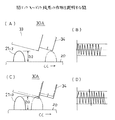
図14(A),(B)は、従来の磁気抵抗効果型ヘッド10を示す。磁気抵抗効果型ヘッド10は、スライダ11と、スライダ11の空気流出端の面11a上の膜構造部12とを有する。膜構造部12は、磁気抵抗効果素子13を有する。膜構造部12の端面12aは、スライダ11の浮上面11bの延長面上に位置している。即ち、端面12aは浮上面11bと同じ面である。
【0004】
磁気ディスク20が矢印CC方向に回転し、磁気抵抗効果型ヘッド10は、空気流21の作用で、浮上量h、浮上角αで(磁気抵抗効果素子13側が下がった姿勢で)磁気ディスク20の上面20aから浮上し続け、信号を読み出す。
【0005】
磁気ヘッドがコンタクトスタートストップするときの磁気ヘッドの磁気ディスクへの吸着を防止する目的で、磁気ディスクは、基板にテクスチャリングを施し、このテクスチャリングを施した面に膜を形成して製造される。磁気ディスクの表面の粗さRaは、10〜50Å程度であり、浮上している磁気抵抗効果型ヘッドに当たらないようになっている。
【0006】
【発明が解決しようとする課題】
テクスチャリングはメカニカル的に形成され又はレーザによって形成されており、磁気ディスクの表面の粗さRaはばらつく。図14(B)に示すように、上面20aから突き出した微小突起21を有する場合がある。
近年の高密度記録化に伴って磁気抵抗効果型ヘッドの磁気ディスクに対する浮上量hは、30〜50nmと小さくなってきており、この微小突起21が、図14(B)に二点鎖線で示すように、膜構造部12の端面12aに衝突し易い。また、サーマルアスペリティによる盛り上がり変形量Nh(図7(B)参照)が約5nmだと、マージンが悪くなり、当たる確率は更に高くなる。
【0007】
微小突起21が膜構造部12の端面12aのうち磁気抵抗効果素子13に衝突することが起きると、磁気抵抗効果素子13が一時的に発熱し、これによって磁気抵抗効果素子13の抵抗値が一時的に変化し、読みだし信号25に、図14(C)に符号26で示すような異常信号が発生する。この異常信号26を、サーマルアスペリティによる信号異常という。
【0008】
従来は、サーマルアスペリティ対策として、磁気ディスクの表面品質を改善すること、或いは、サーマルアスペリティによる信号異常を抑える信号処理回路を設けることが採られている。
磁気抵抗効果型ヘッド10の浮上量hが少なくなると、微小突起21が膜構造部12の端面12aに衝突するエネルギーが増すため、異常信号26の出力レベルLが大きくなる傾向にある。よって、上記の対策では十分でなくなってきつつある。
【0009】
そこで、本発明は上記課題を解決した磁気抵抗効果型ヘッド及びこれを有する磁気ディスク装置を提供することを目的とする。
【0010】
【課題を解決するための手段】
請求項1の発明は、磁気ディスクに対して所定の浮上角傾斜して浮上するスライダと、このスライダの空気流出端に形成してあり、情報の再生を行うため磁気抵抗効果素子を含む膜状素子構造部とを有する磁気抵抗効果型ヘッドにおいて、
該膜状素子構造部の該スライダの浮上面と同じ側の端面が、該スライダの浮上面より所定の段差寸法後退した位置にあり、
該所定の段差寸法が、上記磁気抵抗効果型ヘッドを上記磁気ディスクに対して上記の所定の浮上角傾斜させた姿勢として上記スライダの空気流出端の角部を通り上記磁気ディスクと平行な仮想面を考えた場合に、上記磁気抵抗効果素子の上記端面に臨んでいる端部を上記仮想面より上側に位置させるに足る寸法を有する構成としたものである。
【0012】
請求項2の発明は、磁気ディスクに対して所定の浮上角傾斜して浮上するスライダと、このスライダの空気流出端に形成してあり、情報の再生を行うため磁気抵抗効果素子を含む膜状素子構造部とを有する磁気抵抗効果型ヘッドにおいて、 該膜状素子構造部の該スライダの浮上面と同じ側の端面が、該スライダの浮上面より所定の段差寸法後退した位置にあり、
該所定の段差寸法が、上記磁気抵抗効果型ヘッドを上記磁気ディスクに対して上記の所定の浮上角傾斜させた姿勢として上記スライダの空気流出端の角部を通り上記磁気ディスクと平行な仮想面を考えた場合に、磁気抵抗効果素子の上記端面に臨んでいる端部を上記仮想面より上側に位置させるに足る寸法に、上記膜状素子構造部が熱膨張したときの上記端面の盛り上がり変形量を加算した寸法を有する構成としたものである。
【0013】
請求項3の発明は、磁気ディスクに対して所定の浮上角傾斜して浮上するスライダと、このスライダの空気流出端に形成してあり、情報の再生を行うため磁気抵抗効果素子を含む膜状素子構造部とを有する磁気抵抗効果型ヘッドにおいて、 該膜状素子構造部の該スライダの浮上面と同じ側の端面が、該スライダの浮上面より所定の段差寸法後退した位置にあり、
該所定の段差寸法が、上記磁気抵抗効果型ヘッドを上記磁気ディスクに対して上記の所定の浮上角傾斜させた姿勢として上記スライダの空気流出端の角部を通り上記磁気ディスクと平行な仮想面を考えた場合に、磁気抵抗効果素子の上記端面に臨んでいる端部を上記仮想面より上側に位置させるに足る寸法に、上記スライダが上記磁気ディスク上の微小突起を相対的に乗り越えたときのステップダウン分を加算した寸法を有する構成としたものである。
【0014】
請求項4の発明は、磁気ディスクに対して所定の浮上角傾斜して浮上するスライダと、このスライダの空気流出端に形成してあり、情報の再生を行うため磁気抵抗効果素子を含む膜状素子構造部とを有する磁気抵抗効果型ヘッドにおいて、
該膜状素子構造部の該スライダの浮上面と同じ側の端面が、該スライダの浮上面より所定の段差寸法後退した位置にあり、
該所定の段差寸法が、上記磁気抵抗効果型ヘッドを上記磁気ディスクに対して上記の所定の浮上角傾斜させた姿勢として上記スライダの空気流出端の角部を通り上記磁気ディスクと平行な仮想面を考えた場合に、磁気抵抗効果素子の上記端面に臨んでいる端部を上記仮想面より上側に位置させるに足る寸法に、上記膜状素子構造部が熱膨張したときの上記端面の盛り上がり変形量と上記スライダが上記磁気ディスク上の微小突起を相対的に乗り越えたときのステップダウン分とを加算した寸法を有する構成としたものである。
【0015】
請求項5の発明は、磁気ディスクに対して所定の浮上角傾斜して浮上するスライダと、このスライダの空気流出端に形成してあり、情報の再生を行うため磁気抵抗効果素子を含む膜状素子構造部とを有する磁気抵抗効果型ヘッドにおいて、
該膜状素子構造部の該スライダの浮上面と同じ側の端面が、該スライダの浮上面より所定の段差寸法後退した位置にあり、
該所定の段差寸法が、上記磁気抵抗効果型ヘッドを上記磁気ディスクに対して上記の所定の浮上角傾斜させた姿勢として上記スライダの空気流出端の角部を通り上記磁気ディスクと平行な仮想面を考えた場合に、該膜状素子構造部の上記端面の空気流出端の端部を上記仮想面より上側に位置させるに足る寸法を有する構成としたものである。
【0016】
請求項6の発明は、磁気ディスクに対して傾斜して浮上するスライダと、このスライダの空気流出端に形成してあり、情報の再生を行うため磁気抵抗効果素子を含む膜状素子構造部とを有する磁気抵抗効果型ヘッドにおいて、
該膜状素子構造部の該スライダの浮上面と同じ側の端面の該スライダの浮上面より後退した段差の寸法Y1が、
Y1≧t1×tanα
(ここで、t1は上記スライダの空気流出端の面から上記磁気抵抗効果素子までの距離、αは上記磁気抵抗効果型ヘッドの浮上角である。)
を満たす大きさである構成としたものである。
【0017】
請求項7の発明は、磁気ディスクに対して傾斜して浮上するスライダと、このスライダの空気流出端に形成してあり、情報の再生を行うため磁気抵抗効果素子を含む膜状素子構造部とを有する磁気抵抗効果型ヘッドにおいて、
該膜状素子構造部の該スライダの浮上面と同じ側の端面の該スライダの浮上面より後退した段差の寸法Y2が、
Y2≧t2×tanα
(ここで、t2は上記膜状素子構造部の厚さ、αは上記磁気抵抗効果型ヘッドの浮上角である。)
を満たす大きさである構成としたものである。
【0018】
請求項8の発明は、磁気ディスクに対して傾斜して浮上するスライダと、このスライダの空気流出端に形成してあり、情報の再生を行うため磁気抵抗効果素子を含む膜状素子構造部とを有する磁気抵抗効果型ヘッドにおいて、
該膜状素子構造部の該スライダの浮上面と同じ側の端面の該スライダの浮上面より後退した段差の寸法Y3が、
Y3≧(t1×tanα)+Nh
(ここで、t1は上記スライダの空気流出端の面から上記磁気抵抗効果素子までの距離、αは上記磁気抵抗効果型ヘッドの浮上角、Nhは膜状素子構造部の熱膨張による盛り上がり変形量である。)
を満たす大きさである構成としたものである。
【0019】
請求項9の発明は、磁気ディスクに対して傾斜して浮上するスライダと、このスライダの空気流出端に形成してあり、情報の再生を行うため磁気抵抗効果素子を含む膜状素子構造部とを有する磁気抵抗効果型ヘッドにおいて、
該膜状素子構造部の該スライダの浮上面と同じ側の端面の該スライダの浮上面より後退した段差の寸法Y4が、
Y4≧(t1×tanα)+Z
(ここで、t1は上記スライダの空気流出端の面から上記磁気抵抗効果素子までの距離、αは上記磁気抵抗効果型ヘッドの浮上角、Zは磁気抵抗効果型ヘッドが磁気ディスクの微小突起によって一旦押し上げられた後に下動してステップダウンした距離である。)
を満たす大きさである構成としたものである。
【0020】
請求項10の発明は、磁気ディスクに対して傾斜して浮上するスライダと、このスライダの空気流出端に形成してあり、情報の再生を行うため磁気抵抗効果素子を含む膜状素子構造部とを有する磁気抵抗効果型ヘッドにおいて、
該膜状素子構造部の該スライダの浮上面と同じ側の端面の該スライダの浮上面より後退した段差の寸法Y5が、
Y5≧(t1×tanα)+Nh+Z
(ここで、t1は上記スライダの空気流出端の面から上記磁気抵抗効果素子までの距離、αは上記磁気抵抗効果型ヘッドの浮上角、Nhは膜状素子構造部の熱膨張による盛り上がり変形量、Zは磁気抵抗効果型ヘッドが磁気ディスクの微小突起によって一旦押し上げられた後に下動してステップダウンした距離である。)
を満たす大きさである構成としたものである。
【0021】
請求項11の発明は、磁気ディスクに対して傾斜して浮上するスライダと、このスライダの空気流出端に形成してあり、情報の再生を行うため磁気抵抗効果素子を含む膜状素子構造部とを有する磁気抵抗効果型ヘッドにおいて、
該膜状素子構造部の該スライダの浮上面と同じ側の端面の該スライダの浮上面より後退した段差の寸法Y3’が、
Y3’≧(t2×tanα)+Nh
(ここで、t2は上記膜状素子構造部の厚さ、αは上記磁気抵抗効果型ヘッドの浮上角、Nhは膜状素子構造部の熱膨張による盛り上がり変形量である。)を満たす大きさである構成としたものである。
【0022】
請求項12の発明は、磁気ディスクに対して傾斜して浮上するスライダと、このスライダの空気流出端に形成してあり、情報の再生を行うため磁気抵抗効果素子を含む膜状素子構造部とを有する磁気抵抗効果型ヘッドにおいて、
該膜状素子構造部の該スライダの浮上面と同じ側の端面の該スライダの浮上面より後退した段差の寸法Y4’が、
Y4’≧(t2×tanα)+Z
(ここで、t2は上記膜状素子構造部の厚さ、αは上記磁気抵抗効果型ヘッドの浮上角、Zは磁気抵抗効果型ヘッドが磁気ディスクの微小突起によって一旦押し上げられた後に下動してステップダウンした距離である。)
を満たす大きさである構成としたものである。
【0023】
請求項13の発明は、磁気ディスクに対して傾斜して浮上するスライダと、このスライダの空気流出端に形成してあり、情報の再生を行うため磁気抵抗効果素子を含む膜状素子構造部とを有する磁気抵抗効果型ヘッドにおいて、
該膜状素子構造部の該スライダの浮上面と同じ側の端面の該スライダの浮上面より後退した段差の寸法Y5’が、
Y5’≧(t2×tanα)+Nh+Z
(ここで、t2は上記膜状素子構造部の厚さ、αは上記磁気抵抗効果型ヘッドの浮上角、Nhは膜状素子構造部の熱膨張による盛り上がり変形量、Zは磁気抵抗効果型ヘッドが磁気ディスクの微小突起によって一旦押し上げられた後に下動してステップダウンした距離である。)
を満たす大きさである構成としたものである。
【0024】
請求項14の発明は、回転する磁気ディスクと、
請求項1乃至請求項13のうちいずれか一項記載の磁気抵抗効果型ヘッドと、 該磁気抵抗効果型ヘッドを上記磁気ディスク上を移動するように支持する支持手段とを有する構成としたものである。
請求項15の発明は、請求項14において、該支持手段は、配線パターンが形成されており、磁気抵抗効果型ヘッドが固定してあるサスペンションよりなり、 該磁気抵抗効果型ヘッドの端子部と該配線パターンの端子とが金ボールによって接続されている構成としたものである。
【0025】
【発明の実施の形態】
〔第1実施例〕
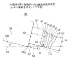
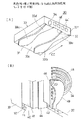
図1及び図2(A)、(B)は、本発明の第1実施例になる磁気抵抗効果型ヘッド30を示す。矢印CC方向は空気流の方向であり、磁気抵抗効果型ヘッド30の構成は、空気流の方向を基準に説明する。
【0026】
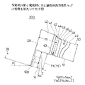
磁気抵抗効果型ヘッド30は、空気流入端31と空気流出端32とを有する。磁気抵抗効果型ヘッド30は、Al2 O3 TiCからなりブロック状にカットされたスライダ33と、スライダ33に半導体術により成膜された膜状素子構造部34とを有する。
スライダ33は、下面(磁気ディスク装置に組み込まれた状態で磁気ディスクに対向する面)に、2つのレール33a,33bを有し、且つ2つのレール33a,33bの間に浅い凹部33cを有する。レール33a,33b及び浅い凹部33cは、共に、CC方向に延在している。33d,33eは浮上面であり、レール33a,33bの下面である。
【0027】
33gはスライダ33の浮上面33dと空気流出端32の面33fとによって形成されている角部(アルチックエッジ)である。
膜状素子構造部34は、スライダ33の空気流出端32の面33fのうちレール33aに対応する部位に形成してある。膜状素子構造部34は、面33fより順に、下地層としてアルミナ等の絶縁膜40、FeN(窒化鉄)等の下部シールド膜(磁性膜)41、アルミナ等の絶縁膜42、膜状の磁気抵抗効果素子43及びこの両端に接続された膜状の導電部材44、アルミナ等の絶縁膜45、シールド膜を兼ねる下部磁性膜46、絶縁膜47、膜状のコイル48、上部磁性膜49、保護膜50が積層された構造を有する。
【0028】
面33fには、導電部材44の端部が磁気抵抗効果素子用の端子部44’として、及び、コイル48の端部がインダクティブヘッド用の端子部48’として露出している。端子部44’、48’は、図3の装置の場合、リード線が半田付けされて、ヘッドを駆動するためのヘッドIC等の回路へ連結されている。
51は、膜状素子構造部34のうち上記浮上面33dと同じ側に位置する端面である。
【0029】
下部磁性膜46、絶縁膜47、膜状のコイル48、上部磁性膜49が、記録専用素子を構成する。磁気抵抗効果素子43が再生専用素子を構成する。
となる。
端面51は、浮上面33dより後退しており、浮上面33dに対して段差寸法Y1の段差52を有している。端面51は、浮上面33dと平行である。
【0030】
ここで、段差52の大きさ、即ち、段差寸法Y1は、磁気抵抗効果型ヘッド30の浮上角をαラジアン、膜状素子構造部34のうちスライダ33の面33fから磁気抵抗効果素子43までの距離(絶縁膜40、下部シールド膜(磁性膜)41、絶縁膜42の厚さを加算した値)をt1とした場合に、浮上角αが相当に小さいため、t1×tanαで表される大きさと同じかこれより大きい。即ち、Y1≧t1×tanαである。
【0031】
磁気抵抗効果型ヘッド30の浮上角αは通常例えば0.20ラジアンであり、距離t1は例えば10μmである。この場合に、段差寸法Y1は、約2μmである。
図1を参照して図学的にみると、段差寸法Y1は、磁気抵抗効果型ヘッド30を浮上角α傾斜している姿勢とし、角部(アルチックエッジ)33gを通り上記磁気ディスクと平行な仮想面55を考えた場合に、磁気抵抗効果素子43の上記端面51に臨んでいる端部を、上記仮想面55より上側に位置させるに足る寸法である。
【0032】
なお、段差52は例えば砥石による機械的研磨又はイオンミリング等による研磨によって形成されている。
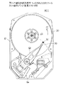
図3は上記構成の磁気抵抗効果型ヘッド30が組み込まれた磁気ディスク装置60を示す。磁気ディスク装置60は、ハウジング61の内部に、磁気ディスク20、この磁気ディスク20を矢印CC方向に回転させるスピンドルモータ68、回動アーム63、回動アーム63の先端の磁気抵抗効果型ヘッド30、回動アーム63を回動させるボイスコイルモータ64等を有する構成である。
【0033】
次に、図4(A)乃至(G)を参照して、上記磁気ディスク装置60の動作時における上記磁気抵抗効果型ヘッド30の段差52の作用について説明する。
図4(A)に示すように、磁気ディスク20が矢印CC方向に回転すると空気流21が発生し、磁気抵抗効果型ヘッド30は、この空気流21の作用で、浮上量h、浮上角αで(磁気抵抗効果素子43側が下がった姿勢で)磁気ディスク20の上面20aから浮上し続け、所望のトラックにアクセスして信号の読み書きを行う。
【0034】
図4(B),(D),(F)に示すように、磁気ディスク20は、製造工程との関係で、上面20aから突き出した大きさの異なる微小突起21−1,21−2,21−3等を有する。微小突起21−1は、突き出し寸法b1が浮上量hより小さいものである。微小突起21−2は、突き出し寸法b2が浮上量hよと略同じものである。微小突起21−3は、突き出し寸法b3が浮上量hより寸法A大きいものである。
【0035】
微小突起21−1は、図4(B)に示すように、膜状素子構造部34の端面51に衝突することなく磁気抵抗効果型ヘッド30の下側を通り抜ける。よって、読みだし信号のエンベロープは、図4(C)に示す如くになり、サーマルアスペリティによる信号異常は発生しない。
微小突起21−2は、図4(D)に示すように、膜状素子構造部34の端面51に衝突するけれども、衝突する個所は、端面51のうち磁気抵抗効果素子43より後方側の部分51aである。即ち、微小突起21−2は磁気抵抗効果素子43に衝突しない。このため、よって、読みだし信号のエンベロープは、図4(E)に示す如くになり、サーマルアスペリティによる信号異常は発生しない。
【0036】
大き目の微小突起21−3の場合は、図4(F)に示すように、スライダ33の浮上面33dのうち角部33gの付近に衝突し、磁気抵抗効果型ヘッド30は一旦押し上げられ、その後に下動する。この下動するときに、磁気抵抗効果素子43が微小突起21−3に衝突することが起きる場合がある。磁気抵抗効果素子43が微小突起21−3に衝突したとしても、微小突起が磁気抵抗効果素子を直撃した場合よりも衝突のエネルギーは遙かに小さい。このため、読みだし信号のエンベロープは、図4(G)に示す如くになり、サーマルアスペリティによる信号異常は発生したとしても小さい。
【0037】
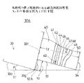
〔第2実施例〕
図5は、本発明の第2実施例になる磁気抵抗効果型ヘッド30Aを示す。図5中、図1に示す構成部分と同じ構成部分には同じ符号を付す。
膜状素子構造部34の端面51は、浮上面33dに対して段差寸法Y2の段差52Aを有している。ここで、段差52Aの大きさ、即ち、段差寸法Y2は、磁気抵抗効果型ヘッド30の浮上角をαラジアン、膜状素子構造部34の厚さをt2とした場合に、浮上角αが相当に小さいため、t2×tanαで表される大きさと同じかこれより大きい。即ち、Y2≧t2×tanαである。段差寸法Y2は、前記の段差寸法Y1より大きい。
【0038】
よって、微小突起21−2は、図6(A)に示すように、微小突起21−1の場合と同じく、膜状素子構造部34の端面51に衝突することなく磁気抵抗効果型ヘッド30の下側を通り抜ける。よって、読みだし信号のエンベロープは、図6(B)に示す如くになり、サーマルアスペリティによる信号異常は発生しない。
【0039】
大き目の微小突起21−3の場合は、図6(C)に示すように、スライダ33の浮上面33dのうち角部33gの付近に衝突し、磁気抵抗効果型ヘッド30は一旦押し上げられ、その後に下動する。段差寸法Y2が前記の段差寸法Y1より大きいため、微小突起21−3が端面51に衝突する位置は後方にずれる。よって、この下動するときに、磁気抵抗効果素子43が微小突起21−3に衝突することが起きる確率は低下する。また、磁気抵抗効果素子43が微小突起21−3に衝突したとしても、微小突起が磁気抵抗効果素子を直撃した場合よりも衝突のエネルギーは遙かに小さい。このため、読みだし信号のエンベロープは、図6(D)に示す如くになり、サーマルアスペリティによる信号異常は発生したとしても小さい。従って、サーマルアスペリティによる信号異常の程度を、信号処理回路による修正可能範囲にすることが出来、再生復調信号への影響を小さくすることが出来る。
【0040】
〔第3実施例〕
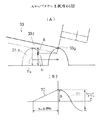
図7(A)は、本発明の第3実施例になる磁気抵抗効果型ヘッド30Bを示す。図7中、図1に示す構成部分と同じ構成部分には同じ符号を付す。磁気抵抗効果型ヘッド30Bは、膜状素子構造部34の熱膨張を考慮した構成である。
磁気抵抗効果型ヘッド30Bの使用中に膜状素子構造部34の温度が上昇する場合がある。膜状素子構造部34の温度が上昇すると、図7(B)に示すように膜状素子構造部34が熱膨張し、端面51が盛り上がるように変形する。
【0041】
端面51のうち磁気抵抗効果素子43の部位の盛り上がり変形量は、Nhである。
図7(A)に示すように、膜状素子構造部34の端面51は、浮上面33dに対して段差寸法Y3の段差52Bを有している。ここで、段差52Bの大きさ、即ち、段差寸法Y3は、前記の段差寸法Y1に上記の盛り上がり変形量Nhを加えた値としてある。即ち、Y3≧Y1+Nhである。
【0042】
この磁気抵抗効果型ヘッド30Bによれば、使用中に膜状素子構造部34の温度が上昇した場合にも、磁気抵抗効果素子43は、図7(B)に示すように、仮想面55近くまでは突き出すけれども、それ以上には突き出さない。よって、膜状素子構造部34が変形しても磁気ディスク20の微小突起が磁気抵抗効果素子43を直撃することは起きず、サーマルアスペリティによる信号異常も発生しにくい。
【0043】
この磁気抵抗効果型ヘッド30Bは、使用される環境が温度の高い環境である場合に有効である。
〔第4実施例〕
図8は、本発明の第4実施例になる磁気抵抗効果型ヘッド30Cを示す。図8中、図1に示す構成部分と同じ構成部分には同じ符号を付す。磁気抵抗効果型ヘッド30Cは、ステップダウンを考慮した構成である。
【0044】
図8に示すように、膜状素子構造部34の端面51は、浮上面33dに対して段差寸法Y4の段差52Cを有している。ここで、段差52Cの大きさ、即ち、段差寸法Y4は、前記の段差寸法Y1にステップダウン分(浮上変化分)Zを加えた値としてある。即ち、Y4≧Y1+Zである。
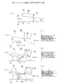
図9(A)に示すように、大き目の微小突起21−3の場合は、スライダ33の浮上面33dのうち角部33gの付近に衝突し、磁気抵抗効果型ヘッド30は一旦押し上げられ、その後に下動(ステップダウン)する。図9(B)は、このときの磁気抵抗効果型ヘッド30の動きを示す。線70は、磁気抵抗効果型ヘッド30が微小突起21−3によって押し上げられるときの動きを示す。線71は、微小突起21−3がスライダ33の角部(アルチックエッジ)33gを通り越した後の、磁気抵抗効果型ヘッド30の動きを示す。線71は、Z=A×{1−sin(π/2+X)}で表される曲線である。ここで、Aは微小突起21−3の浮上量hより更に突き出た寸法である。Xは磁気抵抗効果型ヘッド30の浮上追従時の位相であり、2π×t1/(U/2fo)で表される。Uは磁気ディスク62の磁気抵抗効果型ヘッド30の個所の周速度、foは磁気抵抗効果型ヘッド30の共振周波数である。
【0045】
本実施例の磁気抵抗効果型ヘッド30Cは、大き目の微小突起21−3がスライダ33の浮上面33dのうち角部33gの付近に衝突し、磁気抵抗効果型ヘッド30が一旦押し上げられた後に下動(ステップダウン)する動きをする過程においても、磁気抵抗効果素子43が微小突起21−3と衝突することは回避され、サーマルアスペリティによる信号異常は発生しない。
【0046】
〔第5実施例〕
図10は、本発明の第5実施例になる磁気抵抗効果型ヘッド30Dを示す。図8中、図1に示す構成部分と同じ構成部分には同じ符号を付す。磁気抵抗効果型ヘッド30Dは、膜状素子構造部34の熱膨張、及び上記のステップダウンの両方を考慮した構成である。
【0047】
図10に示すように、膜状素子構造部34の端面51は、浮上面33dに対して段差寸法Y5の段差52Dを有している。ここで、段差52Dの大きさ、即ち、段差寸法Y5は、前記の段差寸法Y1に、盛り上がり変形量Nhとステップダウン分(浮上変化分)Zを加えた値としてある。即ち、Y5≧Y1+Nh+Zである。
【0048】
本実施例の磁気抵抗効果型ヘッド30Dによれば、温度の高い環境で使用され、大き目の微小突起21−3に遭遇した場合でも、サーマルアスペリティによる信号異常は発生しない。
また、磁気ディスク装置は、上記の磁気抵抗効果型ヘッド30A〜30Dのうち何れかの磁気抵抗効果型ヘッドを使用した構成と出来る。
【0049】
図11は、本発明者が実験を行った結果である、膜状素子構造部34の端面51の浮上面33dに対する段差寸法とサーマルアスペリティの出力との関係を示す。同図より、段差寸法が増えるとサーマルアスペリティの出力が減少していることが分かる。
なお、上記段差をもうけると、磁気抵抗効果素子43の端面と磁気ディスクの表面との距離が増すけれども、段差寸法は大きくはなく、磁気抵抗効果素子43による磁気ディスク上の記録信号を再生することに対する影響は殆ど無い。よって、磁気ディスク上の記録信号は良好に再生される。
【0050】
また、図1の段差Y1に代えて図5の段差Y2を基準としてもよい。この場合には、図7に示す上記第3実施例において、段差Y3’は、Y3’≧Y2+Nhとなる。
また、図8に示す上記第4実施例において、段差Y4’は、Y4’≧Y2+Zとなる。
【0051】
また、図10に示す上記第5実施例において、段差Y5’は、Y5’≧Y2+Nh+Zとなる。
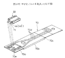
図12は図1及び図2に示す構成の磁気抵抗効果型ヘッド30が組み込まれた別の磁気ディスク装置60Aを示す。図12中、図3に示す構成部分と同じ部分に同じ符号を付す。回動アーム63の先端には、図13のジンバル部一体型サスペンション70がカシメて固定してある。このジンバル部一体型サスペンション70のジンバル部70aに、磁気抵抗効果型ヘッド30が固定してある。
【0052】
ジンバル部一体型サスペンション70は、図13に示すように、先端側にジンバル部70aを有し、中央部の両側に剛性をうるためのリブ70bを有し、基部寄り側にR曲げ部70cを有し、上面に基部からジンバル部70aまで延在する4本の配線パターン70dを有する構成である。4本の配線パターン70dのうち2本が磁気抵抗効果素子用であり、残りの2本がインダクティブヘッド用である。
【0053】
磁気抵抗効果型ヘッド30はジンバル部70aに接着されている。4本の配線パターン70dの端の端子70eと磁気抵抗効果型ヘッド30の端子部44’、48’とが、金ボール71によって接続されている。
磁気抵抗効果型ヘッド30はR曲げ部70cの弾性によって磁気ディスク側に押しつけられている。
【0054】
【発明の効果】
以上のように、請求項1乃至請求項13の発明によれば、膜状素子構造部のスライダの浮上面に対向する端面が、スライダの浮上面より、磁気ディスクの微小突起が端面に衝突することを回避できる大きさの所定の段差寸法後退した構成としたため、磁気ディスク上に浮上量を越える高さの大きめの微小突起がある場合でも、この大きめの微小突起が磁気抵抗効果素子に衝突することが効果的に回避され、サーマルアスペリティによる信号異常の発生を効果的に防止出来る。よって、近年の高密度記録化に伴って磁気抵抗効果型ヘッドの磁気ディスクに対する浮上量を小さくしようとする場合に、サーマルアスペリティによる信号異常の発生を防止する対策として効果がある。
【0055】
請求項2、7、11の発明によれば、段差寸法が膜状素子構造部が熱膨張したときの上記端面のうち磁気抵抗効果素子の部位の盛り上がり変形量を考慮した構成であるため、使用される環境が温度の高い環境である場合に有効である。
請求項3、9、12の発明によれば、段差寸法がスライダが上記磁気ディスク上の微小突起を相対的に乗り越えたときのステップダウン分を考慮した構成であるため、大きめの微小突起が磁気抵抗効果素子に衝突することがより効果的に回避出来る。
【0056】
請求項4、10、13の発明によれば、段差寸法が膜状素子構造部が熱膨張したときの上記端面のうち磁気抵抗効果素子の部位の盛り上がり変形量とスライダが上記磁気ディスク上の微小突起を相対的に乗り越えたときのステップダウン分との両方を考慮した構成であるため、温度の高い環境で使用されているときにも、大きめの微小突起が磁気抵抗効果素子に衝突することがより効果的に回避出来る。
【0057】
請求項14、15の発明によれば、サーマルアスペリティを回避出来、よって、信号品質を向上できる磁気ディスク装置を実現出来る。またサーマルアスペリティを回避できるため、磁気抵抗効果型ヘッドを磁気ディスクの磁性膜により近づけて低浮上化が可能になり、より一層の高密度記録が可能となる磁気ディスク装置を実現出来る。
【図面の簡単な説明】
【図1】本発明の第1実施例になる磁気抵抗効果型ヘッドの要部を拡大して示す図である。
【図2】本発明の第1実施例になる磁気抵抗効果型ヘッドを示す図である。
【図3】図1の磁気抵抗効果型ヘッドが組み込まれている磁気ディスク装置を示す図である。
【図4】図1の磁気抵抗効果型ヘッドの段差の作用を説明する図である。
【図5】本発明の第2実施例になる磁気抵抗効果型ヘッドの要部を拡大して示す図である。
【図6】図5の磁気抵抗効果型ヘッドの段差の作用を説明する図である。
【図7】本発明の第3実施例になる磁気抵抗効果型ヘッドの要部を拡大して示す図である。
【図8】本発明の第4実施例になる磁気抵抗効果型ヘッドの要部を拡大して示す図である。
【図9】ステップダウンを説明する図である。
【図10】本発明の第5実施例になる磁気抵抗効果型ヘッドの要部を拡大して示す図である。
【図11】段差寸法とサーマルアスペリティの出力との関係を示す図である。
【図12】図1の磁気抵抗効果型ヘッドが組み込まれている別の磁気ディスク装置を示す図である。
【図13】図12中、サスペンションを拡大して示す図である。
【図14】従来の磁気抵抗効果型ヘッドを示す図である。
【符号の説明】
30,30A,30B,30C,30D 磁気抵抗効果型ヘッド
31 空気流入端
32 空気流出端
33 スライダ
33a,33b レール
33c 浅い凹部
33d,33e 浮上面
33f 空気流出端の面
33g 角部(アルチックエッジ)
34 膜状素子構造部
40、42、45、47 絶縁膜
41 下部シールド膜(磁性膜)
43 膜状の磁気抵抗効果素子
44 膜状の導電部材
46 下部磁性膜
48 膜状のコイル
49 上部磁性膜
50 保護膜
51 端面
52、52A,52B,52C,52D 段差
55 仮想面
60、60A 磁気ディスク装置
63 回動アーム
64 ボイスコイルモータ
68 スピンドルモータ
70 ジンバル部一体型サスペンション
70d 配線パターン
70a ジンバル部
70e 端子
71 金ボール[0001]
BACKGROUND OF THE INVENTION
The present invention relates to a magnetoresistive head used in a magnetic disk device that records and reproduces information on a magnetic disk.
In recent years, magnetic disks have been reduced in diameter and magnetic disk devices have been downsized. When the diameter of the magnetic disk is reduced, the relative speed between the magnetic disk and the head decreases. The magnetoresistive head reads the signal on the magnetic disk based on the principle of the magnetoresistive effect. Even if the relative speed between the magnetic disk and the magnetoresistive head is not large, a read signal with a large output level is output. Therefore, the magnetic disk device is suitable for downsizing.
[0002]
This magnetoresistive head has a problem of signal abnormality due to thermal asperity described later, and it is necessary to solve this problem.
In addition, with the recent high density recording, the flying height of the magnetoresistive head with respect to the magnetic disk has been reduced. As the flying height decreases, the degree of signal abnormality due to thermal asperity tends to increase, so it is important to solve this problem.
[0003]
[Prior art]
14A and 14B show a conventional
[0004]
The
[0005]
In order to prevent the magnetic head from adsorbing to the magnetic disk when the magnetic head starts and stops contact, the magnetic disk is manufactured by texturing the substrate and forming a film on the textured surface. . The surface roughness Ra of the magnetic disk is about 10 to 50 mm so as not to hit the flying magnetoresistive head.
[0006]
[Problems to be solved by the invention]
The texturing is mechanically formed or formed by a laser, and the roughness Ra of the surface of the magnetic disk varies. As shown in FIG. 14B, there may be a case where a
With recent high-density recording, the flying height h of the magnetoresistive head with respect to the magnetic disk has decreased to 30 to 50 nm, and these
[0007]
When the
[0008]
Conventionally, as a countermeasure against thermal asperity, it has been adopted to improve the surface quality of a magnetic disk or to provide a signal processing circuit for suppressing signal abnormality due to thermal asperity.
When the flying height h of the
[0009]
SUMMARY OF THE INVENTION Accordingly, it is an object of the present invention to provide a magnetoresistive head that has solved the above problems and a magnetic disk device having the same.
[0010]
[Means for Solving the Problems]
According to the first aspect of the present invention, there is provided a slider that floats at a predetermined flying angle with respect to a magnetic disk, and a film that includes a magnetoresistive element for reproducing information, which is formed at the air outflow end of the slider. In a magnetoresistive head having an element structure,
The end surface on the same side as the air bearing surface of the slider of the film element structure portion is at a position recessed by a predetermined step size from the air bearing surface of the slider,
The predetermined step size is an imaginary plane parallel to the magnetic disk passing through the corner of the air outflow end of the slider as a posture in which the magnetoresistive head is inclined at the predetermined flying angle with respect to the magnetic disk. In consideration of the above, the end of the magnetoresistive effect element facing the end face has a size sufficient to be positioned above the virtual face.
[0012]
ClaimItem 2The present invention relates to a slider that floats at a predetermined flying angle with respect to a magnetic disk, and a film element structure portion that is formed at an air outflow end of the slider and includes a magnetoresistive effect element for reproducing information, In the magnetoresistive head having the above structure, the end surface of the film element structure portion on the same side as the air bearing surface of the slider is at a position recessed by a predetermined step size from the air bearing surface of the slider,
The predetermined step size is an imaginary plane parallel to the magnetic disk passing through the corner of the air outflow end of the slider as a posture in which the magnetoresistive head is inclined at the predetermined flying angle with respect to the magnetic disk. When the film-like element structure is thermally expanded to a dimension sufficient to position the end facing the end face of the magnetoresistive element above the virtual plane, the end face rises and deforms. It is set as the structure which has the dimension which added quantity.
[0013]
ClaimItem 3The present invention relates to a slider that floats at a predetermined flying angle with respect to a magnetic disk, and a film element structure portion that is formed at an air outflow end of the slider and includes a magnetoresistive effect element for reproducing information, In the magnetoresistive head having the above structure, the end surface of the film element structure portion on the same side as the air bearing surface of the slider is at a position recessed by a predetermined step size from the air bearing surface of the slider,
The predetermined step size is an imaginary plane parallel to the magnetic disk passing through the corner of the air outflow end of the slider as a posture in which the magnetoresistive head is inclined at the predetermined flying angle with respect to the magnetic disk. When the slider has moved over the small protrusion on the magnetic disk so that the end facing the end surface of the magnetoresistive element is positioned above the imaginary surface. It is set as the structure which has the dimension which added the part for this step-down.
[0014]
ClaimItem 4The present invention relates to a slider that floats at a predetermined flying angle with respect to a magnetic disk, and a film element structure portion that is formed at an air outflow end of the slider and includes a magnetoresistive effect element for reproducing information, In a magnetoresistive head having
The end surface on the same side as the air bearing surface of the slider of the film element structure portion is at a position recessed by a predetermined step size from the air bearing surface of the slider,
The predetermined step size is an imaginary plane parallel to the magnetic disk passing through the corner of the air outflow end of the slider as a posture in which the magnetoresistive head is inclined at the predetermined flying angle with respect to the magnetic disk. When the film-like element structure is thermally expanded to a dimension sufficient to position the end facing the end face of the magnetoresistive element above the virtual plane, the end face rises and deforms. In this configuration, the amount and the step-down amount when the slider relatively gets over the minute protrusion on the magnetic disk are added.
[0015]
ClaimItem 5The present invention relates to a slider that floats at a predetermined flying angle with respect to a magnetic disk, and a film element structure portion that is formed at an air outflow end of the slider and includes a magnetoresistive effect element for reproducing information, In a magnetoresistive head having
The end surface on the same side as the air bearing surface of the slider of the film element structure portion is at a position recessed by a predetermined step size from the air bearing surface of the slider,
The predetermined step size is an imaginary plane parallel to the magnetic disk passing through the corner of the air outflow end of the slider as a posture in which the magnetoresistive head is inclined at the predetermined flying angle with respect to the magnetic disk. In consideration of the above, it is configured that the end of the air outflow end of the end face of the film element structure portion has a dimension sufficient to be positioned above the virtual plane.
[0016]
ClaimItem 6The present invention relates to a magnetoresistive element having a slider that is inclined and floats with respect to a magnetic disk, and a film element structure portion that is formed at an air outflow end of the slider and includes a magnetoresistive element for reproducing information. In the effect type head,
The dimension Y1 of the step which is retreated from the air bearing surface of the slider on the same side as the air bearing surface of the slider of the film element structure portion is:
Y1 ≧ t1 × tan α
(Here, t1 is the distance from the air outflow end surface of the slider to the magnetoresistive element, and α is the flying angle of the magnetoresistive head.)
It is set as the structure which is the magnitude | size which satisfy | fills.
[0017]
ClaimItem 7The present invention relates to a magnetoresistive element having a slider that is inclined and floats with respect to a magnetic disk, and a film element structure portion that is formed at an air outflow end of the slider and includes a magnetoresistive element for reproducing information. In the effect type head,
The step dimension Y2 of the step of the film-like element structure portion retreated from the flying surface of the slider on the same side as the flying surface of the slider is:
Y2 ≧ t2 × tanα
(Here, t2 is the thickness of the film element structure, and α is the flying angle of the magnetoresistive head.)
It is set as the structure which is the magnitude | size which satisfy | fills.
[0018]
ClaimItem 8The present invention relates to a magnetoresistive element having a slider that is inclined and floats with respect to a magnetic disk, and a film element structure portion that is formed at an air outflow end of the slider and includes a magnetoresistive element for reproducing information. In the effect type head,
The step size Y3 of the step of the film-like element structure portion retreated from the flying surface of the slider on the same side as the flying surface of the slider is:
Y3 ≧ (t1 × tan α) + Nh
(Where t1 is the distance from the air outflow end surface of the slider to the magnetoresistive element, α is the flying angle of the magnetoresistive head, and Nh is the amount of bulging deformation due to thermal expansion of the film element structure) .)
It is set as the structure which is the magnitude | size which satisfy | fills.
[0019]
ClaimItem 9The present invention relates to a magnetoresistive element having a slider that is inclined and floats with respect to a magnetic disk, and a film element structure portion that is formed at an air outflow end of the slider and includes a magnetoresistive element for reproducing information. In the effect type head,
The step dimension Y4 of the step of the film-like element structure part retreated from the flying surface of the slider on the same side as the flying surface of the slider is:
Y4 ≧ (t1 × tan α) + Z
(Where t1 is the distance from the air outflow end surface of the slider to the magnetoresistive effect element, α is the flying angle of the magnetoresistive head, and Z is the magnetoresistive head formed by a minute projection on the magnetic disk. (It is the distance that has been stepped down after being pushed up once.)
It is set as the structure which is the magnitude | size which satisfy | fills.
[0020]
ClaimItem 10The present invention relates to a magnetoresistive element having a slider that is inclined and floats with respect to a magnetic disk, and a film element structure portion that is formed at an air outflow end of the slider and includes a magnetoresistive element for reproducing information. In the effect type head,
The dimension Y5 of the step which is retreated from the air bearing surface of the slider on the same side as the air bearing surface of the slider of the film element structure portion is:
Y5 ≧ (t1 × tan α) + Nh + Z
(Where t1 is the distance from the air outflow end surface of the slider to the magnetoresistive element, α is the flying angle of the magnetoresistive head, and Nh is the amount of bulging deformation due to thermal expansion of the film element structure) , Z is a distance in which the magnetoresistive head is stepped down after being once pushed up by the minute protrusions of the magnetic disk.
It is set as the structure which is the magnitude | size which satisfy | fills.
[0021]
ClaimItem 11The present invention relates to a magnetoresistive element having a slider that is inclined and floats with respect to a magnetic disk, and a film element structure portion that is formed at an air outflow end of the slider and includes a magnetoresistive element for reproducing information. In the effect type head,
The step dimension Y3 'of the step of the film-like element structure portion retreated from the air bearing surface of the slider on the same side as the air bearing surface of the slider is:
Y3 '≧ (t2 × tan α) + Nh
Where t2 is the thickness of the film element structure, α is the flying angle of the magnetoresistive head, and Nh is the amount of bulge deformation due to thermal expansion of the film element structure. It is set as the structure which is.
[0022]
ClaimItem 12The present invention relates to a magnetoresistive element having a slider that is inclined and floats with respect to a magnetic disk, and a film element structure portion that is formed at an air outflow end of the slider and includes a magnetoresistive element for reproducing information. In the effect type head,
The step dimension Y4 'of the step of the film-like element structure portion retreated from the slider floating surface on the same side as the slider floating surface is as follows.
Y4 '≧ (t2 × tan α) + Z
(Where t2 is the thickness of the film element structure portion, α is the flying angle of the magnetoresistive head, and Z is lowered after the magnetoresistive head is once pushed up by the minute protrusions of the magnetic disk. And stepped down.)
It is set as the structure which is the magnitude | size which satisfy | fills.
[0023]
ClaimItem 13The present invention relates to a magnetoresistive element having a slider that is inclined and floats with respect to a magnetic disk, and a film element structure portion that is formed at an air outflow end of the slider and includes a magnetoresistive element for reproducing information. In the effect type head,
The step dimension Y5 'of the step of the film-like element structure portion retreated from the slider floating surface on the same side as the slider floating surface is as follows.
Y5 '≧ (t2 × tan α) + Nh + Z
(Where t2 is the thickness of the film element structure, α is the flying angle of the magnetoresistive head, Nh is the amount of bulging deformation due to thermal expansion of the film element structure, and Z is the magnetoresistive head. ) Is a distance that has been stepped down after being pushed up once by a minute protrusion on the magnetic disk.
It is set as the structure which is the magnitude | size which satisfy | fills.
[0024]
ClaimItem 14The invention comprises a rotating magnetic disk;
ClaimItem 15Invention claimsIn item 14The support means is formed of a suspension on which a wiring pattern is formed and a magnetoresistive head is fixed, and a terminal portion of the magnetoresistive head and a terminal of the wiring pattern are formed by a gold ball. This is a connected configuration.
[0025]
DETAILED DESCRIPTION OF THE INVENTION
[First embodiment]
1 and 2A and 2B show a
[0026]
The
The
[0027]
33 g is a corner (altic edge) formed by the
The film
[0028]
On the
[0029]
The lower
It becomes.
The
[0030]
Here, the size of the
[0031]
The flying angle α of the
Referring to FIG. 1, the step size Y1 is such that the
[0032]
The
FIG. 3 shows a
[0033]
Next, with reference to FIGS. 4A to 4G, the operation of the
As shown in FIG. 4A, when the
[0034]
As shown in FIGS. 4B, 4D, and 4F, the
[0035]
As shown in FIG. 4B, the minute protrusion 21-1 passes through the lower side of the
As shown in FIG. 4D, the microprojection 21-2 collides with the
[0036]
In the case of the large microprojection 21-3, as shown in FIG. 4F, it collides with the vicinity of the
[0037]
[Second Embodiment]
FIG. 5 shows a
The end face 51 of the
[0038]
Therefore, as shown in FIG. 6A, the microprojection 21-2 does not collide with the
[0039]
In the case of the large microprojection 21-3, as shown in FIG. 6C, it collides with the vicinity of the
[0040]
[Third embodiment]
FIG. 7A shows a
During use of the
[0041]
The rising deformation amount of the part of the
As shown in FIG. 7A, the
[0042]
According to the
[0043]
This
[Fourth embodiment]
FIG. 8 shows a
[0044]
As shown in FIG. 8, the
As shown in FIG. 9A, in the case of the large microprojection 21-3, it collides with the vicinity of the
[0045]
In the
[0046]
[Fifth embodiment]
FIG. 10 shows a
[0047]
As shown in FIG. 10, the
[0048]
According to the
Further, the magnetic disk device can be configured to use any one of the magnetoresistive heads 30A to 30D.
[0049]
FIG. 11 shows the relationship between the step size with respect to the
If the step is provided, the distance between the end surface of the
[0050]
Moreover, it is good also considering the level | step difference Y2 of FIG. 5 instead of the level | step difference Y1 of FIG. In this case, in the third embodiment shown in FIG. 7, the step Y3 'satisfies Y3'≥Y2 + Nh.
Further, in the fourth embodiment shown in FIG. 8, the step Y4 'satisfies Y4'≥Y2 + Z.
[0051]
Further, in the fifth embodiment shown in FIG. 10, the step Y5 'is Y5'≥Y2 + Nh + Z.
FIG. 12 shows another
[0052]
As shown in FIG. 13, the gimbal-integrated
[0053]
The
The
[0054]
【The invention's effect】
As described above,
[0055]
ClaimTerms 2, 7, and 11According to the invention, since the step size is a configuration that takes into account the bulging deformation amount of the portion of the magnetoresistive effect element in the end face when the film element structure portion is thermally expanded, the environment used is a high temperature environment. It is effective when
ClaimItem 3, 9, 12According to the invention, since the step size takes into account the step-down amount when the slider relatively moves over the minute protrusion on the magnetic disk, the larger minute protrusion may collide with the magnetoresistive element. It can be avoided more effectively.
[0056]
[0057]
ClaimItem 14, 15According to the present invention, it is possible to realize a magnetic disk device that can avoid thermal asperity and thus improve signal quality. In addition, since thermal asperity can be avoided, the magnetoresistive head can be brought closer to the magnetic film of the magnetic disk to lower the flying height, thereby realizing a magnetic disk device that can achieve higher density recording.
[Brief description of the drawings]
FIG. 1 is an enlarged view showing a main part of a magnetoresistive head according to a first embodiment of the present invention.
FIG. 2 is a diagram showing a magnetoresistive head according to a first embodiment of the invention.
FIG. 3 is a diagram showing a magnetic disk device in which the magnetoresistive head of FIG. 1 is incorporated.
4 is a diagram for explaining the action of a step of the magnetoresistive head of FIG. 1; FIG.
FIG. 5 is an enlarged view showing a main part of a magnetoresistive head according to a second embodiment of the invention.
6 is a diagram for explaining the action of a step in the magnetoresistive head of FIG. 5;
FIG. 7 is an enlarged view showing a main part of a magnetoresistive head according to a third embodiment of the invention.
FIG. 8 is an enlarged view showing a main part of a magnetoresistive head according to a fourth embodiment of the invention.
FIG. 9 is a diagram illustrating step down.
FIG. 10 is an enlarged view showing a main part of a magnetoresistive head according to a fifth embodiment of the invention.
FIG. 11 is a diagram illustrating a relationship between a step size and an output of thermal asperity.
12 is a diagram showing another magnetic disk device in which the magnetoresistive head of FIG. 1 is incorporated. FIG.
13 is an enlarged view of the suspension in FIG.
FIG. 14 is a diagram showing a conventional magnetoresistive head.
[Explanation of symbols]
30, 30A, 30B, 30C, 30D Magnetoresistive head
31 Air inflow end
32 Air outflow end
33 Slider
33a, 33b rail
33c Shallow recess
33d, 33e Air bearing surface
33f Air outflow end surface
33g corner (altic edge)
34 Membrane element structure
40, 42, 45, 47 Insulating film
41 Lower shield film (magnetic film)
43 Film-like magnetoresistive effect element
44 Film-like conductive member
46 Lower magnetic film
48 Membrane coil
49 Upper magnetic film
50 Protective film
51 End face
52, 52A, 52B, 52C, 52D
55 Virtual plane
60, 60A magnetic disk drive
63 Rotating arm
64 voice coil motor
68 spindle motor
70 Gimbal integrated suspension
70d wiring pattern
70a Gimbal
70e terminal
71 gold balls
Claims (15)
該膜状素子構造部の該スライダの浮上面と同じ側の端面が、該スライダの浮上面より所定の段差寸法後退した位置にあり、
該所定の段差寸法が、上記磁気抵抗効果型ヘッドを上記磁気ディスクに対して上記の所定の浮上角傾斜させた姿勢として上記スライダの空気流出端の角部を通り上記磁気ディスクと平行な仮想面を考えた場合に、上記磁気抵抗効果素子の上記端面に臨んでいる端部を上記仮想面より上側に位置させるに足る寸法を有する構成としたことを特徴とする磁気抵抗効果型ヘッド。A magnetic element having a slider that rises at a predetermined flying angle with respect to the magnetic disk, and a film-like element structure portion that is formed at the air outflow end of the slider and includes a magnetoresistive element for reproducing information. In the resistance effect type head,
The end surface on the same side as the air bearing surface of the slider of the film element structure portion is at a position recessed by a predetermined step size from the air bearing surface of the slider,
The predetermined step size is an imaginary plane parallel to the magnetic disk passing through the corner of the air outflow end of the slider as a posture in which the magnetoresistive head is inclined at the predetermined flying angle with respect to the magnetic disk. When considering the above, the magnetoresistive head is characterized in that the end of the magnetoresistive element facing the end face has a size sufficient to be positioned above the virtual plane.
該膜状素子構造部の該スライダの浮上面と同じ側の端面が、該スライダの浮上面より所定の段差寸法後退した位置にあり、
該所定の段差寸法が、上記磁気抵抗効果型ヘッドを上記磁気ディスクに対して上記の所定の浮上角傾斜させた姿勢として上記スライダの空気流出端の角部を通り上記磁気ディスクと平行な仮想面を考えた場合に、磁気抵抗効果素子の上記端面に臨んでいる端部を上記仮想面より上側に位置させるに足る寸法に、上記膜状素子構造部が熱膨張したときの上記端面の盛り上がり変形量を加算した寸法を有する構成としたことを特徴とする磁気抵抗効果型ヘッド。A magnetic element having a slider that rises at a predetermined flying angle with respect to the magnetic disk, and a film-like element structure portion that is formed at the air outflow end of the slider and includes a magnetoresistive element for reproducing information. In the resistance effect type head,
The end surface on the same side as the air bearing surface of the slider of the film element structure portion is at a position recessed by a predetermined step size from the air bearing surface of the slider,
The predetermined step size is an imaginary plane parallel to the magnetic disk passing through the corner of the air outflow end of the slider as a posture in which the magnetoresistive head is inclined at the predetermined flying angle with respect to the magnetic disk. When the film-like element structure is thermally expanded to a dimension sufficient to position the end facing the end face of the magnetoresistive element above the virtual plane, the end face rises and deforms. A magnetoresistive head characterized by having a configuration with an added quantity.
該膜状素子構造部の該スライダの浮上面と同じ側の端面が、該スライダの浮上面より所定の段差寸法後退した位置にあり、
該所定の段差寸法が、上記磁気抵抗効果型ヘッドを上記磁気ディスクに対して上記の所定の浮上角傾斜させた姿勢として上記スライダの空気流出端の角部を通り上記磁気ディスクと平行な仮想面を考えた場合に、磁気抵抗効果素子の上記端面に臨んでいる端部を上記仮想面より上側に位置させるに足る寸法に、上記スライダが上記磁気ディスク上の微小突起を相対的に乗り越えたときのステップダウン分を加算した寸法を有する構成としたことを特徴とする磁気抵抗効果型ヘッド。A magnetic element having a slider that rises at a predetermined flying angle with respect to the magnetic disk, and a film-like element structure portion that is formed at the air outflow end of the slider and includes a magnetoresistive element for reproducing information. In the resistance effect type head,
The end surface on the same side as the air bearing surface of the slider of the film element structure portion is at a position recessed by a predetermined step size from the air bearing surface of the slider,
The predetermined step size is an imaginary plane parallel to the magnetic disk passing through the corner of the air outflow end of the slider as a posture in which the magnetoresistive head is inclined at the predetermined flying angle with respect to the magnetic disk. When the slider has moved over the small protrusion on the magnetic disk so that the end facing the end surface of the magnetoresistive element is positioned above the imaginary surface. A magnetoresistive head characterized by having a size obtained by adding the amount of step down.
該膜状素子構造部の該スライダの浮上面と同じ側の端面が、該スライダの浮上面より所定の段差寸法後退した位置にあり、
該所定の段差寸法が、上記磁気抵抗効果型ヘッドを上記磁気ディスクに対して上記の所定の浮上角傾斜させた姿勢として上記スライダの空気流出端の角部を通り上記磁気ディスクと平行な仮想面を考えた場合に、磁気抵抗効果素子の上記端面に臨んでいる端部を上記仮想面より上側に位置させるに足る寸法に、上記膜状素子構造部が熱膨張したときの上記端面の盛り上がり変形量と上記スライダが上記磁気ディスク上の微小突起を相対的に乗り越えたときのステップダウン分とを加算した寸法を有する構成としたことを特徴とする磁気抵抗効果型ヘッド。A magnetic element having a slider that rises at a predetermined flying angle with respect to the magnetic disk, and a film-like element structure portion that is formed at the air outflow end of the slider and includes a magnetoresistive element for reproducing information. In the resistance effect type head,
The end surface on the same side as the air bearing surface of the slider of the film element structure portion is at a position recessed by a predetermined step size from the air bearing surface of the slider,
The predetermined step size is an imaginary plane parallel to the magnetic disk passing through the corner of the air outflow end of the slider as a posture in which the magnetoresistive head is inclined at the predetermined flying angle with respect to the magnetic disk. When the film-like element structure is thermally expanded to a dimension sufficient to position the end facing the end face of the magnetoresistive element above the virtual plane, the end face rises and deforms. A magnetoresistive head having a size obtained by adding an amount and a step-down amount when the slider relatively gets over a minute protrusion on the magnetic disk.
該膜状素子構造部の該スライダの浮上面と同じ側の端面が、該スライダの浮上面より所定の段差寸法後退した位置にあり、
該所定の段差寸法が、上記磁気抵抗効果型ヘッドを上記磁気ディスクに対して上記の所定の浮上角傾斜させた姿勢として上記スライダの空気流出端の角部を通り上記磁気ディスクと平行な仮想面を考えた場合に、該膜状素子構造部の上記端面の空気流出端の端部を上記仮想面より上側に位置させるに足る寸法を有する構成としたことを特徴とする磁気抵抗効果型ヘッド。A magnetic element having a slider that rises at a predetermined flying angle with respect to the magnetic disk, and a film-like element structure portion that is formed at the air outflow end of the slider and includes a magnetoresistive element for reproducing information. In the resistance effect type head,
The end surface on the same side as the air bearing surface of the slider of the film element structure portion is at a position recessed by a predetermined step size from the air bearing surface of the slider,
The predetermined step size is an imaginary plane parallel to the magnetic disk passing through the corner of the air outflow end of the slider as a posture in which the magnetoresistive head is inclined at the predetermined flying angle with respect to the magnetic disk. In consideration of the above, a magnetoresistive head having a size sufficient to position the end of the air outflow end of the end face of the film element structure portion above the imaginary plane.
該膜状素子構造部の該スライダの浮上面と同じ側の端面の該スライダの浮上面より後退した段差の寸法Y1が、
Y1≧t1×tanα
(ここで、t1は上記スライダの空気流出端の面から上記磁気抵抗効果素子までの距離、αは上記磁気抵抗効果型ヘッドの浮上角である。)
を満たす大きさである構成としたことを特徴とする磁気抵抗効果型ヘッド。A magnetoresistive head having a slider that is inclined and floats with respect to a magnetic disk, and a film element structure portion that is formed at the air outflow end of the slider and includes a magnetoresistive element for reproducing information. In
The dimension Y1 of the step which is retreated from the air bearing surface of the slider on the same side as the air bearing surface of the slider of the film element structure portion is:
Y1 ≧ t1 × tan α
(Here, t1 is the distance from the air outflow end surface of the slider to the magnetoresistive element, and α is the flying angle of the magnetoresistive head.)
A magnetoresistive head having a size satisfying the above requirements.
該膜状素子構造部の該スライダの浮上面と同じ側の端面の該スライダの浮上面より後退した段差の寸法Y2が、
Y2≧t2×tanα
(ここで、t2は上記膜状素子構造部の厚さ、αは上記磁気抵抗効果型ヘッドの浮上角である。)
を満たす大きさである構成としたことを特徴とする磁気抵抗効果型ヘッド。A magnetoresistive head having a slider that is inclined and floats with respect to a magnetic disk, and a film element structure portion that is formed at the air outflow end of the slider and includes a magnetoresistive element for reproducing information. In
The step dimension Y2 of the step of the film-like element structure portion retreated from the flying surface of the slider on the same side as the flying surface of the slider is:
Y2 ≧ t2 × tanα
(Here, t2 is the thickness of the film element structure, and α is the flying angle of the magnetoresistive head.)
A magnetoresistive head having a size satisfying the above requirements.
該膜状素子構造部の該スライダの浮上面と同じ側の端面の該スライダの浮上面より後退した段差の寸法Y3が、
Y3≧(t1×tanα)+Nh
(ここで、t1は上記スライダの空気流出端の面から上記磁気抵抗効果素子までの距離、αは上記磁気抵抗効果型ヘッドの浮上角、Nhは膜状素子構造部の熱膨張による盛り上がり変形量である。)
を満たす大きさである構成としたことを特徴とする磁気抵抗効果型ヘッド。A magnetoresistive head having a slider that is inclined and floats with respect to a magnetic disk, and a film element structure portion that is formed at the air outflow end of the slider and includes a magnetoresistive element for reproducing information. In
The step size Y3 of the step of the film-like element structure portion retreated from the flying surface of the slider on the same side as the flying surface of the slider is:
Y3 ≧ (t1 × tan α) + Nh
(Where t1 is the distance from the air outflow end surface of the slider to the magnetoresistive element, α is the flying angle of the magnetoresistive head, and Nh is the amount of bulging deformation due to thermal expansion of the film element structure) .)
A magnetoresistive head having a size satisfying the above requirements.
該膜状素子構造部の該スライダの浮上面と同じ側の端面の該スライダの浮上面より後退した段差の寸法Y4が、
Y4≧(t1×tanα)+Z
(ここで、t1は上記スライダの空気流出端の面から上記磁気抵抗効果素子までの距離、αは上記磁気抵抗効果型ヘッドの浮上角、Zは磁気抵抗効果型ヘッドが磁気ディスクの微小突起によって一旦押し上げられた後に下動してステップダウンした距離である。)
を満たす大きさである構成としたことを特徴とする磁気抵抗効果型ヘッド。A magnetoresistive head having a slider that is inclined and floats with respect to a magnetic disk, and a film element structure portion that is formed at the air outflow end of the slider and includes a magnetoresistive element for reproducing information. In
The step dimension Y4 of the step of the film-like element structure portion retreated from the slider floating surface on the same side as the slider floating surface is as follows.
Y4 ≧ (t1 × tan α) + Z
(Where t1 is the distance from the air outflow end surface of the slider to the magnetoresistive effect element, α is the flying angle of the magnetoresistive head, and Z is the magnetoresistive head formed by a minute projection on the magnetic disk. (It is the distance that has been stepped down after being pushed up once.)
A magnetoresistive head having a size satisfying the above requirements.
該膜状素子構造部の該スライダの浮上面と同じ側の端面の該スライダの浮上面より後退した段差の寸法Y5が、
Y5≧(t1×tanα)+Nh+Z
(ここで、t1は上記スライダの空気流出端の面から上記磁気抵抗効果素子までの距離、αは上記磁気抵抗効果型ヘッドの浮上角、Nhは膜状素子構造部の熱膨張による盛り上がり変形量、Zは磁気抵抗効果型ヘッドが磁気ディスクの微小突起によって一旦押し上げられた後に下動してステップダウンした距離である。)
を満たす大きさである構成としたことを特徴とする磁気抵抗効果型ヘッド。A magnetoresistive head having a slider that is inclined and floats with respect to a magnetic disk, and a film element structure portion that is formed at the air outflow end of the slider and includes a magnetoresistive element for reproducing information. In
The dimension Y5 of the step which is retreated from the air bearing surface of the slider on the same side as the air bearing surface of the slider of the film element structure portion is:
Y5 ≧ (t1 × tan α) + Nh + Z
(Where t1 is the distance from the air outflow end surface of the slider to the magnetoresistive element, α is the flying angle of the magnetoresistive head, and Nh is the amount of bulging deformation due to thermal expansion of the film element structure) , Z is a distance in which the magnetoresistive head is stepped down after being once pushed up by the minute protrusions of the magnetic disk.
A magnetoresistive head having a size satisfying the above requirements.
該膜状素子構造部の該スライダの浮上面と同じ側の端面の該スライダの浮上面より後退した段差の寸法Y3’が、
Y3’≧(t2×tanα)+Nh
(ここで、t2は上記膜状素子構造部の厚さ、αは上記磁気抵抗効果型ヘッドの浮上角、Nhは膜状素子構造部の熱膨張による盛り上がり変形量である。)を満たす大きさである構成としたことを特徴とする請求項8記載の磁気抵抗効果型ヘッド。A magnetoresistive head having a slider that is inclined and floats with respect to a magnetic disk, and a film element structure portion that is formed at the air outflow end of the slider and includes a magnetoresistive element for reproducing information. In
The step dimension Y3 ′ of the step of the membrane element structure portion retreated from the air bearing surface of the slider on the same side as the air bearing surface of the slider is:
Y3 ′ ≧ (t2 × tan α) + Nh
Where t2 is the thickness of the film element structure, α is the flying angle of the magnetoresistive head, and Nh is the amount of bulge deformation due to thermal expansion of the film element structure. The magnetoresistive head according to claim 8, wherein the magnetoresistive head is configured as follows.
該膜状素子構造部の該スライダの浮上面と同じ側の端面の該スライダの浮上面より後退した段差の寸法Y4’が、
Y4’≧(t2×tanα)+Z
(ここで、t2は上記膜状素子構造部の厚さ、αは上記磁気抵抗効果型ヘッドの浮上角、Zは磁気抵抗効果型ヘッドが磁気ディスクの微小突起によって一旦押し上げられた後に下動してステップダウンした距離である。)
を満たす大きさである構成としたことを特徴とする磁気抵抗効果型ヘッド。A magnetoresistive head having a slider that is inclined and floats with respect to a magnetic disk, and a film element structure portion that is formed at the air outflow end of the slider and includes a magnetoresistive element for reproducing information. In
The step dimension Y4 ′ of the step of the film-like element structure portion retreated from the air bearing surface of the slider on the same side as the air bearing surface of the slider is:
Y4 ′ ≧ (t2 × tan α) + Z
(Where t2 is the thickness of the film element structure portion, α is the flying angle of the magnetoresistive head, and Z is lowered after the magnetoresistive head is once pushed up by the minute protrusions of the magnetic disk. And stepped down.)
A magnetoresistive head having a size satisfying the above requirements.
該膜状素子構造部の該スライダの浮上面と同じ側の端面の該スライダの浮上面より後退した段差の寸法Y5’が、
Y5’≧(t2×tanα)+Nh+Z
(ここで、t2は上記膜状素子構造部の厚さ、αは上記磁気抵抗効果型ヘッドの浮上角、Nhは膜状素子構造部の熱膨張による盛り上がり変形量、Zは磁気抵抗効果型ヘッドが磁気ディスクの微小突起によって一旦押し上げられた後に下動してステップダウンした距離である。)
を満たす大きさである構成としたことを特徴とする磁気抵抗効果型ヘッド。A magnetoresistive head having a slider that is inclined and floats with respect to a magnetic disk, and a film element structure portion that is formed at the air outflow end of the slider and includes a magnetoresistive element for reproducing information. In
The step dimension Y5 ′ of the step of the film-like element structure portion retreated from the air bearing surface of the slider on the same side as the air bearing surface of the slider is:
Y5 ′ ≧ (t2 × tan α) + Nh + Z
(Where t2 is the thickness of the film element structure, α is the flying angle of the magnetoresistive head, Nh is the amount of bulging deformation due to thermal expansion of the film element structure, and Z is the magnetoresistive head. ) Is a distance that has been stepped down after being pushed up once by a minute protrusion on the magnetic disk.
A magnetoresistive head having a size satisfying the above requirements.
請求項1乃至請求項13のうちいずれか一項記載の磁気抵抗効果型ヘッドと、
該磁気抵抗効果型ヘッドを上記磁気ディスク上を移動するように支持する支持手段とを有する構成としたことを特徴をとする磁気ディスク装置。A rotating magnetic disk;
A magnetoresistive head according to any one of claims 1 to 13 ,
A magnetic disk drive comprising: a support means for supporting the magnetoresistive head so as to move on the magnetic disk.
該磁気抵抗効果型ヘッドの端子部と該配線パターンの端子とが金ボールによって接続されている構成としたことを特徴をとする請求項14記載の磁気ディスク装置。The support means includes a suspension having a wiring pattern formed thereon and a magnetoresistive head fixed thereto.
Magnetoresistive head magnetic disk apparatus according to claim 14 Symbol mounting and characterized in that the terminal portion and the terminal of the wiring pattern is a configuration that is connected by gold balls.
Priority Applications (6)
| Application Number | Priority Date | Filing Date | Title |
|---|---|---|---|
| JP06691497A JP3649848B2 (en) | 1997-03-19 | 1997-03-19 | Magnetoresistive head and magnetic disk drive having the same |
| US08/834,436 US6282061B1 (en) | 1994-03-17 | 1997-04-16 | Magnetic head with improved floating surface |
| DE19723998A DE19723998C2 (en) | 1997-03-19 | 1997-06-06 | MR head and magnetic disk drive equipped with the same |
| KR1019970025714A KR100275368B1 (en) | 1997-03-19 | 1997-06-19 | Mr head and magnetic disk drive having the same |
| CN97112780A CN1091287C (en) | 1997-03-19 | 1997-06-19 | MR head and magnetic disk drive having the same |
| US09/898,806 US7142393B2 (en) | 1994-03-17 | 2001-07-03 | Magnetic head and magnetic disk apparatus |
Applications Claiming Priority (1)
| Application Number | Priority Date | Filing Date | Title |
|---|---|---|---|
| JP06691497A JP3649848B2 (en) | 1997-03-19 | 1997-03-19 | Magnetoresistive head and magnetic disk drive having the same |
Publications (2)
| Publication Number | Publication Date |
|---|---|
| JPH10269527A JPH10269527A (en) | 1998-10-09 |
| JP3649848B2 true JP3649848B2 (en) | 2005-05-18 |
Family
ID=13329725
Family Applications (1)
| Application Number | Title | Priority Date | Filing Date |
|---|---|---|---|
| JP06691497A Expired - Fee Related JP3649848B2 (en) | 1994-03-17 | 1997-03-19 | Magnetoresistive head and magnetic disk drive having the same |
Country Status (4)
| Country | Link |
|---|---|
| JP (1) | JP3649848B2 (en) |
| KR (1) | KR100275368B1 (en) |
| CN (1) | CN1091287C (en) |
| DE (1) | DE19723998C2 (en) |
Families Citing this family (4)
| Publication number | Priority date | Publication date | Assignee | Title |
|---|---|---|---|---|
| US6963464B2 (en) | 2000-10-26 | 2005-11-08 | Hitachi Global Storage Technologies Japan, Ltd. | Magnetic head heating element in a disk drive |
| JP4895560B2 (en) | 2005-09-22 | 2012-03-14 | ヒタチグローバルストレージテクノロジーズネザーランドビーブイ | Data storage |
| JP4252059B2 (en) * | 2005-11-21 | 2009-04-08 | Tdk株式会社 | Magnetic head device |
| JP5097146B2 (en) * | 2009-02-09 | 2012-12-12 | 株式会社日立製作所 | Magnetic disk unit |
Family Cites Families (1)
| Publication number | Priority date | Publication date | Assignee | Title |
|---|---|---|---|---|
| JPH0930615A (en) * | 1995-07-17 | 1997-02-04 | Mitsubishi Plastics Ind Ltd | Automatic warehouse |
-
1997
- 1997-03-19 JP JP06691497A patent/JP3649848B2/en not_active Expired - Fee Related
- 1997-06-06 DE DE19723998A patent/DE19723998C2/en not_active Expired - Fee Related
- 1997-06-19 KR KR1019970025714A patent/KR100275368B1/en not_active Expired - Fee Related
- 1997-06-19 CN CN97112780A patent/CN1091287C/en not_active Expired - Fee Related
Also Published As
| Publication number | Publication date |
|---|---|
| CN1193787A (en) | 1998-09-23 |
| DE19723998C2 (en) | 2001-09-13 |
| KR19980079274A (en) | 1998-11-25 |
| CN1091287C (en) | 2002-09-18 |
| KR100275368B1 (en) | 2000-12-15 |
| DE19723998A1 (en) | 1998-10-01 |
| JPH10269527A (en) | 1998-10-09 |
Similar Documents
| Publication | Publication Date | Title |
|---|---|---|
| JP2577527B2 (en) | Magnetic transducer / suspension assembly, method of manufacturing the same, and disk drive assembly | |
| US6639757B2 (en) | Heat dissipation structures for integrated lead disk drive head suspensions | |
| JP4377947B1 (en) | Head, head suspension assembly, and disk device including the same | |
| US20100226044A1 (en) | Head slider and storage medium driving device | |
| JP2001344724A (en) | Flying head slider | |
| KR20080012204A (en) | Suspension gimbal design with good dynamic performance | |
| US7849585B1 (en) | Micropositioning recording head for a magnetic storage device | |
| JP5117204B2 (en) | Head slider, hard disk drive, and control method of flying height of head slider | |
| US6282061B1 (en) | Magnetic head with improved floating surface | |
| JPH10289546A (en) | Magnetic head | |
| JP2000306226A (en) | Head slider for recording disk | |
| JP3649848B2 (en) | Magnetoresistive head and magnetic disk drive having the same | |
| JP4050152B2 (en) | Manufacturing method of head slider | |
| US7564650B2 (en) | Head apparatus having a slider with first and second positive pressure parts and a negative pressure part and disc drive having the same | |
| US8711520B2 (en) | Device with a floating head having a heater element | |
| JP2007242094A (en) | Magnetic head, manufacturing method thereof, and magnetic disk device | |
| JPWO2002086892A1 (en) | Head slider | |
| US6879463B2 (en) | Head slider and disk drive unit employing the same | |
| JPH11353631A (en) | Magnetic disk drive and pseudo contact head | |
| US7002779B2 (en) | Thermal pole-tip recession/slide shape variation reduction | |
| CN101145377A (en) | Head slider with recess at outflow end of front air bearing surface | |
| US20060082927A1 (en) | Head, head suspension assembly, and disk device provided with the same | |
| JP4834762B2 (en) | Head, head suspension assembly, and disk device including the same | |
| JP3630289B2 (en) | Magnetic head and manufacturing method thereof | |
| JP3924715B2 (en) | Magnetic head slider |
Legal Events
| Date | Code | Title | Description |
|---|---|---|---|
| A621 | Written request for application examination |
Free format text: JAPANESE INTERMEDIATE CODE: A621 Effective date: 20040302 |
|
| A977 | Report on retrieval |
Free format text: JAPANESE INTERMEDIATE CODE: A971007 Effective date: 20040811 |
|
| A131 | Notification of reasons for refusal |
Free format text: JAPANESE INTERMEDIATE CODE: A132 Effective date: 20040824 |
|
| A521 | Written amendment |
Free format text: JAPANESE INTERMEDIATE CODE: A523 Effective date: 20041020 |
|
| TRDD | Decision of grant or rejection written | ||
| A01 | Written decision to grant a patent or to grant a registration (utility model) |
Free format text: JAPANESE INTERMEDIATE CODE: A01 Effective date: 20050215 |
|
| A61 | First payment of annual fees (during grant procedure) |
Free format text: JAPANESE INTERMEDIATE CODE: A61 Effective date: 20050216 |
|
| R150 | Certificate of patent or registration of utility model |
Free format text: JAPANESE INTERMEDIATE CODE: R150 |
|
| FPAY | Renewal fee payment (event date is renewal date of database) |
Free format text: PAYMENT UNTIL: 20080225 Year of fee payment: 3 |
|
| FPAY | Renewal fee payment (event date is renewal date of database) |
Free format text: PAYMENT UNTIL: 20090225 Year of fee payment: 4 |
|
| FPAY | Renewal fee payment (event date is renewal date of database) |
Free format text: PAYMENT UNTIL: 20090225 Year of fee payment: 4 |
|
| FPAY | Renewal fee payment (event date is renewal date of database) |
Free format text: PAYMENT UNTIL: 20100225 Year of fee payment: 5 |
|
| FPAY | Renewal fee payment (event date is renewal date of database) |
Free format text: PAYMENT UNTIL: 20100225 Year of fee payment: 5 |
|
| S111 | Request for change of ownership or part of ownership |
Free format text: JAPANESE INTERMEDIATE CODE: R313111 |
|
| FPAY | Renewal fee payment (event date is renewal date of database) |
Free format text: PAYMENT UNTIL: 20100225 Year of fee payment: 5 |
|
| R350 | Written notification of registration of transfer |
Free format text: JAPANESE INTERMEDIATE CODE: R350 |
|
| FPAY | Renewal fee payment (event date is renewal date of database) |
Free format text: PAYMENT UNTIL: 20100225 Year of fee payment: 5 |
|
| FPAY | Renewal fee payment (event date is renewal date of database) |
Free format text: PAYMENT UNTIL: 20110225 Year of fee payment: 6 |
|
| LAPS | Cancellation because of no payment of annual fees |