JP3649844B2 - Outdoor unit - Google Patents
Outdoor unit Download PDFInfo
- Publication number
- JP3649844B2 JP3649844B2 JP04574397A JP4574397A JP3649844B2 JP 3649844 B2 JP3649844 B2 JP 3649844B2 JP 04574397 A JP04574397 A JP 04574397A JP 4574397 A JP4574397 A JP 4574397A JP 3649844 B2 JP3649844 B2 JP 3649844B2
- Authority
- JP
- Japan
- Prior art keywords
- frame
- engine
- power unit
- case
- compressor
- Prior art date
- Legal status (The legal status is an assumption and is not a legal conclusion. Google has not performed a legal analysis and makes no representation as to the accuracy of the status listed.)
- Expired - Fee Related
Links
Images
Landscapes
- Other Air-Conditioning Systems (AREA)
Description
【0001】
【発明の属する技術分野】
本発明は、エンジン駆動の空調装置等の熱ポンプ装置における室外機ユニットに関するものである。
【0002】
【従来の技術】
従来から、コンプレッサをエンジンで駆動するようにしたエンジン駆動熱ポンプ装置は空調装置等において一般に知られている。このエンジン駆動熱ポンプ装置は、空調装置に適用されるような場合に、1乃至複数の部屋に配設される室内機ユニットとこれに接続される室外機ユニットとで構成される。
【0003】
室外機ユニットは、コンプレッサ及びエンジンを含む動力部と、エンジンの燃料系、吸・排気系、冷却系及び潤滑系や上記コンプレッサに連結される冷媒循環系の一部等を備え、これらをケース内に収納した構成となっている(例えば、特開昭61−162861号公報参照)。
【0004】
【発明が解決しようとする課題】
この種の室外機ユニットにおいて、上記ケースは、重量を有するエンジン等を収納するとともに、振動騒音を抑える必要があるため高い剛性を有している必要がある一方、製造容易であることが好ましい。
【0005】
そこで、本願出願人においては、ケースの上下両面及び側面等を鋳造によって成形し、これによりケースの剛性を高めるようにする一方で、製造工程を大幅に削減することを考えている。
【0006】
ところが、このように鋳造により一体成形されるケースは、かなりの重量及び容積を有するため、タップ加工等のいわゆる二次加工を施す場合には、ケースを移動させたり、ケースを作業に適した姿勢に保持するのが面倒で、また、多大な労力を伴うことが考えられ、そのため、このような二次加工に要する手間や労力を効果的に軽減できるようにすることが望まれる。
【0007】
本発明は、上記の事情に鑑み、ケースを鋳造により一体成形しながらも、二次次加工に要する手間や労力を効果的に軽減することができるエンジン駆動熱ポンプ装置の室外機ユニットを提供することを目的とする。
【0008】
【課題を解決するための手段】
請求項1に係る発明は、熱ポンプ装置のコンプレッサとこれを駆動するエンジンとを含む動力部を動力部収納ケースに収納したエンジン駆動熱ポンプ装置の室外機ユニットであって、上記動力部収納ケースの主要部をなすフレームを、少なくとも上下両面、一側面及び背面の4面の壁を有する一体成形の鋳造品により構成するとともに、この鋳造品の一面にのみ各種ユニット構成部材を取り付けるためのねじ穴を集約して形成し、上記動力部のうち支持剛性が要求されるものを上記ねじ穴を介してフレームにねじ締結するとともに、上記動力部収納ケースのフレーム上に、送風ファンを組み込んだ補助ケースと、その背面側に配置された室外熱交換器とを支持させ、エンジンの燃料系、吸・排気系、冷却系及び潤滑系と上記コンプレッサに連結される冷媒循環系の一部とを上記両ケースにわたって配設したものである(請求項1)。
【0009】
この構成によると、動力部収納ケースに関し、その主要部をなすフレームが鋳造で一体成形されることによりその製造が簡単になり、また、上記4面の壁が一体に鋳造されることにより充分に剛性が高められる。しかも、ねじ穴をケースの一面に対してのみ設けているため、下穴にタップ加工を施すという二次加工を上記一面に対してのみ施せばよいため、二次的加工に要する手間や労力が大幅に削減される。そして、この動力部収納ケースのフレームをベースとして補助ケース、室外熱交換器、補助ケース内のファンやその他室外機ユニットに具備されるべき各種部材、配管等が組付けられ、この場合に上記フレームが鋳造品からなっていて剛性が高いため、室外機ユニット全体の堅牢性が確保され、また振動騒音が効果的に抑えられる。
【0010】
なお、ねじ穴は、いずれの面に集約してもよいが、エンジン等の重量物についてはフレームの側面よりも下面に対してねじ締結する方が構造的に有利であり、そのため、エンジンの支持剛性の確保を優先させるべく、ケースの底面にねじ穴を集約する(請求項2)のが有効となる。
【0011】
【発明の実施の形態】
本発明の実施の形態を図面に基づいて説明する。
【0012】
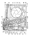
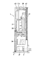
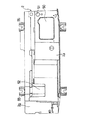
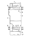
図1及び図2は、本発明のエンジン駆動熱ポンプ装置の一例としての空調装置における室外機ユニットとその内部構造を示している。これらの図に示すように、室外機ユニットは、動力部収納ケース1とその上方に配置される補助ケース10とからなる枠組みを有しており、この枠組みに室外機ユニットの構成部品を組み込んだ構造となっている。
【0013】
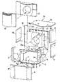
動力部収納ケース1は、熱ポンプ装置のコンプレッサとこれを駆動するエンジンとを含む動力部を収納、保持するもので、概略直方体の箱状とされ、当実施形態においては、このケース1の主要部をなすフレーム2が、少なくとも上下両面、一側面及び背面の4面の壁を一体に成形した鋳造品により構成されている。
【0014】
図3に示すように、上記フレーム2は、前面側の略全体に開口部3を有するとともに一方の側面(図示の例では正面から見て右側の側面)に部分的に開口部4を有し、上面部2a、底面部2b、背面部2c及び左側面部2dの各壁と、前面と右側面との間のコーナー部に設けられた支柱2eと、右側面の開口部4間に設けられた横桟部分2fとが、アルミ合金ダイカストで一体成形され、上記各壁で囲われた内部が、動力部を収納するエンジンルームとなっている。上記底面部2bはフレーム2の左側面部2dより外側に張出しており、この張出部分2gの上方に冷媒循環系の配管等を装備するための小室が形成されるようになっている。
【0015】
そして、上記フレーム2に対し、その前面側の開口部3を覆う正面パネル5、右側面の開口部4を覆う右側面パネル6、左側面部2dの外方において上記張出部分2gの上方の小室を囲う側面カバー7、背面側下部を覆う背面下部カバー8等がボルト等によって着脱可能に取付けられるようになっている。つまり、上記フレーム2、パネル5,6およびカバー7,8等で動力部収納ケース1が構成される。
【0016】
一方、上記補助ケース10の本体部分11は、略中央にファン配置用の空洞部12を有し、この空洞部12を囲うファンシュラウド11bと背面部11aとを一体に備え、合成樹脂により形成されている。当実施形態では、後述のエアクリーナ等が組込まれるケーシング部分11cが上記本体部分11の側部に一体に連成され、ファンシュラウド11bの一部が上記ケーシング部分11cの側壁を兼ねている。
【0017】
この補助ケース本体部分11に対し、上記空洞部12に対応する開口を有して本体部分11の前面側に配置される正面カバー13、上端部に配置される天井カバー14、右側面部に配置される右側面カバー15等がボルト等で着脱可能に取付けられて、補助ケース10が構成されるようになっている。また、上記正面カバー13に対して着脱可能なファンガード16が装備されている。
【0018】
上記補助ケース本体部分11の背面側には、室外熱交換器17が取付けられるようになっている。さらに、上記動力部収納ケース1のフレーム2と補助ケース本体部分11とにわたる背面側の左側部には背面上部カバー18がボルト等で取付けられ、また、補助ケース本体部分11の左側方部には、電装品を収納した電装品ボックス19(図1に示す)が組付けられるようになっている。
【0019】
そして、上記フレーム2上に補助ケース本体部分11が設置、固定されるとともに、これらに対してパネル5,6およびカバー7,8,13,14,15,18、室外熱交換器17、電装品ボックス19等が組付けられることにより、室外機ユニットの枠組みが構成されるようになっている。なお、図1及び2では、便宜上、両ケース1,10のカバーやパネルを取外した状態で内部を示している。
【0020】
上記動力部収納ケース1には、熱ポンプ装置のコンプレッサ21と、これを駆動するエンジン22とを含む動力部が収納されている。当実施形態において上記エンジン22は水冷ガスエンジンであり、このエンジン22のクランク軸22aとコンプレッサ21の回転軸とが駆動ベルト23を介して接続されるとともに、コンプレッサ21のハウジングがエンジン22のクランクケースに連結された状態で、これらエンジン22及びコンプレッサ21がフレーム2の底面部2b上に設置されている。
【0021】
具体的には、2つのマウントブラケット25が上記底面部2bの上面に所定の間隔でねじ締結されるとともに、これらマウントブラケット25の上方にそれぞれマウント24が配設され、上記コンプレッサ21及びエンジン22に取付けられた左右一対のブラケットと上記マウントブラケット25とが、上記マウント24を介して一体にボルトナットで連結、固定されることによりコンプレッサ21及びエンジン22が底面部2b上に支持されている。なお、マウントブラケット25は、後記ねじ穴59を介して底面部2bにねじ締結される(図6参照)。
【0022】
また、上記補助ケース10には、その上記空洞部12内に送風ファン30が配置されている。そして、エンジンの吸気系、燃料系、排気系、潤滑系及び冷却系と上記コンプレッサ21に連結される冷媒循環系の一部とが上記両ケース1,10にわたって配設されている。
【0023】
エンジンの吸気系は、エアクリーナ31と、このエアクリーナ31に外気を導入する吸気導入管32と、エアクリーナ31を通った空気をエンジンに導く吸気管33とを備えている。上記エアクリーナ31及び吸気導入管32は上記補助ケース10内に配置されている。また、吸気管33は、エアクリーナ31から下方に導出され、上記フレーム2の上面に設けられた窓穴4を通って動力部収納ケース1内に延び、エンジン22のヘッド部22b上側に設置されたミキサー34に接続されている。そして、このミキサー34で空気と燃料が混合されて、その混合気がエンジン22に供給されるようになっている。なお、エアクリーナ31の下方にはブローバイガス導出通路に接続されるオイルセパレータ35が配置されている。
【0024】
エンジンの燃料系は、上記ミキサー34に接続された燃料供給管36を備え、この燃料供給管36がフレーム2の左側面部を通り抜けて外部の燃料ガス供給源(図示せず)に接続されている。
【0025】
エンジンの排気系は、エンジン22の横に接続される排ガス熱交換器37から導出される排気管(図示せず)を備え、この排気管が上方へ延び、フレーム2の上面部に設けられた後記窓穴51を通って補助ケース10内に達し、エアクリーナ31の上方に配置された排気サイレンサ38に接続されている。
【0026】
エンジンの潤滑系は、オイルタンク39を備えている。このオイルタンク39は、エンジン22の側方に配置され、オイル流通管40を介してエンジン22のオイルパンに接続されている。
【0027】
また、エンジンの冷却系は、冷却水管(図示せず)を備え、この冷却水管が水ポンプ41から吐出される冷却水を、排ガス熱交換器37、エンジン22のウォータジャケット、ラジエータ42及び二重管熱交換器43等を介して再び水ポンプ41に導入するように構成されている。
【0028】
一方、上記コンプレッサ21に連結される冷媒循環系は、詳しく図示していないが、コンプレッサ21の吐出口に接続される吐出側冷媒管と、コンプレッサ21の吸入口に接続される吸入側冷媒管とを有し、これら各冷媒管が四方弁に接続されている。吐出側冷媒管にはオイルセパレータが介設され、吸入側冷媒管にはアキュムレータ44が介設されている。
【0029】
上記四方弁からは2本の冷媒管が導出され、一方側の冷媒管はパックドバルブ47及びストレーナ等を介してその先端が複数に分岐しており、各分岐管の先端にはフランジ45が設けられている。また、他方側の冷媒管は、二重管熱交換器43を経て室外熱交換器18に達し、さらに室外熱交換器18からフィルタドライヤ、サイトグラス、パックドバルブ48等を経てその先端が複数に分岐し、各分岐管に電子膨張弁49及びストレーナ等が介設されてその先端にフランジ46が設けられている。そして、図外の複数の室内熱交換器との接続用の配管が、上記各分岐管のフランジ45,46に着脱可能に接続されるようになっている。
【0030】
上記フレーム2のより詳細な構造を、図4〜図6を参照しつつ説明する。
【0031】
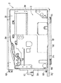
上記フレーム2の上面部2aの右側の部分には吸気管や排気管等を通す窓穴50,51が設けられている。上面部2aの左側の部分は右側の部分よりも低く形成され、かつ、その一部に、上記アキュムレータ44等での結露により生じる水を集めて背面側に導く凹部52が形成され、この凹部52の前端の壁面には冷媒循環系配管の取付部53が設けられている。
【0032】
上記フレーム2の底面部2bには、その下面側に、左右両端近傍に位置して前後方向に延びる一対の脚部55と、この一対の脚部55の間に配設された補強用のリブ56及び遮音用の突部57が一体に連設されるとともに、上面側に、上記マウントブラケット25の回り止め用の突条58及び取付け用のねじ穴59、オイルタンク39取付け用のねじ穴60等が設けられている。
【0033】
また、左側面部2dには、ワイヤーハーネス及び冷却水配管等を挿通させる配管類挿通部分(図示せず)が設けられるとともに、上記パックドバルブ47,48取付け用のブラケット61、正面パネル取付用ブラケット62等が一体に連成されている。
【0034】
ここで、上記フレーム2の特徴として、フレーム2には、底面部2bにのみユニットを構成する各種部品を取り付けるためのねじ穴が形成されており、底面部2b以外の各面にはねじ穴が一切設けられていない。つまり、上述のようにコンプレッサ21及びエンジン22を支持する上記マウントブラケット25やオイルタンク39等、高い支持剛性が要求される一部の部材についてのみ、これらがねじ穴59,60等を介して直接フレーム2にねじ締結され、それ以外の構成部材については、各部材が直接フレーム2にねじ締結されるのではなく、以下に説明するような手段で各部材がフレーム2に取り付けられるようになっている。
【0035】
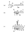
例えば、上記正面パネル5の取付けは、図7(a)に示すように、正面パネル取付用のブラケット62に貫通穴62aが形成されるとともに、このブラケット62にナットスプリング70が装着され、ナットスプリング70に対して正面パネル5がねじ締結されることにより達成されるようになっている。
【0036】
ナットスプリング70は、同図に示すように、U字型に折り曲げられた板ばね71の一方端側にナット部分72が設けられるとともに、他方端側にナット部分72に対応する切欠き部73が設けられた部材で、図7(b)に示すように、板ばね71の両端でブラケット62を挟むようにブラケット62に装着される。この際、ナット部分72が正面パネル5の取付け面の反対側に位置し、さらにナット部分72が貫通穴62aに対応するように装着される。
【0037】
そして、図7(c)に示すように、正面パネル5の取付け穴5a、上記切欠き部73及び貫通穴62aを介してボルト74がナットスプリング70のナット部分72に螺合挿入されることにより、正面パネル5がフレーム2に取り付けられるようになっている。
【0038】
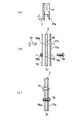
また、室外熱交換器17の取付けは、図8(a)に示すように、室外熱交換器17の両側にコ字状の支持プレート17aが固着されており、この支持プレート17aの下部がフレーム2に固定される。図8(b)に示すように、室外熱交換器17のフレーム2への固定は、例えば、エンジンルーム内に設けられる配管支持用のブラケット76と支持プレート17aとでフレーム2を挟み、支持プレート17aをブラケット76にねじ締結することにより達成される。
【0039】
具体的には、同図に示すように、フレーム2の背面部2cに上下2箇所の貫通穴75,76が形成され、この貫通穴75,76に対応する貫通穴17b,17cが支持プレート17aに形成されるとともに、貫通穴75,76に対応する貫通穴76a及びねじ穴76bがブラケット76に形成されている。なお、貫通穴17bは、後記樹脂クリップ77の突出し部分を逃げるため、貫通穴75,76aに対して大きく形成されている。そして、同図に示すように、ブラケット76、背面部2c及び支持プレート17aの各貫通穴76a、75、17bにわたってフレーム2の内側から樹脂クリップ77が挿着されることによりブラケット76がフレーム2に保持されるとともに、ボルト78が背面部2c及び支持プレート17aの各貫通穴17c、76を介してフレーム2の外側からブラケット76のねじ穴76bに螺合挿入されることにより、支持プレート17a及びブラケット76が一体にフレーム2に取り付けられるようになっている(図8(c))。
【0040】
なお、ここでは、正面パネル5及び室外熱交換器17について説明したが、フレーム2の底面部2b以外の面に取付けられるこれら以外の各ユニット構成部材も、基本的にはこれらと同様の手段でフレーム2に取付けられるか、あるいは、上記のようにして取付けられたブラケット76等を介してフレーム2に取り付けられている。また、図示を省略するが、例えば、背面下部カバー8は、その下部をフレーム2の上面に載置した後、室外熱交換器17をフレームに固定することにより、カバー8の上部をフレーム2の上面と室外熱交換器17の下端とで挟み込むようにしてフレーム2に組み付けられる。
【0041】
以上のような当実施形態の室外機ユニットによると、コンプレッサ21及びエンジン22を含む動力部が動力部収納ケース1に収納されるとともに、エンジンの燃料系、吸・排気系、冷却系、潤滑系等の構成部材や配管、及びコンプレッサ21に接続される冷媒潤滑系の構成部材や配管が、上記動力部収納ケース1とその上方に設置された補助ケース10とに合理的に配設される。
【0042】
そして、上記動力部収納ケース1の主要部をなすフレーム2は、上面部2a、底面部2b、背面部2c及び左側面部2dの4面の壁及び前面右側コーナーの支柱2eがアルミ合金ダイカストで一体成形されているため、フレーム2の剛性が高く、このフレーム2に、コンプレッサ21及びエンジン22等の動力部やフレーム2上の補助ケース15及び各種の室外機ユニット構成部材、配管が支持されることにより、室外機ユニット全体の強度が高められ、特に、エンジン22等がフレーム2により形成されるエンジンルーム内に配置されることで振動騒音が効果的に低減される。
【0043】
しかも、上記フレーム2については、上述のようにエンジン22等を支持するマウントブラケット25やオイルタンク39等、一部のユニット構成部材だけがフレーム2の底面部2bに直接ねじ締結で取り付けられる、つまり、底面部2bにのみ取付け用のねじ穴が設けられるようになっているため、フレーム2の製造の手間が大幅に削減されるという特徴がある。すなわち、アルミ合金ダイカストで一体成形されるフレームにねじ穴を形成する場合、鋳造時に下穴を形成しておき、成形後、二次加工としてタップ加工を行う必要がある。そのため、フレームの各面にねじ穴を設けようとすると、二次加工時にフレームの姿勢を順次変えながら各面に加工を施す必要があるが、この場合、フレーム2は比較的大きくまた重量を有するため多大な手間と労力が必要となる。しかし、上記実施形態のフレーム2では、底面部2bにのみねじ穴が設けられているため、フレーム2の製造時には、鋳造後のフレーム2に対して、その一面にのみタップ加工を施せばよく、フレームの全面にねじ穴を設けるものに比べると二次加工の手間及び労力を大幅に軽減することができる。
【0044】
なお、上記実施形態では、二次加工の一例として、鋳造により成形された下穴にねじを切るタップ加工を例に説明したが、例えば、二次加工としては、フレーム成形後のゲート部処理も考えられる。従って、金型のゲート部をフレーム2の底面部2bに対応して設けるようにし、上記タップ加工と併せてゲート部の処理を行うようにするようにしてもよい。このようにすれば二次加工の手間を軽減する上でより好ましい。
【0045】
【発明の効果】
以上説明したように、本発明のエンジン駆動熱ポンプ装置の室外機ユニットは、動力部収納ケースに関し、ケースの主要部をなすフレームを、少なくとも上下両面、一側面及び背面の4面の壁を有する一体成形の鋳造品により構成するようにしたので、板金により別体に形成した壁や支柱を溶接やボルト止めで結合していくものと比較すると、フレームの剛性を充分に高めることができる。しかも、鋳造品の一面にのみねじ穴を要する部分を集約するようにしたので、下穴にタップ加工を施すという二次加工時には、フレームの一面に対してのみ加工を施せばよく、そのため、二次加工に要する手間や労力を大幅に軽減することができる。そして、この動力部収納ケースのフレームをベースとして補助ケース、室外熱交換器、補助ケース内のファンやその他室外機ユニットに具備されるべき各種部材、配管等が組付けられ、この場合に上記フレームが鋳造品からなっていて剛性が高いため、室外機ユニット全体の堅牢性が確保され、また振動騒音が効果的に抑えられる。
【図面の簡単な説明】
【図1】 本発明のエンジン駆動熱ポンプ装置の室外機ユニットの一例を示す正面図である。
【図2】 上記室外機ユニットの側面図である。
【図3】 上記室外機ユニットに適用される動力部収納ケース及び補助ケースの分解斜視図である。
【図4】 上記フレームの正面図である。
【図5】 上記フレームの平面図である。
【図6】 上記フレームの水平断面図である。
【図7】 (a)〜(c)は、フレームへの正面パネルの取付け構造を説明する図で、(a)はフレームのブラケットと、これに装着されるナットスプリングを示す断面図、(b)はブラケットにナットスプリングを装着した状態を示す断面図、(c)はナットスプリングに取付けられる正面パネルを示す断面図である。
【図8】 (a)〜(c)は、フレームへの室外熱交換器の取付け構造を説明する図で、(a)はフレームに取付けられた室外熱交換器を示す断面図、(b)は室外熱交換器の取付け構造を説明する要部断面分解図、(c)はフレームに室外熱交換器が取付けられた状態を示す図(a)のI−I断面図である。
【符号の説明】
1 動力部収納ケース
2 フレーム
2a 上面部
2b 底面部
2c 背面部
2d 左側面部
2e 支柱
2f 横桟部分
2g 張出部分
15 補助ケース
21 コンプレッサ
22 エンジン[0001]
BACKGROUND OF THE INVENTION
The present invention relates to an outdoor unit in a heat pump device such as an engine-driven air conditioner.
[0002]
[Prior art]
Conventionally, an engine-driven heat pump device in which a compressor is driven by an engine is generally known in an air conditioner or the like. When applied to an air conditioner, the engine-driven heat pump device includes an indoor unit unit disposed in one or more rooms and an outdoor unit connected to the indoor unit.
[0003]
The outdoor unit includes a power unit including a compressor and an engine, an engine fuel system, an intake / exhaust system, a cooling system and a lubrication system, and a part of a refrigerant circulation system connected to the compressor. (See, for example, Japanese Patent Laid-Open No. 61-162861).
[0004]
[Problems to be solved by the invention]
In this type of outdoor unit, the case needs to house a heavy engine and the like, and must have high rigidity because it is necessary to suppress vibration noise, but it is preferable that the case is easy to manufacture.
[0005]
Therefore, the applicant of the present application considers that the upper and lower surfaces and side surfaces of the case are molded by casting, thereby increasing the rigidity of the case, while greatly reducing the manufacturing process.
[0006]
However, since the case integrally molded by casting has a considerable weight and volume, when performing so-called secondary processing such as tapping, the case is moved or the case is suitable for work. Therefore, it is considered to be troublesome and requires a lot of labor, and therefore it is desirable to effectively reduce the labor and labor required for such secondary processing.
[0007]
The present invention has been made in view of the above circumstances, while integrally molded by casting case, providing a chamber outside unit of the engine-driven heat pump apparatus capable of effectively reducing the labor and labor required for secondary next machining The purpose is to do.
[0008]
[Means for Solving the Problems]
The invention according to claim 1 is an outdoor unit of an engine-driven heat pump device in which a power unit including a compressor of a heat pump device and an engine that drives the compressor is housed in a power unit housing case, the power unit housing case And a screw hole for attaching various unit constituent members only to one surface of the cast product. Auxiliary case that is formed by consolidating the above-mentioned power parts that require support rigidity and is screwed to the frame through the screw holes, and a blower fan is incorporated on the frame of the power part storage case And an outdoor heat exchanger arranged on the back side of the engine, and are connected to the engine fuel system, intake / exhaust system, cooling system, lubrication system and the compressor. A part of the refrigerant circulatory system are those in which is disposed over the both case (claim 1).
[0009]
According to this arrangement relates to a power unit housing case, its production by a frame which forms the main part of its is formed integrally with the casting is simplified, also sufficient by the wall of the four sides is integrally cast The rigidity is increased. Moreover, since the only provided for one side of the screw holes case, since the secondary processing that performs tapping on the pilot hole may be allowed implementation of to said one surface, Ya labor required for secondary processing Labor is greatly reduced . Then, based on the frame of the power unit storage case, an auxiliary case, an outdoor heat exchanger, a fan in the auxiliary case and other various members, pipes, etc. to be provided in the outdoor unit are assembled. Since it is made of a cast product and has high rigidity, the robustness of the entire outdoor unit is ensured, and vibration noise is effectively suppressed.
[0010]
The screw holes may be concentrated on either side, but for heavy objects such as engines, it is structurally advantageous to screw them to the bottom rather than the side of the frame. In order to give priority to securing the rigidity, it is effective to collect screw holes on the bottom surface of the case (claim 2).
[0011]
DETAILED DESCRIPTION OF THE INVENTION
Embodiments of the present invention will be described with reference to the drawings.
[0012]
1 and 2 show an outdoor unit and its internal structure in an air conditioner as an example of the engine-driven heat pump device of the present invention. As shown in these drawings, the outdoor unit has a frame made up of a power unit storage case 1 and an
[0013]
The power unit storage case 1 stores and holds a power unit including a compressor of a heat pump device and an engine that drives the compressor, and is formed in a substantially rectangular parallelepiped box shape. The
[0014]
As shown in FIG. 3, the
[0015]
A
[0016]
On the other hand, the main body portion 11 of the
[0017]
With respect to this auxiliary case main body part 11, it has an opening corresponding to the
[0018]
An
[0019]
The auxiliary case body 11 is installed and fixed on the
[0020]
The power unit storage case 1 stores a power unit including a
[0021]
Specifically, two
[0022]
The
[0023]
The intake system of the engine includes an
[0024]
The engine fuel system includes a
[0025]
The engine exhaust system includes an exhaust pipe (not shown) led out from an exhaust
[0026]
The engine lubrication system includes an
[0027]
The engine cooling system includes a cooling water pipe (not shown). The cooling water pipe discharges the cooling water discharged from the water pump 41 into the exhaust
[0028]
On the other hand, the refrigerant circulation system connected to the
[0029]
Two refrigerant pipes are led out from the four-way valve, and one end of the refrigerant pipe branches into a plurality of parts through a packed
[0030]
A more detailed structure of the
[0031]
Window holes 50 and 51 through which intake pipes, exhaust pipes and the like are passed are provided on the right side of the
[0032]
The
[0033]
The
[0034]
Here, as a feature of the
[0035]
For example, as shown in FIG. 7A, the
[0036]
As shown in the figure, the
[0037]
Then, as shown in FIG. 7C, the
[0038]
As shown in FIG. 8A, the
[0039]
Specifically, as shown in the drawing, two through
[0040]
In addition, although the
[0041]
According to the outdoor unit of the present embodiment as described above, the power unit including the
[0042]
The
[0043]
Moreover, with respect to the
[0044]
In the above embodiment, as an example of the secondary processing, the tap processing for cutting the screw into the prepared hole formed by casting has been described as an example. However, as the secondary processing, for example, the gate processing after frame forming is also performed. Conceivable. Therefore, the gate portion of the mold may be provided corresponding to the
[0045]
【The invention's effect】
As described above, the outdoor unit of the engine-driven heat pump device according to the present invention relates to a power unit storage case, and has a frame that forms a main part of the case having at least four upper and lower surfaces, one side surface, and four rear walls. Since it is configured by an integrally molded casting, the rigidity of the frame can be sufficiently increased as compared with a structure in which a wall or a column formed separately by sheet metal is joined by welding or bolting. In addition, since the parts that require screw holes are gathered only on one surface of the cast product, it is only necessary to perform processing on one surface of the frame during the secondary processing of tapping the pilot hole. The labor and labor required for the next processing can be greatly reduced. Then, based on the frame of the power unit storage case, an auxiliary case, an outdoor heat exchanger, a fan in the auxiliary case and other various members, pipes, etc. to be provided in the outdoor unit are assembled. Since it is made of a cast product and has high rigidity, the robustness of the entire outdoor unit is ensured, and vibration noise is effectively suppressed.
[Brief description of the drawings]
FIG. 1 is a front view showing an example of an outdoor unit of an engine-driven heat pump device according to the present invention.
FIG. 2 is a side view of the outdoor unit.
FIG. 3 is an exploded perspective view of a power unit storage case and an auxiliary case applied to the outdoor unit.
FIG. 4 is a front view of the frame.
FIG. 5 is a plan view of the frame.
FIG. 6 is a horizontal sectional view of the frame.
FIGS. 7A to 7C are views for explaining a structure for attaching a front panel to a frame. FIG. 7A is a sectional view showing a bracket of the frame and a nut spring attached to the frame. ) Is a cross-sectional view showing a state in which a nut spring is mounted on the bracket, and (c) is a cross-sectional view showing a front panel attached to the nut spring.
FIGS. 8A to 8C are views for explaining a structure for attaching an outdoor heat exchanger to the frame, FIG. 8A is a cross-sectional view showing the outdoor heat exchanger attached to the frame, and FIG. FIG. 2 is an exploded cross-sectional view of a main part for explaining the mounting structure of the outdoor heat exchanger, and FIG. 2C is a cross-sectional view taken along the line II of FIG. 1A showing a state where the outdoor heat exchanger is mounted on the frame.
[Explanation of symbols]
DESCRIPTION OF SYMBOLS 1 Power
Claims (2)
上記動力部収納ケースの主要部をなすフレームを、少なくとも上下両面、一側面及び背面の4面の壁を有する一体成形の鋳造品により構成するとともに、この鋳造品の一面にのみ各種ユニット構成部材を取り付けるためのねじ穴を集約して形成し、
上記動力部のうち支持剛性が要求されるものを上記ねじ穴を介してフレームにねじ締結するとともに、上記動力部収納ケースのフレーム上に、送風ファンを組み込んだ補助ケースと、その背面側に配置された室外熱交換器とを支持させ、エンジンの燃料系、吸・排気系、冷却系及び潤滑系と上記コンプレッサに連結される冷媒循環系の一部とを上記両ケースにわたって配設したことを特徴とするエンジン駆動熱ポンプ装置の室外機ユニット。A chamber outside unit of the engine-driven heat pump unit housed in the power unit housing case the power unit including a compressor and an engine for driving the heat pump device,
The frame constituting the main part of the power unit storage case is constituted by an integrally molded cast product having at least four upper and lower surfaces, one side surface, and the back wall, and various unit constituent members are provided only on one surface of the cast product. Collecting and forming screw holes for mounting,
The power unit that requires support rigidity is screwed to the frame through the screw hole, and the auxiliary case in which the blower fan is incorporated on the frame of the power unit storage case and the rear side thereof And the engine fuel system, intake / exhaust system, cooling system and lubrication system, and a part of the refrigerant circulation system connected to the compressor are disposed over both cases. An outdoor unit for an engine-driven heat pump device.
Priority Applications (1)
| Application Number | Priority Date | Filing Date | Title |
|---|---|---|---|
| JP04574397A JP3649844B2 (en) | 1997-02-28 | 1997-02-28 | Outdoor unit |
Applications Claiming Priority (1)
| Application Number | Priority Date | Filing Date | Title |
|---|---|---|---|
| JP04574397A JP3649844B2 (en) | 1997-02-28 | 1997-02-28 | Outdoor unit |
Publications (2)
| Publication Number | Publication Date |
|---|---|
| JPH10238820A JPH10238820A (en) | 1998-09-08 |
| JP3649844B2 true JP3649844B2 (en) | 2005-05-18 |
Family
ID=12727809
Family Applications (1)
| Application Number | Title | Priority Date | Filing Date |
|---|---|---|---|
| JP04574397A Expired - Fee Related JP3649844B2 (en) | 1997-02-28 | 1997-02-28 | Outdoor unit |
Country Status (1)
| Country | Link |
|---|---|
| JP (1) | JP3649844B2 (en) |
-
1997
- 1997-02-28 JP JP04574397A patent/JP3649844B2/en not_active Expired - Fee Related
Also Published As
| Publication number | Publication date |
|---|---|
| JPH10238820A (en) | 1998-09-08 |
Similar Documents
| Publication | Publication Date | Title |
|---|---|---|
| US6758169B2 (en) | Engine generator | |
| EP1296040B1 (en) | Engine generator | |
| US20160233739A1 (en) | Electrical generator heat management system | |
| JP3122715B2 (en) | Indoor unit of air conditioner | |
| JP2000071181A (en) | Drive unit for manually operated working machine | |
| JP3649844B2 (en) | Outdoor unit | |
| JP3639403B2 (en) | Outdoor unit of engine-driven heat pump device | |
| JPH11294280A (en) | Engine intake system | |
| JP3728043B2 (en) | Outdoor unit of engine-driven heat pump device | |
| JP3619630B2 (en) | Outdoor unit of engine-driven heat pump device | |
| JP2545597B2 (en) | Soundproof engine work machine | |
| JPH10238821A (en) | Outdoor unit of engine driven heat pump device | |
| JP3754163B2 (en) | Water pump housing structure in outdoor unit of water cooling engine drive heat pump device | |
| JP3723313B2 (en) | Ventilation structure in outdoor unit of engine driven heat pump | |
| JP2945914B2 (en) | Outdoor unit of engine driven heat pump | |
| JP3653365B2 (en) | Outdoor unit of engine-driven heat pump device | |
| JPH10238818A (en) | Outdoor unit of engine driven heat pump device | |
| JP2001116296A (en) | Outdoor air conditioning unit for engine driven air conditioners | |
| JP2001141331A (en) | Engine room structure of engine driven heat transfer device | |
| JP3685579B2 (en) | Outdoor unit of engine-driven heat pump device | |
| JPH10238823A (en) | Outdoor unit of engine driven heat pump device | |
| CA2918574C (en) | Electrical generator heat management system | |
| JPH0769092B2 (en) | Engine heat pump | |
| JP3212409B2 (en) | Outdoor unit of air conditioner | |
| KR200168621Y1 (en) | Assembly construction of fan shroud in radiator fan |
Legal Events
| Date | Code | Title | Description |
|---|---|---|---|
| A977 | Report on retrieval |
Free format text: JAPANESE INTERMEDIATE CODE: A971007 Effective date: 20040924 |
|
| A131 | Notification of reasons for refusal |
Free format text: JAPANESE INTERMEDIATE CODE: A131 Effective date: 20041109 |
|
| A521 | Written amendment |
Free format text: JAPANESE INTERMEDIATE CODE: A523 Effective date: 20050105 |
|
| TRDD | Decision of grant or rejection written | ||
| A01 | Written decision to grant a patent or to grant a registration (utility model) |
Free format text: JAPANESE INTERMEDIATE CODE: A01 Effective date: 20050201 |
|
| A61 | First payment of annual fees (during grant procedure) |
Free format text: JAPANESE INTERMEDIATE CODE: A61 Effective date: 20050216 |
|
| FPAY | Renewal fee payment (event date is renewal date of database) |
Free format text: PAYMENT UNTIL: 20090225 Year of fee payment: 4 |
|
| LAPS | Cancellation because of no payment of annual fees |