JP3649842B2 - PBX network - Google Patents
PBX network Download PDFInfo
- Publication number
- JP3649842B2 JP3649842B2 JP04233197A JP4233197A JP3649842B2 JP 3649842 B2 JP3649842 B2 JP 3649842B2 JP 04233197 A JP04233197 A JP 04233197A JP 4233197 A JP4233197 A JP 4233197A JP 3649842 B2 JP3649842 B2 JP 3649842B2
- Authority
- JP
- Japan
- Prior art keywords
- pbx
- telephone
- call
- information element
- extension
- Prior art date
- Legal status (The legal status is an assumption and is not a legal conclusion. Google has not performed a legal analysis and makes no representation as to the accuracy of the status listed.)
- Expired - Fee Related
Links
Images


Classifications
-
- H—ELECTRICITY
- H04—ELECTRIC COMMUNICATION TECHNIQUE
- H04Q—SELECTING
- H04Q3/00—Selecting arrangements
- H04Q3/58—Arrangements providing connection between main exchange and sub-exchange or satellite
- H04Q3/62—Arrangements providing connection between main exchange and sub-exchange or satellite for connecting to private branch exchanges
-
- H—ELECTRICITY
- H04—ELECTRIC COMMUNICATION TECHNIQUE
- H04M—TELEPHONIC COMMUNICATION
- H04M1/00—Substation equipment, e.g. for use by subscribers
- H04M1/57—Arrangements for indicating or recording the number of the calling subscriber at the called subscriber's set
-
- H—ELECTRICITY
- H04—ELECTRIC COMMUNICATION TECHNIQUE
- H04Q—SELECTING
- H04Q2213/00—Indexing scheme relating to selecting arrangements in general and for multiplex systems
- H04Q2213/13091—CLI, identification of calling line
-
- H—ELECTRICITY
- H04—ELECTRIC COMMUNICATION TECHNIQUE
- H04Q—SELECTING
- H04Q2213/00—Indexing scheme relating to selecting arrangements in general and for multiplex systems
- H04Q2213/13097—Numbering, addressing
-
- H—ELECTRICITY
- H04—ELECTRIC COMMUNICATION TECHNIQUE
- H04Q—SELECTING
- H04Q2213/00—Indexing scheme relating to selecting arrangements in general and for multiplex systems
- H04Q2213/13102—Common translator
-
- H—ELECTRICITY
- H04—ELECTRIC COMMUNICATION TECHNIQUE
- H04Q—SELECTING
- H04Q2213/00—Indexing scheme relating to selecting arrangements in general and for multiplex systems
- H04Q2213/13176—Common channel signaling, CCS7
-
- H—ELECTRICITY
- H04—ELECTRIC COMMUNICATION TECHNIQUE
- H04Q—SELECTING
- H04Q2213/00—Indexing scheme relating to selecting arrangements in general and for multiplex systems
- H04Q2213/13204—Protocols
-
- H—ELECTRICITY
- H04—ELECTRIC COMMUNICATION TECHNIQUE
- H04Q—SELECTING
- H04Q2213/00—Indexing scheme relating to selecting arrangements in general and for multiplex systems
- H04Q2213/13205—Primary rate access, PRI
-
- H—ELECTRICITY
- H04—ELECTRIC COMMUNICATION TECHNIQUE
- H04Q—SELECTING
- H04Q2213/00—Indexing scheme relating to selecting arrangements in general and for multiplex systems
- H04Q2213/13209—ISDN
-
- H—ELECTRICITY
- H04—ELECTRIC COMMUNICATION TECHNIQUE
- H04Q—SELECTING
- H04Q2213/00—Indexing scheme relating to selecting arrangements in general and for multiplex systems
- H04Q2213/13216—Code signals, frame structure
-
- H—ELECTRICITY
- H04—ELECTRIC COMMUNICATION TECHNIQUE
- H04Q—SELECTING
- H04Q2213/00—Indexing scheme relating to selecting arrangements in general and for multiplex systems
- H04Q2213/1322—PBX
-
- H—ELECTRICITY
- H04—ELECTRIC COMMUNICATION TECHNIQUE
- H04Q—SELECTING
- H04Q2213/00—Indexing scheme relating to selecting arrangements in general and for multiplex systems
- H04Q2213/13286—Direct in-dialling in PBX, DDI
-
- H—ELECTRICITY
- H04—ELECTRIC COMMUNICATION TECHNIQUE
- H04Q—SELECTING
- H04Q2213/00—Indexing scheme relating to selecting arrangements in general and for multiplex systems
- H04Q2213/13395—Permanent channel, leased line
Landscapes
- Physics & Mathematics (AREA)
- Astronomy & Astrophysics (AREA)
- General Physics & Mathematics (AREA)
- Engineering & Computer Science (AREA)
- Computer Networks & Wireless Communication (AREA)
- Sub-Exchange Stations And Push- Button Telephones (AREA)
- Telephonic Communication Services (AREA)
Description
【0001】
【発明の属する技術分野】
本発明はPBXネットワーク網に関し、公衆ISDN網に接続された複数のPBXで構成したPBXネットワーク網に関する。
【0002】
【従来の技術】
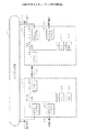
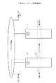
図25はPBXネットワーク網の構成図を示す。同図中、PBX(構内交換機)10,12夫々はISDN(サービス総合ディジタルネットワーク)公衆網14に接続されており、内線電話相互、及び内線電話18,20とISDN公衆網14に接続された加入者電話22,24とをつなぐ。また、PBX10,12はISDN中継線16で相互に接続されてPBXネットワーク網を構成している。
【0003】
従来のPBXネットワーク網ではISDN中継線16で接続された対向PBXへのメッセージ中にPBXの番号(例えばPBX10は「700」,PBX12は「710」等)、及び内線の発ID(例えば内線電話18は「A」,内線電話20は「B」等)を格納して通知している。
【0004】
【発明が解決しようとする課題】
従来のPBXネットワーク網ではISDN公衆網14の加入者電話22からISDN公衆網14,PBX10,ISDN中継線16,PBX12を経由して内線電話20に電話をかけることができる。しかし、この場合、PBX10からPBX12へのメッセージ中ではPBX10の番号「700」と、ISDN公衆網14の識別符号とが通知され、加入者電話22へ電話をかけるための発ID(例えば「X」)を通知できず、内線電話20から加入者電話22に折り返し電話をかける場合に不便であった。
【0005】
また、PBX10の内線電話18からISDN中継線16,PBX12,ISDN公衆網14を経由して加入者電話24に電話をかけることができる。しかし、この場合、PBX10からPBX12へのメッセージ中ではPBX10の番号「700」と内線電話18の発ID「A」とが通知されるものの、ISDN公衆網14から加入者電話24へのメッセージ中ではPBX12に対する発信IDが通知される。このため、加入者電話24からPBX10の内線電話18に折り返し発信する場合に不便であるという問題があった。
【0006】
本発明は、上記の点に鑑みなされたもので、PBXネットワークのISDN中継線を経由した通話で、発信した加入者電話の電話番号や内線電話のダイヤルイン番号を着信した電話に通知でき、上記電話番号の表示や折り返し発信が可能で利便性が向上するPBXネットワーク網を提供することを目的とする。
【0007】
【課題を解決するための手段】
請求項1に記載の発明は、ISDN公衆網に接続された複数の構内交換機をISDN中継線で接続したPBXネットワーク網において、
前記構内交換機は、
前記ISDN公衆網の加入者電話から発信されたとき前記ISDN中継線のプロトコルの呼設定メッセージに発信した加入者電話の電話番号である公衆発ID情報要素を付加サービス情報要素として追加する手段と、
内線電話の内線番号をダイヤルイン番号に変換する内線ダイヤルイン番号変換テーブルと、
内線電話から発信されたとき前記ISDN中継線のプロトコルの呼設定メッセージに、発信した内線電話のダイヤルイン番号を付加サービス情報要素として追加する
する手段を有する。
【0008】
このため、ISDN公衆網の加入者電話からPBXネットワーク網を経由して構内交換機の内線電話に発信した場合に、着信した内線電話に加入者電話の電話番号を通知でき、この着信した内線電話で発信元の電話番号の表示や折り返し発信が可能となり、内線電話からPBXネットワーク網を経由して構内交換機の内線電話に発信した場合に、着信した内線電話に発信した内線電話のダイヤルイン番号を通知でき、この着信した内線電話で発信元のダイヤルイン番号の表示や折り返し発信が可能となる。
請求項2に記載の発明は、請求項1記載のPBXネットワーク網において、
前記構内交換機は、
前記ISDN中継線から呼設定プロトコルの通知を受けたとき前記付加サービス情報要素としての公衆発ID情報要素またはダイヤルイン番号をISDN公衆網のプロトコルの呼設定メッセージの発ID情報要素に設定して前記ISDN公衆網の加入者電話に発信する手段を有する。
【0009】
このため、ISDN公衆網の加入者電話からPBXネットワーク網を経由してISDN公衆網の加入者電話に発信した場合に、着信した加入者電話に発信元の加入者電話の電話番号を通知でき、この着信した加入者電話で発信元の電話番号の表示や折り返し発信が可能となり、内線電話からPBXネットワーク網を経由してISDN公衆網の加入者電話に発信した場合に、着信した加入者電話に発信した内線電話のダイヤルイン番号を通知でき、この着信した加入者電話で発信元のダイヤルイン番号の表示や折り返し発信が可能となる。
請求項3に記載の発明は、請求項1又は2記載のPBXネットワーク網において、
前記構内交換機は、
前記ISDN公衆網の加入者電話から発信されたとき自交換機の内線電話に着信して通信後、転送操作により前記ISDN中継線を通してPBXの内線電話又はISDN公衆網の加入者電話に発信する手段を有する。
【0010】
このため、ISDN公衆網の加入者電話からPBXネットワークの構内交換機の内線電話に着信して通信した後、PBXネットワーク網を経由して内線電話又はISDN公衆網の加入者電話に転送した場合に、転送された内線電話、又は加入者電話に発信元の加入者電話の電話番号を通知でき、転送された電話で発信元の電話番号の表示や折り返し発信が可能となる。
【0013】
請求項4に記載の発明は、請求項2記載のPBXネットワーク網において、
前記構内交換機は、
前記ISDN中継線から呼設定プロトコルの通知を受けたとき自交換機の内線電話に着信して通信後、転送操作により前記ISDN公衆網の加入者電話に発信する手段を有する。
【0014】
このため、内線電話からPBXネットワーク網を経由して内線電話に発信した後、ISDN公衆網の加入者電話に転送した場合に、転送された加入者電話に発信した内線電話のダイヤルイン番号を通知でき、この転送された加入者電話で発信元のダイヤルイン番号の表示や折り返し発信が可能となる。
【0015】
【発明の実施の形態】
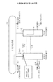
図2は本発明のPBXネットワーク網の一実施例の構成図を示す。同図中、PBX30,32夫々はISDN公衆網34に接続されており、内線電話相互、及び内線電話38,40とISDN公衆網34に接続された加入者電話とをつなぐ。また、PBX30,32はISDN中継線36で相互に接続されてPBXネットワーク網を構成している。
【0016】
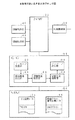
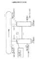
図1はPBX30,32の一実施例のブロック図を示す。同図中、回線制御部46はBTK(BRI局線)トランクカード、及びPTK(PRI局線)トランクカード、よりなりISDN公衆網34との回線接続の制御を行う。回線制御部48はDTLC(ディジタル内線カード)及びBLC(BRI内線カード)よりなり内線電話38等との回線接続を制御する。回線制御部50はITK(ISDN中継線トランク)よりなり、ISDN中継線との回線接続を制御する。NW(ネットワーク部)52はCC(中央処理装置)54の制御に従って、回線制御部46,48,50夫々の回線を接続する。
【0017】
CC54は上記の回線接続制御を行う他に、メッセージ変換制御を行っている。このメッセージ変換制御はCC54内のメッセージ受信部60,情報要素抽出部61,情報要素制御部62,情報要素編集部63,メッセージ送信部64によって実行される。
MM(メインメモリ)56にはCC54が回線接続制御を行うときに使用するDIL変換テーブル65等の回線接続情報の他に、メッセージ変換制御に用いる内線ダイヤルイン番号変換テーブル66が設けられている。
【0018】
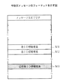
本発明でISDN中継線36で使用する呼設定(SETUP)メッセージのフォーマットを図3,図4夫々に示す。図3では呼設定メッセージのコードセット0には発信した電話を識別するための発ID情報要素M1と、着信する電話を識別するための着ID情報要素M2とが設定される。また、追加のコードセットであるコードセット7には付加サービス情報要素としてISDN公衆網34で発信した電話を識別するための公衆発ID情報要素M3が設定される。
【0019】
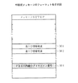
また、図4中、呼設定メッセージのコードセット0には発ID情報要素M1と、着ID情報要素M2とが設定され、また、コードセット7には付加サービス情報要素としてPBX30,32の内線電話38,40についてのダイヤルイン番号M4が設定される。
メッセージ受信部60は回線制御部46又は50からのメッセージを受信する。このメッセージは情報要素抽出部61に供給され、呼設定メッセージでは図3,図4夫々に示す発ID情報要素M1、着ID情報要素M2、公衆発ID情報要素M3、ダイヤルイン番号M4が抽出される。これらの抽出された情報要素は情報要素制御部62に供給される。
【0020】
情報要素制御部62は回線制御部46,50からの呼設定メッセージの着ID情報要素M2でDIL変換テーブル65を検索してPBXネットワーク網のPBX番号及び内線番号に変換する。また、回線制御部48を通して内線電話より発信があれば、内線ダイヤルイン番号変換テーブル66を検索して、その内線電話のダイヤルイン番号を得る。情報要素編集部63はDIL変換テーブル65の検索で得られたPBX番号及び内線番号を呼設定メッセージの着ID情報要素M2に設定し、また抽出した発ID情報要素M1を呼設定メッセージの公衆発ID情報要素M3に設定し、抽出した公衆発ID情報要素M3を呼設定メッセージの発ID情報要素M1に設定する。また、内線ダイヤルイン番号変換テーブル66の検索で得られた内線番号を呼設定メッセージのダイヤルイン番号M4に設定し、抽出されたダイヤルイン番号M4を呼設定メッセージの発ID情報要素M1に設定する等の編集を行う。メッセージ送信部64は編集されたメッセージを回線制御部46又は50に送出する。
【0021】
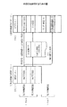
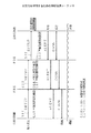
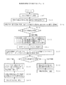
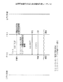
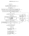
図5は加入者電話42からISDN公衆網34,PBX30,ISDN中継線36,PBX32を経由して電話をかける場合のフローチャートを示す。この場合、PBX32の内線電話40にかける場合と、PBX32から更にISDN公衆網34の加入者電話44にかける場合がある。
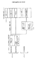
まず、図6に破線で示すように内線電話40にかける場合について説明する。図7はこの場合の情報伝達シーケンスであり、そのステップは図5と対応している。図8はこの場合の呼設定メッセージを説明するための図である。図5のステップS10でISDN公衆網34の加入者電話42からPBX30に発信する。これによってISDN公衆網34からPBX30に図8にSM1で示す設定メッセージが供給される。設定(SETUP)メッセージSM1ではコードセット0の発ID情報要素として「044777XXXX」がセットされ、着ID情報要素として「044777ABCD」がセットされている。
【0022】
ステップS12でPBX30に着信すると、PBX30はステップS14で呼設定メッセージSM1のコードセット0から発ID情報要素及び着ID情報要素を抽出する。次にステップS16で抽出した着ID情報要素を用いてDIL変換テーブル65を参照してPBX32経由の着ID情報要素に変換する。ここでは、「044777ABCD」が「710+ZZZZ」に変換される。次にステップS18で着ID情報から接続先を判別するが、この場合は接続先がISDN中継線36であるのでステップS20に進む。ステップS20ではISDN中継線36の呼設定メッセージを設定する。ここでは図3に示すコードセット0の発ID情報要素M1に伝送先のPBX32のPBX番号「700」と、PBX30のISDN公衆網34の接続回線を示す局発特番「0」と、抽出した発ID情報要素「044777XXXX」とを設定する。また、コードセット0の着ID情報要素SM2に、ステップS16で変換したPBX32経由の着ID情報要素「710+ZZZZ」を設定し、コードセット7の公衆発ID情報要素M3にステップS14で抽出した発ID情報要素「044777XXXX」を設定する。次のステップS22で上記のようにして設定した図8にSM2で示す呼設定メッセージを用いてPBX32に発信する。
【0023】
次にPBX32はステップS24でISDN中継線36の呼設定メッセージのコードセット7の公衆発ID情報要素から加入者電話42の発ID情報要素「044777XXXX」を抽出し、またコードセット0の着ID情報要素を抽出する。次にステップS26で抽出した着ID情報要素から接続先を判別する。この場合接続先はPBX32の内線電話40であるのでステップS28に進む。ステップS28ではステップS24で抽出した発信元の加入者電話42の発ID情報要素を着信時に内線電話40に設定し、内線電話40に加入者電話42の発ID情報要素「044777XXXX」が表示され、折り返し発信が可能となる。この後、ステップS30で内線電話40の応答により加入者電話42,内線電話40間の通話が行われる。
【0024】
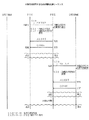
次に、図9に破線で示すように加入者電話44にかける場合について説明する。図10はこの場合の情報伝達シーケンスであり、そのステップは図5と対応している。図11はこの場合の呼設定メッセージを説明するための図である。図5のステップS10でISDN公衆網34の加入者電話42からPBX30に発信する。これによってISDN公衆網34からPBX30に図11にSM3で示す設定メッセージが供給される。設定(SETUP)メッセージSM3ではコードセット0の発ID情報要素として「044777XXXX」がセットされ、着ID情報要素として「044777****」がセットされている。
【0025】
ステップS12でPBX30に着信すると、PBX30はステップS14で呼設定メッセージSM1のコードセット0から発ID情報要素及び着ID情報要素を抽出する。次にステップS16で抽出した着ID情報要素を用いてDIL変換テーブル65を参照してPBX32経由の着ID情報要素に変換する。ここでは、「044777****」が「710+0+06949YYYY」に変換される。次にステップS18で着ID情報から接続先を判別するが、この場合は接続先がISDN中継線36であるのでステップS20に進む。ステップS20ではISDN中継線36の呼設定メッセージを設定する。ここでは図3に示すコードセット0の発ID情報要素M1に伝送先のPBX32のPBX番号「700」と、PBX30のISDN公衆網34の接続回線を示す局発特番「0」と、抽出した発ID情報要素「044777XXXX」とを設定する。また、コードセット0の着ID情報要素SM4に、ステップS16で変換したPBX32経由の着ID情報要素「710+0+06949YYYY」を設定し、コードセット7の公衆発ID情報要素M3にステップS14で抽出した発ID情報要素「044777XXXX」を設定する。次のステップS22で上記のようにして設定した図11にSM4で示す呼設定メッセージを用いてPBX32に発信する。
【0026】
次にPBX32はステップS24でISDN中継線36の呼設定メッセージのコードセット7の公衆発ID情報要素から加入者電話42の発ID情報要素「044777XXXX」を抽出し、またコードセット0の着ID情報要素を抽出する。次にステップS26で抽出した着ID情報要素から接続先を判別する。この場合接続先はISDN公衆網34の加入者電話44であるのでステップS32に進む。
【0027】
ステップS32ではステップS24で抽出した発信元の加入者電話の発ID情報要素「044777XXXX」を図3に示すコードセット0の発ID情報要素M1に設定し、ステップS24で抽出した着ID情報要素「710+0+06949YYYY」からPBX番号及び局発特番「700+0+」を消去してコードセット0の着ID情報要素M2に設定し、コードセット7を消去した図11にSM5で示す呼設定メッセージを用いてISDN公衆網34に発信する。
【0028】
次にステップS34で加入者電話44の着信時に呼設定メッセージSM5で与えられた発ID情報要素「044777XXXX」を加入者電話44に設定し表示させる。これにより、折り返し発信が可能となる。この後、ステップS36で加入者電話44が応答して加入者電話42,44間の通話が行われる。
図12は内線電話38からPBX30,ISDN36,PBX32を経由して電話をかける場合のフローチャートを示す。この場合、PBX32から内線電話40にかける場合と、PBX32から更にISDN公衆網34の加入者電話44にかける場合がある。
【0029】
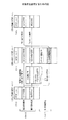
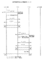
まず、図13に破線で示すように加入者電話44にかける場合について説明する。図14はこの場合の情報伝達シーケンスであり、そのステップは図12と対応している。図15はこの場合の呼設定メッセージを説明するための図である。図12のステップS40で内線電話38からPBX30に発信する。ステップS42でPBX30は図15にSM6で示す内線電話38の内線番号DNと着ID情報要素とを抽出する。着ID情報要素としてはPBX32の番号「710」と、ISDN公衆網34につながる局発特番「0」と、加入者電話44のIDである「06949YYYY」である。
【0030】
PBX30はステップS44で上記の発ID情報要素を用いて内線ダイヤルイン番号変換テーブル66を参照して内線電話38のダイヤルイン番号に変換する。ここでは、内線番号DNが「044777AAAA」に変換される。次にステップS46で着ID情報から接続先を判別するが、この場合は接続先がISDN中継線36であるのでステップS48に進む。ステップS48ではISDN中継線36の呼設定メッセージを設定する。ここでは図4に示すコードセット0の発ID情報要素M1に伝送先のPBX32のPBX番号「700」と、内線電話38の内線番号DNを設定する。また、コードセット0の着ID情報要素SM2に、着ID情報要素「710+0+06949YYYY」を設定し、コードセット7のPBXの内線のダイヤルイン番号M4にステップS44で変換したダイヤルイン番号「044777AAAA」を設定する。次のステップS50で上記のようにして設定した図15にSM7で示す呼設定メッセージを用いてPBX32に発信する。
【0031】
次にPBX32はステップS52でISDN中継線36の呼設定メッセージのコードセット7のPBXの内線のダイヤルイン番号「044777AAAA」を抽出し、またコードセット0の着ID情報要素を抽出する。次にステップS54で抽出した着ID情報要素から接続先を判別する。この場合接続先はISDN公衆網34の加入者電話44であるのでステップS56に進む。
【0032】
ステップS56ではステップS52で抽出した発信元の内線電話のダイヤルイン番号「044777AAAA」を図3に示すコードセット0の発ID情報要素M1に設定し、ステップS52で抽出した着ID情報要素「710+0+06949YYYY」からPBX番号及び局発特番「700+0+」を消去してコードセット0の着ID情報要素M2に設定し、コードセット7を消去した図15にSM8で示す呼設定メッセージを用いてISDN公衆網34に発信する。
【0033】
次にステップS58で加入者電話44の着信時に呼設定メッセージSM8で与えられた発ID情報要素つまりダイヤルイン番号「044777AAAA」を加入者電話44に設定し表示させる。これにより折り返し発信が可能となる。この後、ステップS60で加入者電話44が応答して内線電話38と加入者電話44との間の通話が行われる。
【0034】
次に、図16に破線で示すように加入者電話40にかける場合について説明する。図17はこの場合の情報伝達シーケンスであり、そのステップは図12と対応している。図18はこの場合の呼設定メッセージを説明するための図である。図12のステップS40で内線電話38からPBX30に発信する。ステップS42でPBX30は図18にSM6で示す内線電話38の内線番号DNと着ID情報要素とを抽出する。着ID情報要素としては「710+RRRR」である。
【0035】
PBX30はステップS44で上記の発ID情報要素を用いて内線ダイヤルイン番号変換テーブル66を参照して内線電話38のダイヤルイン番号に変換する。ここでは、内線番号DNが「044777AAAA」に変換される。次にステップS46で着ID情報から接続先を判別するが、この場合は接続先がISDN中継線36であるのでステップS48に進む。ステップS48ではISDN中継線36の呼設定メッセージを設定する。ここでは図4に示すコードセット0の発ID情報要素M1に伝送先のPBX32のPBX番号「700」と、内線電話38の内線番号DNとを設定する。また、コードセット0の着ID情報要素SM2に、着ID情報要素「710+RRRR」を設定し、コードセット7のPBXの内線のダイヤルイン番号M4にステップS44で変換したダイヤルイン番号「044777AAAA」を設定する。次のステップS50で上記のようにして設定した図18にSM7で示す呼設定メッセージを用いてPBX32に発信する。
【0036】
次にPBX32はステップS52でISDN中継線36の呼設定メッセージのコードセット7のPBXの内線のダイヤルイン番号「044777AAAA」を抽出し、またコードセット0の着ID情報要素を抽出する。次にステップS54で抽出した着ID情報要素から接続先を判別する。この場合接続先はPBX32の内線電話40であるのでステップS62に進む。ステップS62ではステップS52で抽出した発信元の内線電話38の発ID情報要素つまりダイヤルイン番号を着信時に内線電話40に設定し、内線電話40に内線電話38のダイヤルイン番号「044777AAAA」が表示され、折り返し発信が可能となる。この後、ステップS64で内線電話40の応答により加入者電話42,内線電話40間の通話が行われる。
【0037】
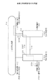
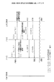
図19は内線電話38からPBX30,ISDN中継線36,PBX32を経由して内線電話40に電話をかけ、図20に破線で示すように公衆ISDN網34の加入者電話44に転送する場合のフローチャートを示す。図19において、図12と同一部分には同一符号を付す。図21はこの場合の情報伝達シーケンスであり、そのステップは図19と対応している。図19のステップS40で内線電話38からPBX30に発信する。ステップS42でPBX30は図18にSM6で示す内線電話38の内線番号DNと着ID情報要素とを抽出する。着ID情報要素としては「710+RRRR」である。
【0038】
PBX30はステップS44で上記の発ID情報要素を用いて内線ダイヤルイン番号変換テーブル66を参照して内線電話38のダイヤルイン番号に変換する。ここでは、内線番号DNが「044777AAAA」に変換される。次にステップS46で着ID情報から接続先を判別するが、この場合は接続先がISDN中継線36であるのでステップS48に進む。ステップS48ではISDN中継線36の呼設定メッセージを設定する。ここでは図4に示すコードセット0の発ID情報要素M1に伝送先のPBX32のPBX番号「700」と、内線電話38の内線番号DNとを設定する。また、コードセット0の着ID情報要素SM2に、着ID情報要素「710+RRRR」を設定し、コードセット7のPBXの内線のダイヤルイン番号M4にステップS44で変換したダイヤルイン番号「044777AAAA」を設定する。次のステップS50で上記のようにして設定した図18にSM7で示す呼設定メッセージを用いてPBX32に発信する。
【0039】
次にPBX32はステップS52でISDN中継線36の呼設定メッセージのコードセット7のPBXの内線のダイヤルイン番号「044777AAA」を抽出し、またコードセット0の着ID情報要素を抽出する。次にステップS54で抽出した着ID情報要素から接続先を判別する。この場合、接続先はPBX32の内線電話40であるのでステップS62に進む。ステップS62ではステップS52で抽出した発信元の内線電話38の発ID情報要素つまりダイヤルイン番号を着信時に内線電話40に設定し、内線電話40に内線電話38のダイヤルイン番号「044777AAAA」が表示される。この後、ステップS64で内線電話40の応答により加入者電話42,内線電話40間の通話が行われる。
【0040】
この通話によって加入者電話42の加入者が加入者電話44の加入者Yと通話したいことが分った場合には、ステップS70で内線電話40からISDN公衆網34の加入者電話44に転送操作により発信を行い、ステップS54に進む。このステップS54では接続先はISDN公衆網34の加入者電話44であるのでステップS56に進む。
【0041】
ステップS56ではステップS52で抽出した発信元の内線電話のダイヤルイン番号「044777AAAA」を図3に示すコードセット0の発ID情報要素M1に設定し、通話によってPBX30の内線電話38の人間がPBX32の内線電話の人間に口頭で伝えた「06949YYYY」をコードセット0の着ID情報要素M2に設定し、コードセット7を消去した図15にSM8で示す呼設定メッセージを用いてISDN公衆網34に発信する。
【0042】
次にステップS58で加入者電話44の着信時に呼設定メッセージSM8で与えられた発ID情報要素つまりダイヤルイン番号「044777AAAA」を加入者電話44に設定し表示させる。これにより折り返し発信が可能となる。この後、ステップS60で加入者電話44が応答して加入者電話44と内線電話40との間の通話が行われる。次にステップS74に進み、PBX32の内線電話40を切断した後、PBX32で内線電話38と加入者電話44とを接続し、これらの間の通話が行われる。
【0043】
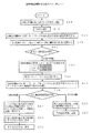
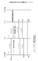
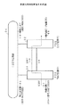
図22は加入者電話42からISDN公衆網34,PBX30を経由して内線電話38に電話をかけ、図23に示すようにPBX32の内線電話40に転送する場合のフローチャートを示す。図22において、図5と同一部分には同一符号を付す。図24はこの場合の情報伝達シーケンスであり、そのステップは図22と対応している。図22のステップS10でISDN公衆網34の加入者電話42からPBX30に発信する。これによってISDN公衆網34からPBX30に設定メッセージが供給される。設定(SETUP)メッセージSM1ではコードセット0の発ID情報要素として「044777XXXX」がセットされ、着ID情報要素として「044777EFGH」がセットされている。
【0044】
ステップS12でPBX30に着信すると、PBX30はステップS14で呼設定メッセージSM1のコードセット0から発ID情報要素及び着ID情報要素を抽出する。次にステップS16で抽出した着ID情報要素を用いてDIL変換テーブル65を参照してPBX32経由の着ID情報要素に変換する。ここでは、着ID情報要素が内線電話38を指示しているためステップS80に進み、呼設定メッセージから抽出した発ID情報要素を着信時に内線電話38に設定かつ表示させる。次にステップS82で内線電話38の応答により加入者電話42と内線電話38との間の通話が行われる。この通話によって加入者電話42の加入者がPBX32の内線電話と通話したいことが分った場合には、ステップS84で内線電話38からPBX32の内線電話40に転送操作により発信を行い、ステップS18に進む。
【0045】
次に、ステップS18では転送の着ID情報から接続先を判別するが、この場合は接続先がISDN中継線36であるのでステップS20に進む。ステップS20ではISDN中継線36の呼設定メッセージを設定する。ここでは図3に示すコードセット0の発ID情報要素M1に伝送先のPBX32のPBX番号「700」と、PBX30のISDN公衆網34の接続回線を示す局発特番「0」と、抽出した発ID情報要素「044777XXXX」とを設定する。また、コードセット0の着ID情報要素M2に、通話によって加入者電話42の加入者がPBX30の内線電話38の人間に口頭で伝えた「710+ZZZZ」を設定し、コードセット7の公衆発ID情報要素M3にステップS14で抽出した発ID情報要素「044777XXXX」を設定する。次のステップS22で上記のようにして設定した呼設定メッセージを用いてPBX32に発信する。
【0046】
次にPBX32はステップS24でISDN中継線36の呼設定メッセージのコードセット7の公衆発ID情報要素から加入者電話42の発ID情報要素「044777XXXX」を抽出し、またコードセット0の着ID情報要素を抽出する。次にステップS26で抽出した着ID情報要素から接続先を判別する。この場合、接続先はPBX32の内線電話40であるのでステップS28に進む。ステップS28ではステップS24で抽出した発信元の加入者電話42の発ID情報要素を着信時に内線電話40に設定し、内線電話40に加入者電話42の発ID情報要素「044777XXXX」が表示され、折り返し発信が可能となる。この後、ステップS30で内線電話40の応答により加入者電話42,内線電話40間の通話が行われる。
【0047】
次にステップS86に進み、PBX30の内線電話38を切断した後、PBX30で加入者電話42と内線電話40とを接続し、これらの間の通話が行われる。
【0048】
【発明の効果】
上述の如く、請求項1に記載の発明によれば、ISDN公衆網の加入者電話からPBXネットワーク網を経由して構内交換機の内線電話に発信した場合に、着信した内線電話に加入者電話の電話番号を通知でき、この着信した内線電話で発信元の電話番号の表示や折り返し発信が可能となり、内線電話からPBXネットワーク網を経由してISDN公衆網の加入者電話に発信した場合に、着信した加入者電話に発信した内線電話のダイヤルイン番号を通知でき、この着信した加入者電話で発信元のダイヤルイン番号の表示や折り返し発信が可能となる。
【0050】
また、請求項2に記載の発明によれば、ISDN公衆網の加入者電話からPBXネットワーク網を経由してISDN公衆網の加入者電話に発信した場合に、着信した加入者電話に発信元の加入者電話の電話番号を通知でき、この着信した加入者電話で発信元の電話番号の表示や折り返し発信が可能となり、内線電話からPBXネットワーク網を経由してISDN公衆網の加入者電話に発信した場合に、着信した加入者電話に発信した内線電話のダイヤルイン番号を通知でき、この着信した加入者電話で発信元のダイヤルイン番号の表示や折り返し発信が可能となる。
【0051】
また、請求項3に記載の発明によれば、ISDN公衆網の加入者電話からPBXネットワークの構内交換機の内線電話に着信して通信した後、PBXネットワーク網を経由して内線電話又はISDN公衆網の加入者電話に転送した場合に、転送された内線電話、又は加入者電話に発信元の加入者電話の電話番号を通知でき、転送された電話で発信元の電話番号の表示や折り返し発信が可能となる。
【0055】
また、請求項4に記載の発明によれば、内線電話からPBXネットワーク網を経由して内線電話に発信した後、ISDN公衆網の加入者電話に転送した場合に、転送された加入者電話に発信した内線電話のダイヤルイン番号を通知でき、この転送された加入者電話で発信元のダイヤルイン番号の表示や折り返し発信が可能となる。
【図面の簡単な説明】
【図1】本発明で用いるPBXのブロック図である。
【図2】本発明のPBXネットワーク網の構成図である。
【図3】呼設定メッセージのフォーマットを示す図である。
【図4】呼設定メッセージのフォーマットを示す図である。
【図5】本発明を説明するためのフローチャートである。
【図6】本発明を説明するための図である。
【図7】本発明を説明するための情報伝達シーケンスである。
【図8】本発明を説明するための図である。
【図9】本発明を説明するための図である。
【図10】本発明を説明するための情報伝達シーケンスである。
【図11】本発明を説明するための図である。
【図12】本発明を説明するためのフローチャートである。
【図13】本発明を説明するための図である。
【図14】本発明を説明するための情報伝達シーケンスである。
【図15】本発明を説明するための図である。
【図16】本発明を説明するための図である。
【図17】本発明を説明するための情報伝達シーケンスである。
【図18】本発明を説明するための図である。
【図19】本発明を説明するためのフローチャートである。
【図20】本発明を説明するための図である。
【図21】本発明を説明するための情報伝達シーケンスである。
【図22】本発明を説明するためのフローチャートである。
【図23】本発明を説明するための図である。
【図24】本発明を説明するための情報伝達シーケンスである。
【図25】PBXネットワーク網の構成図である。
【符号の説明】
30,32 PBX
34 ISDN公衆網
36 ISDN中継線
38,40 内線電話
42,44 加入者電話
46〜50 回線制御部
52 NW
54 CC
56 MM
60 メッセージ受信部
61 情報要素抽出部
62 情報要素制御部
63 情報要素編集部
64 メッセージ送信部
65 DIL変換テーブル
66 内線ダイヤルイン番号変換テーブル[0001]
BACKGROUND OF THE INVENTION
The present invention relates to a PBX network, and more particularly to a PBX network composed of a plurality of PBXs connected to a public ISDN network.
[0002]
[Prior art]
FIG. 25 shows a configuration diagram of the PBX network. In the figure, PBXs (private branch exchanges) 10 and 12 are connected to an ISDN (Integrated Services Digital Network) public network 14, and are connected to each other between extension telephones and to the
[0003]
In the conventional PBX network, the PBX number (for example, “700” for PBX10, “710” for PBX12, etc.) and the outgoing call ID (for example, extension telephone 18) in the message to the opposite PBX connected by the ISDN trunk line 16 are used. "A" and "B" for the extension telephone 20) are stored and notified.
[0004]
[Problems to be solved by the invention]
In the conventional PBX network, the
[0005]
Further, the
[0006]
The present invention has been made in view of the above points, and is capable of notifying the incoming telephone of the telephone number of the calling subscriber telephone and the dial-in number of the extension telephone in the telephone call via the ISDN trunk line of the PBX network. It is an object of the present invention to provide a PBX network that can display a telephone number and call back and improve convenience.
[0007]
[Means for Solving the Problems]
The invention according to
The private branch exchange is
When calling from a subscriber telephone of the ISDN public networkAs a supplementary service information element, a public ID information element which is a telephone number of a subscriber telephone that is transmitted in a call setting message of an ISDN trunk line protocolMeans to add,
An extension dial-in number conversion table for converting extension numbers of extension telephones to dial-in numbers;
When a call is made from an extension telephone, the dial-in number of the outgoing extension telephone is added as an additional service information element to the ISDN trunk line protocol call setup message.
Means to do.
[0008]
For this reason, when a call is made from a subscriber telephone of the ISDN public network to the extension telephone of the private branch exchange via the PBX network, the telephone number of the subscriber telephone can be notified to the received extension telephone. It is possible to display the caller's phone number and call backWhen an extension call is sent to the extension telephone of the private branch exchange via the PBX network, the extension telephone dial-in number can be notified to the received extension telephone. In-number display and call back are possible.
The invention according to
The private branch exchange is
When a call setup protocol notification is received from the ISDN trunk linePublic ID information element as the additional service information elementOr dial-in numberSet in the caller ID information element of the ISDN public network protocol call setup messageSaidCall ISDN public network subscriber phoneHave means.
[0009]
For this reason, when a call is made from a subscriber telephone of the ISDN public network to a subscriber telephone of the ISDN public network via the PBX network, the telephone number of the calling subscriber telephone can be notified to the incoming subscriber telephone. This incoming subscriber phone can display the caller's phone number and call back.Thus, when an extension telephone is sent to a subscriber telephone of the ISDN public network via the PBX network, the dial-in number of the extension telephone can be notified to the incoming subscriber telephone. It is possible to display the dial-in number of the sender and call backThe
The invention according to
The private branch exchange is
When calling from a subscriber telephone of the ISDN public networkAfter receiving and communicating with the extension telephone of the local exchange, a call is made to the PBX extension telephone or ISDN public network subscriber telephone through the ISDN trunk line by a transfer operation.Have means.
[0010]
For this reason, when an ISDN public network subscriber phone receives and communicates with an extension telephone of a private branch exchange of the PBX network, and then transfers to the extension telephone or ISDN public network subscriber telephone via the PBX network network, The telephone number of the calling subscriber's telephone can be notified to the transferred extension telephone or the subscriber telephone, and the calling telephone number can be displayed or returned by the transferred telephone.
[0013]
The invention according to
The private branch exchange is
When a call setup protocol notification is received from the ISDN trunk line, a call is received at the extension telephone of the local exchange and communicated, and thereafter, a means for making a call to a subscriber telephone of the ISDN public network by a transfer operation.
[0014]
For this reason, when a call is made from an extension telephone to an extension telephone via the PBX network and then transferred to a subscriber telephone of the ISDN public network, the dial-in number of the extension telephone sent to the transferred subscriber telephone is notified. It is possible to display the dial-in number of the caller and to make a return call on the transferred subscriber phone.
[0015]
DETAILED DESCRIPTION OF THE INVENTION
FIG. 2 shows a block diagram of an embodiment of the PBX network of the present invention. In the figure, the
[0016]
FIG. 1 shows a block diagram of an embodiment of the
[0017]
The
The MM (main memory) 56 is provided with an extension dial-in number conversion table 66 used for message conversion control in addition to line connection information such as the DIL conversion table 65 used when the
[0018]
The format of a call setup (SETUP) message used on the
[0019]
In FIG. 4, the call setting message code set 0 includes the caller ID information element M1 and the callee ID information element M2, and the code set 7 includes extension telephones of
The
[0020]
The information
[0021]
FIG. 5 shows a flowchart in the case of making a call from the
First, a case where the
[0022]
When an incoming call arrives at the
[0023]
Next, in step S24, the
[0024]
Next, a description will be given of a case where a call is made to the
[0025]
When an incoming call arrives at the
[0026]
Next, in step S24, the
[0027]
In step S32, the caller ID information element “0447777XXX” of the calling subscriber telephone extracted in step S24 is set in the caller ID information element M1 of code set 0 shown in FIG. 3, and the callee ID information element “0” extracted in step S24. 710 + 0 + 06949YYYY "is deleted from the PBX number and the local code" 700 + 0 + "and set in the called ID information element M2 of the code set 0, and the code set 7 is deleted.
[0028]
Next, in step S34, the calling ID information element “0447777XXX” given by the call setting message SM5 when the
FIG. 12 shows a flowchart for making a call from the
[0029]
First, a case where the
[0030]
In step S44, the
[0031]
Next, in step S52, the
[0032]
In step S56, the dial-in number "0447777AAA" of the caller extension telephone extracted in step S52 is set in the caller ID information element M1 of code set 0 shown in FIG. 3, and the called ID information element "710 + 0 + 06949YYYY" extracted in step S52. The PBX number and the local call special number “700 + 0 +” are deleted from the ID and set in the called ID information element M2 of the code set 0, and the code set 7 is deleted. send.
[0033]
In step S58, the calling ID information element given by the call setting message SM8, that is, the dial-in number “0447777AAA” is set and displayed on the
[0034]
Next, a case where the
[0035]
In step S44, the
[0036]
Next, in step S52, the
[0037]
FIG. 19 is a flowchart for calling from the
[0038]
In step S44, the
[0039]
Next, in step S52, the
[0040]
When it is found from this call that the subscriber of the
[0041]
In step S56, the dial-in number “0447777AAA” of the source extension telephone extracted in step S52 is set in the calling ID information element M1 of the code set 0 shown in FIG. 3, and the person of the
[0042]
In step S58, the calling ID information element given by the call setting message SM8, that is, the dial-in number “0447777AAA” is set and displayed on the
[0043]
FIG. 22 shows a flowchart in the case where a telephone is called from the
[0044]
When an incoming call arrives at the
[0045]
Next, in step S18, the connection destination is determined from the transfer destination ID information. In this case, since the connection destination is the
[0046]
Next, in step S24, the
[0047]
Next, in step S86, the
[0048]
【The invention's effect】
As described above, the invention described in claim 1According toWhen a call is made from an ISDN public telephone to a private branch exchange via the PBX network, the telephone number of the subscriber telephone can be notified to the incoming extension, and the call from the caller Display phone numbers and call backWhen an extension telephone is sent to a subscriber telephone of the ISDN public network via the PBX network, the dial-in number of the extension telephone can be notified to the incoming subscriber telephone. It is possible to display the dial-in number of the caller and call back.
[0050]
According to the invention of
[0051]
According to the invention of
[0055]
According to the invention as set forth in
[Brief description of the drawings]
FIG. 1 is a block diagram of a PBX used in the present invention.
FIG. 2 is a configuration diagram of a PBX network according to the present invention.
FIG. 3 is a diagram showing a format of a call setup message.
FIG. 4 is a diagram illustrating a format of a call setup message.
FIG. 5 is a flowchart for explaining the present invention.
FIG. 6 is a diagram for explaining the present invention.
FIG. 7 is an information transmission sequence for explaining the present invention.
FIG. 8 is a diagram for explaining the present invention.
FIG. 9 is a diagram for explaining the present invention.
FIG. 10 is an information transmission sequence for explaining the present invention.
FIG. 11 is a diagram for explaining the present invention.
FIG. 12 is a flowchart for explaining the present invention.
FIG. 13 is a diagram for explaining the present invention.
FIG. 14 is an information transmission sequence for explaining the present invention.
FIG. 15 is a diagram for explaining the present invention.
FIG. 16 is a diagram for explaining the present invention.
FIG. 17 is an information transmission sequence for explaining the present invention.
FIG. 18 is a diagram for explaining the present invention.
FIG. 19 is a flowchart for explaining the present invention.
FIG. 20 is a diagram for explaining the present invention.
FIG. 21 is an information transmission sequence for explaining the present invention.
FIG. 22 is a flowchart for explaining the present invention.
FIG. 23 is a diagram for explaining the present invention.
FIG. 24 is an information transmission sequence for explaining the present invention.
FIG. 25 is a configuration diagram of a PBX network.
[Explanation of symbols]
30, 32 PBX
34 ISDN public network
36 ISDN trunk line
38,40 extension telephone
42,44 subscriber phone
46-50 Line control unit
52 NW
54 CC
56 MM
60 Message receiver
61 Information element extraction unit
62 Information Element Control Unit
63 Information Element Editor
64 Message sending part
65 DIL conversion table
66 Extension dial-in number conversion table
Claims (4)
前記構内交換機は、
前記ISDN公衆網の加入者電話から発信されたとき前記ISDN中継線のプロトコルの呼設定メッセージに発信した加入者電話の電話番号である公衆発ID情報要素を付加サービス情報要素として追加する手段と、
内線電話の内線番号をダイヤルイン番号に変換する内線ダイヤルイン番号変換テーブルと、
内線電話から発信されたとき前記ISDN中継線のプロトコルの呼設定メッセージに、発信した内線電話のダイヤルイン番号を付加サービス情報要素として追加する
する手段を
有することを特徴とするPBXネットワーク網。In a PBX network in which a plurality of private branch exchanges connected to an ISDN public network are connected by an ISDN trunk line,
The private branch exchange is
Means for adding, as an additional service information element, a public ID information element that is a telephone number of a subscriber telephone that is transmitted to a call setting message of the ISDN trunk line protocol when the ISDN public network subscriber telephone is transmitted ;
An extension dial-in number conversion table for converting extension numbers of extension telephones to dial-in numbers;
When a call is made from an extension telephone, the dial-in number of the outgoing extension telephone is added as an additional service information element to the ISDN trunk line protocol call setup message.
Means to
A PBX network characterized by comprising a PBX network.
前記構内交換機は、
前記ISDN中継線から呼設定プロトコルの通知を受けたとき前記付加サービス情報要素としての公衆発ID情報要素またはダイヤルイン番号をISDN公衆網のプロトコルの呼設定メッセージの発ID情報要素に設定して前記ISDN公衆網の加入者電話に発信する手段を
有することを特徴とするPBXネットワーク網。The PBX network according to claim 1,
The private branch exchange is
The set to caller ID information element of the public onset ID information element or a dial-in number of the ISDN public network protocol of the call setting message as the additional service information element upon receiving a notification of the call setup protocol from the ISDN trunk line A means to make calls to ISDN public telephone subscriber phones
A PBX network characterized by comprising a PBX network.
前記構内交換機は、
前記ISDN公衆網の加入者電話から発信されたとき自交換機の内線電話に着信して通信後、転送操作により前記ISDN中継線を通してPBXの内線電話又はISDN公衆網の加入者電話に発信する手段を
有することを特徴とするPBXネットワーク網。In the PBX network according to claim 1 or 2,
The private branch exchange is
Means for making an outgoing call to the extension telephone of the local exchange when calling from a subscriber telephone of the ISDN public network and then making a call to a PBX extension telephone or an ISDN public network subscriber telephone through the ISDN trunk line by a transfer operation.
A PBX network characterized by comprising a PBX network.
前記構内交換機は、
前記ISDN中継線から呼設定プロトコルの通知を受けたとき自交換機の内線電話に着信して通信後、転送操作により前記ISDN公衆網の加入者電話に発信する手段を
有することを特徴とするPBXネットワーク網。 The PBX network according to claim 2,
The private branch exchange is
Means for receiving a call setting protocol notification from the ISDN trunk line and arriving at the extension telephone of the local exchange to communicate with a subscriber telephone of the ISDN public network by a transfer operation after communication.
A PBX network characterized by comprising a PBX network.
Priority Applications (2)
| Application Number | Priority Date | Filing Date | Title |
|---|---|---|---|
| JP04233197A JP3649842B2 (en) | 1997-02-26 | 1997-02-26 | PBX network |
| US08/989,790 US6633591B2 (en) | 1997-02-26 | 1997-12-12 | Switch device and system |
Applications Claiming Priority (1)
| Application Number | Priority Date | Filing Date | Title |
|---|---|---|---|
| JP04233197A JP3649842B2 (en) | 1997-02-26 | 1997-02-26 | PBX network |
Publications (2)
| Publication Number | Publication Date |
|---|---|
| JPH10243429A JPH10243429A (en) | 1998-09-11 |
| JP3649842B2 true JP3649842B2 (en) | 2005-05-18 |
Family
ID=12633035
Family Applications (1)
| Application Number | Title | Priority Date | Filing Date |
|---|---|---|---|
| JP04233197A Expired - Fee Related JP3649842B2 (en) | 1997-02-26 | 1997-02-26 | PBX network |
Country Status (2)
| Country | Link |
|---|---|
| US (1) | US6633591B2 (en) |
| JP (1) | JP3649842B2 (en) |
Families Citing this family (6)
| Publication number | Priority date | Publication date | Assignee | Title |
|---|---|---|---|---|
| KR100422927B1 (en) * | 1999-08-28 | 2004-03-12 | 엘지전자 주식회사 | Selective Call Pick-Up Method In Private Branch Exchange System |
| JP3827651B2 (en) * | 2003-04-28 | 2006-09-27 | Necインフロンティア株式会社 | External line transfer control method and system for network connection in private branch exchange |
| US20070070375A1 (en) * | 2005-09-22 | 2007-03-29 | Sharp Laboratories Of America, Inc. | Systems and methods for heuristics-based load balancing of hybrid PDL/raster printing |
| US20070070376A1 (en) * | 2005-09-22 | 2007-03-29 | Sharp Laboratories Of America, Inc. | Systems and methods for load balancing the creation of raster data and page description language data on a host |
| JP2009105937A (en) * | 2008-12-22 | 2009-05-14 | Ricoh Co Ltd | Communication device |
| WO2017181344A1 (en) * | 2016-04-19 | 2017-10-26 | 华为技术有限公司 | Communication method, apparatus and system |
Family Cites Families (15)
| Publication number | Priority date | Publication date | Assignee | Title |
|---|---|---|---|---|
| JP2675147B2 (en) * | 1989-07-14 | 1997-11-12 | 株式会社日立製作所 | Communication method |
| US5062108A (en) * | 1989-09-29 | 1991-10-29 | At&T Bell Laboratories | ISDN codeset conversion |
| JP2645602B2 (en) * | 1990-02-27 | 1997-08-25 | 富士通株式会社 | Analog trunk line-ISDN converter |
| JP2932673B2 (en) * | 1990-10-30 | 1999-08-09 | 日本電気株式会社 | Virtualized leased line method using ISDN network |
| JP2817105B2 (en) * | 1990-11-15 | 1998-10-27 | キヤノン株式会社 | Private branch exchange |
| US5185742A (en) * | 1990-12-31 | 1993-02-09 | At&T Bell Laboratories | Transparent signaling for remote terminals |
| JP3198351B2 (en) * | 1992-04-24 | 2001-08-13 | 富士通株式会社 | Call transfer control method |
| US5422943A (en) * | 1992-09-30 | 1995-06-06 | At&T Corp. | Private branch exchange networks |
| JPH06245240A (en) * | 1993-02-12 | 1994-09-02 | Nec Corp | System for connecting public line and private line |
| CA2110352C (en) * | 1993-02-26 | 1998-02-24 | Bruce Merrill Bales | Calling terminal controlled call coverage |
| AU672496B2 (en) * | 1993-06-21 | 1996-10-03 | Rpx Corporation | Communication system with ISDN as a backup of inter-PBX tie trunk |
| US5521970A (en) * | 1995-03-29 | 1996-05-28 | At&T Corp. | Arrangement for extending call-coverage across a network of nodes |
| US5818921A (en) * | 1996-03-14 | 1998-10-06 | Siemens Business Communication Systems, Inc. | Signaling system and method for enabling PBX-PBX feature transparency across a switched public network |
| US5912887A (en) * | 1996-06-27 | 1999-06-15 | Mciworldcom, Inc. | System and method for implementing user-to-user data transfer services |
| US5867568A (en) * | 1996-08-22 | 1999-02-02 | Lucent Technologies Inc. | Coverage of redirected calls |
-
1997
- 1997-02-26 JP JP04233197A patent/JP3649842B2/en not_active Expired - Fee Related
- 1997-12-12 US US08/989,790 patent/US6633591B2/en not_active Expired - Fee Related
Also Published As
| Publication number | Publication date |
|---|---|
| JPH10243429A (en) | 1998-09-11 |
| US6633591B2 (en) | 2003-10-14 |
| US20010043623A1 (en) | 2001-11-22 |
Similar Documents
| Publication | Publication Date | Title |
|---|---|---|
| CN1175686C (en) | Method and device for using a mobile phone in a wireless office network | |
| US5509062A (en) | Intelligent terminal based selective call forwarding | |
| US5978450A (en) | Personal dial tone | |
| US5761290A (en) | Alternate service activation | |
| JPH04291595A (en) | Virtual private network connecting system | |
| AU2002301410B2 (en) | Method and apparatus for serving of station group in internet protocol telephony exchange system | |
| JP3649842B2 (en) | PBX network | |
| JP2002199026A (en) | Communication terminal / information processing device cooperation method, computer-readable storage medium storing cooperation program, and communication system | |
| TW437243B (en) | Wireline telephony on a cellular switch | |
| KR100348291B1 (en) | Wireless local loop system for multi user and Method for operating the system | |
| JPH0685889A (en) | Call signal informing system | |
| JP3298602B2 (en) | Method and system for connecting extension from domestic virtual private network to international virtual private network | |
| JPH06269043A (en) | Mutual connection method between wireless networks | |
| JPH10257133A (en) | Communication equipment | |
| JPH0964983A (en) | Additional information transfer service method by ISDN trunk line | |
| JP2000270095A (en) | Exchange control method | |
| JPH06245241A (en) | Private network control method | |
| JPH01231592A (en) | Designated incoming system for isdn terminal | |
| JPH0282743A (en) | Communication terminal equipment | |
| JPH06113014A (en) | Electronic exchange system | |
| Lin | PBX based mobility manager for wireless local loop | |
| JPH06188979A (en) | Personal number call service method | |
| JPH05130147A (en) | Single access method | |
| JPH04200152A (en) | Closed area connection system | |
| JPH10108227A (en) | Interconnection device between private branch exchange and wireless service providing device |
Legal Events
| Date | Code | Title | Description |
|---|---|---|---|
| TRDD | Decision of grant or rejection written | ||
| A01 | Written decision to grant a patent or to grant a registration (utility model) |
Free format text: JAPANESE INTERMEDIATE CODE: A01 Effective date: 20050215 |
|
| A61 | First payment of annual fees (during grant procedure) |
Free format text: JAPANESE INTERMEDIATE CODE: A61 Effective date: 20050216 |
|
| R150 | Certificate of patent or registration of utility model |
Free format text: JAPANESE INTERMEDIATE CODE: R150 |
|
| FPAY | Renewal fee payment (event date is renewal date of database) |
Free format text: PAYMENT UNTIL: 20080225 Year of fee payment: 3 |
|
| FPAY | Renewal fee payment (event date is renewal date of database) |
Free format text: PAYMENT UNTIL: 20090225 Year of fee payment: 4 |
|
| FPAY | Renewal fee payment (event date is renewal date of database) |
Free format text: PAYMENT UNTIL: 20090225 Year of fee payment: 4 |
|
| FPAY | Renewal fee payment (event date is renewal date of database) |
Free format text: PAYMENT UNTIL: 20100225 Year of fee payment: 5 |
|
| FPAY | Renewal fee payment (event date is renewal date of database) |
Free format text: PAYMENT UNTIL: 20110225 Year of fee payment: 6 |
|
| FPAY | Renewal fee payment (event date is renewal date of database) |
Free format text: PAYMENT UNTIL: 20110225 Year of fee payment: 6 |
|
| FPAY | Renewal fee payment (event date is renewal date of database) |
Free format text: PAYMENT UNTIL: 20120225 Year of fee payment: 7 |
|
| FPAY | Renewal fee payment (event date is renewal date of database) |
Free format text: PAYMENT UNTIL: 20130225 Year of fee payment: 8 |
|
| FPAY | Renewal fee payment (event date is renewal date of database) |
Free format text: PAYMENT UNTIL: 20130225 Year of fee payment: 8 |
|
| FPAY | Renewal fee payment (event date is renewal date of database) |
Free format text: PAYMENT UNTIL: 20140225 Year of fee payment: 9 |
|
| LAPS | Cancellation because of no payment of annual fees |