JP3649837B2 - Cooking machine switch structure - Google Patents
Cooking machine switch structure Download PDFInfo
- Publication number
- JP3649837B2 JP3649837B2 JP01681797A JP1681797A JP3649837B2 JP 3649837 B2 JP3649837 B2 JP 3649837B2 JP 01681797 A JP01681797 A JP 01681797A JP 1681797 A JP1681797 A JP 1681797A JP 3649837 B2 JP3649837 B2 JP 3649837B2
- Authority
- JP
- Japan
- Prior art keywords
- switch
- cover
- drive
- cooking machine
- pushed
- Prior art date
- Legal status (The legal status is an assumption and is not a legal conclusion. Google has not performed a legal analysis and makes no representation as to the accuracy of the status listed.)
- Expired - Fee Related
Links
Images

Landscapes
- Food-Manufacturing Devices (AREA)
Description
【0001】
【発明の属する技術分野】
本発明は,例えば,ミキサーやスライサーなどの刃を備えた調理機のスイッチ構造に関するものである。
【0002】
【従来の技術】
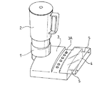
従来,ミキサーやスライサー等の調理機においては,図7に示すように,調理機本体1の上部に,着脱可能な調理用カップ2を備え,調理機本体1の操作部3に設けた駆動ボタン3Aを押して調理用カップ2の底部にある刃を回転させ,停止ボタン3Bを押して刃の回転を止めるようにしているものがある。そして,調理用カップ2の蓋2Aを開けているときに,誤って駆動ボタン3Aを押してしまうと突然中の刃が回転し始めるため,操作ボタン3Aをカバー4で覆っている。このカバー4はロッド5により操作部3の横から伸縮して駆動ボタン3Aをカバーするようになっている。
【0003】
【発明が解決しようとする課題】
しかしながら,このような駆動ボタン3Aのカバー4がついた調理機のスイッチ構造であっても,駆動ボタン3Aを押したままでもカバー4を閉鎖できるので,駆動ボタン3Aをオフにしてプラグをコンセントから抜いた後片づける間に、駆動ボタン3Aが押され、そのままカバー4を閉じてしまい込んだ状態が生ずると,次回の使用時に駆動ボタン3Aがオンになっていることに気付かないまま,プラグをコンセントに差し込んだ場合に,突然に刃が回転を始めるという問題がある。
【0004】
本発明は,このような問題に着目してなされたものであり,駆動スイッチのカバーを備えた調理機のスイッチ構造において,解除スイッチを押し込むと駆動スイッチをカバーが覆うことにより、不用意に駆動スイッチがONされない調理機のスイッチ構造を提案することを目的とする。
【0005】
【課題を解決するための手段】
上記課題を解決するために、本発明の請求項1の調理機のスイッチ構造は、調理機本体に、前記調理機本体側に押し込まれてオンとされることにより、調理室内に設けられた刃の回転を制御する駆動スイッチと、前記調理機本体側に押し込まれることにより、前記駆動スイッチをオフにする解除スイッチとを少なくとも備えている調理機のスイッチ構造であり、前記調理機本体の近傍には、前記解除スイッチのみが操作可動とされるように前記駆動スイッチを覆うことが可能なカバーが備えられ、前記カバーは、前記解除スイッチを押し込んだときに、前記カバーが前記駆動スイッチを覆うように構成されていることを特徴とする。
【0006】
本発明の請求項2の調理機のスイッチ構造は、請求項1の調理機のスイッチ構造であって、前記調理機本体には、前記駆動スイッチと前記解除スイッチとに係合して両者の操作を行う操作部材が配備され、この操作部材は、前記駆動スイッチを調理機本体側に押し込んだときに、前記駆動スイッチと係合して当該駆動スイッチの押し込み状態を保持する第1の係合手段と、前記解除スイッチを調理機本体側に押し込んだときに、第1の係合手段と前記駆動スイッチとの係合を外して前記駆動スイッチを押し込み前の突出状態に復帰させる第2の係合手段と、前記解除スイッチを調理機本体側に押し込んだときに、前記駆動スイッチを覆うように、前記カバーを操作する第3の係合手段とを、備えていることを特徴とする。
【0007】
本発明の請求項3の調理機のスイッチ構造は、請求項1又は請求項2の何れかの調理機のスイッチ構造において、前記カバーを開状態から閉状態に操作するときに、前記駆動スイッチをオフすることを特徴とする。
【0008】
【発明の実施の形態】
次に,本発明の好ましい実施形態にかかる調理機のスイッチ構造を図面に基づいて説明する。
【0009】
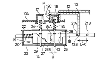
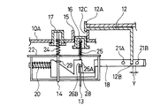
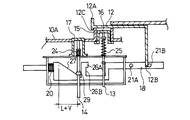
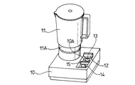
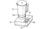
図1は,この実施形態にかかる調理機のスイッチ構造を示したものであり,図5,図6はこの実施形態の調理機のスイッチ構造が適用されるミキサーである。ミキサー本体10には,調理用カップ11が連結自在に搭載されており,調理用カップ11にはミキサーの刃が内蔵されている。調理用カップ11のミキサーの刃は底部11Aから突設されており,調理用カップ11の底部はネジを緩めることによりカップ本体から取り外すことができるようになっている。ミキサー本体10の操作部10Aには,カバー12がスライドして開閉するように設けられ,カバー12の内側に駆動スイッチ13,解除スイッチ14が配設されている。操作部10Aは矩形の凹部として形成され、駆動スイッチ13と解除スイッチ14との間には、区画壁15が設けられている。カバー12は凹部の開口部を区画壁15まで半分閉鎖できるようになっている。カバー12の先端部12Aは、区画壁15の上端部を乗り越えたときに、重力などの微力により簡単に開かないように、節度を持って係合するようになっている。駆動スイッチ13は押し込んで刃のモータをオンさせ,解除スイッチ14を押し込むと,駆動スイッチ13は上方に復帰する。
【0010】
図1は,この駆動スイッチ13と解除スイッチ14の配設状態を示した断面図であり,操作部10Aには,スイッチ機構が配設されている。スイッチ機構は刃を回転させるモータを駆動させる駆動ボタン16と,モータの回転を停止させる解除ボタン17とを有し,駆動スイッチ13の上端部には駆動ボタン16が設けられ,解除スイッチ14の上端部には解除ボタン17がかぶせられている。
【0011】
駆動スイッチ13の下方には、駆動スイッチ13の下端部に当接して導通する導通接点が配備されている。駆動スイッチ13の駆動ボタン16を図3のように押し込むと、導通接点が導通状態になって図示しない駆動モータが刃を回転させるようにオンとなる。駆動スイッチ13が図1に示すように突出状態にあると、導通接点が非導通となってモータはオフとなる。
【0012】
駆動スイッチ13と解除スイッチ14は、板金状のものであり、上下のフレーム22,23に上下動可能に保持されており、圧縮バネ24,25によりそれぞれ上方に付勢されている。圧縮バネ24、25は駆動スイッチ13、解除スイッチ14に設けた図示しない突起部とフレーム22との間に配備されている。
【0013】
駆動スイッチ13と解除スイッチ14の中間部には、制御用カム板18のカム部26,27に当接する突起部28,29が突設されている。
【0014】
駆動スイッチ13,解除スイッチ14の下側には、操作部材としての制御用カム板18が設けられている。制御用カム板18はスイッチ機構の矩形枠状のフレーム19に横方向にスライド可能に保持され,圧縮バネ20により制御用カム板18は右側に付勢されている。
【0015】
制御用カム板18の右側には,保持部26Bと、カム部27と、突起部21A、21Bとを有する。カム部26の保持部26Bは、駆動スイッチ13の駆動ボタン16をミキサ本体10側に押し込んだときに、駆動スイッチ13と係合して駆動スイッチ13の押し込み状態を保持する第1の係合手段を構成する。カム部27は、解除スイッチ14の解除ボタン17をミキサ本体10側に押し込んだときに、保持部26Bと駆動スイッチ14の突起部28との係合を外して駆動スイッチ13を押し込み前の突出状態に復帰させる第2の係合手段を構成する。
【0016】
突起部21Bは、解除スイッチ14をミキサ本体10側に押し込んだときに、駆動スイッチ13を覆うように、カバー12を操作する第3の係合手段を構成する。更に、突起部21Aは、カバー12を開状態から閉状態に操作するときに、駆動スイッチ13を突出状態に復帰させる第4の係合手段を構成する。
【0017】
駆動スイッチ13の突起部28が進入するカム部26は,突起部28が当接する角部が面取りされた導入部26Aと,導入部の下部を矩形にえぐるように形成された保持部26Bとを有する。駆動スイッチ13は下側に押されると,突起部28が導入部26Aを乗り越えて保持部26Bに入り,押圧状態を保持する。
【0018】
ここで、導入部26Aと駆動スイッチ13の突起部28との間には、距離Xの隙間が設けられている。この距離Xの隙間は、カバー12の下端部12Bが、突起部21Bに当接するときに、始めて導入部26Aと突起部28とを当接させるものであり、下端部12Bが突起部21Aに当たるときには、距離Xを隔てて導入部26Aと突起部28とを離間させる。
【0019】
この距離Xを設けて離間させることにより、カバー12が駆動スイッチ13のボタン16を覆うときに、突起部28が保持部26Bに保持されることが防止される。
【0020】
また、保持部26Bと導入部26Aとの間には距離Yが設けられている。距離Yは、スイッチ13を調理機本体奥に押し込むときに制御用カム板18が移動する距離である。導入部26Aが突起部28に突き当てられた状態で、駆動スイッチ13が押し込まれると、突起部28が導入部26Aを乗り越えて、保持部26Bに係合する。保持部26Bの縦縁部に突起部28が当接するとき、突起部21A、21Bはそれぞれ距離Yだけ右横に移動し、カバー12の下端部12Bと突起部21Bは離れる。
【0021】
従って、保持部26Bに突起部28が保持されてオン状態を維持するとき、制御用カム板18は図1の右横方向に距離X+Yの距離だけ移動している。
【0022】
一方、カバー12が駆動ボタン16を覆うときのカバー12の移動可能距離Lに対して、突起部21A、21Bの距離は(L−X)に設定されている。このため、開状態のカバー12を閉鎖して区画壁15と係合すると、下端部12Bに押された突起部21Aにより、制御用カム板18が距離Xだけ余分に左にスライドし、突起部28と導入部26Aとが距離Xをもって離間する。従って、駆動用ボタン16を押し込んでも、突起部28が保持部26Bに保持されることはない。
【0023】
解除スイッチ14は下側に押されると,突起部29がテーパー面からなるカム部27に入り込み,圧縮バネ20の弾発付勢力に抗して制御用カム板18を図1の左側に押す。このときの制御用カム板18のスライド量は距離(L+Y)であり、カバー12のスライド量はLである。図4に示すように、解除ボタン17を押し込むことにより、制御用カム板18は復帰動作を行い、カバー12の上端部12Aと区画壁15とが係合する。解除ボタン17の押し込み解除により、圧縮バネ20の弾発付勢力により制御用カム板18が図1に状態に戻り、突起部21Aがカバー12の下端部12Aに当接する。
【0024】
カバー12の水平部の左側先端部には,カバー12と区画壁15の上端部を乗り越えて係合する凸部12Cが形成されている。凸部12Cと区画壁15とが係合することによって、圧縮バネ20の付勢力で突起部21Aが下端部12Bを押圧しても、カバー12が閉じた状態が維持されるようになっている。
【0025】
ミキサ本体10をしまおうとして電源を抜いた後,間違えて駆動ボタン16を押したままの状態でも,カバー12を閉めて片づければ,駆動スイッチ13はオフ状態になり安全は確保される。
【0026】
この実施形態では,調理機本体10に設けた駆動スイッチ13のオンにより,調理用カップ11内の刃が駆動され,この駆動スイッチ13は,オン状態を維持可能とされる。調理機本体10に設けた解除スイッチ14により駆動スイッチ13はオンからオフになると共に、カバー12により駆動ボタン16が閉鎖される。オフになった駆動スイッチ13はカバー12により覆われていると共に,突起部28と導入部26Aが離れているので、駆動スイッチ13がオンになることはない。一方、カバー12は,開状態から閉状態に変えるときに,オン状態の駆動スイッチ13をオフとするので、駆動スイッチ13をオンさせたままカバー12を閉じても駆動スイッチ13が自動的にオフになる。従って、再度調理機本体10のコンセントを電源に接続しても刃が突然回転し始めることがない。
【0027】
【発明の効果】
本発明の請求項1の調理機のスイッチ構造によれば,解除スイッチを押し込めば、駆動スイッチが突出して押し込み状態が解消されると共に、駆動スイッチがカバーにより閉鎖される。従って、調理終了後は駆動スイッチがカバーされることから、不用意に駆動スイッチがオンしないため、再度調理機のコンセントを電源に接続しても刃が突然回転し始めることがない。
【0028】
本発明の請求項2の調理機のスイッチ構造によれば、駆動スイッチを押し込んでいる状態の時に、解除スイッチを押し込むと、第2の係合手段により、駆動スイッチが突出状態になって、駆動スイッチがオフになると共に、第3の係合手段により、駆動スイッチがカバーにより覆われる。従って、再度調理機のコンセントを電源に接続しても刃が突然回転し始めることがない。
【0029】
請求項3の調理機のスイッチ構造によれば、カバーを閉じると、駆動スイッチと第1の係合手段との係合状態が解消されて、駆動スイッチがオフとなるため、より確実に、再度調理機のコンセントをオンさせる時に突然刃が回転し始めるおそれがない。
【図面の簡単な説明】
【図1】 本発明の実施形態にかかる調理機のスイッチ構造の断面図であり,カバーを閉じて駆動スイッチをオフにした状態の断面図
【図2】 図1のスイッチ構造において、閉状態のカバーを開いて駆動スイッチをオン可能にした状態の断面図
【図3】 図2のスイッチ構造において、駆動スイッチをオンにした状態の断面図
【図4】 図3のスイッチ構造において、解除スイッチを押し込んで開状態のカバーを閉じ、駆動スイッチをオフにした状態の断面図
【図5】 本発明の実施形態の調理機であるミキサの斜視図であり,カバーを閉じた状態の斜視図
【図6】 本発明の実施形態の調理機であるミキサの斜視図であり,カバーを開いた状態の斜視図
【図7】 従来の調理機のスイッチ構造の斜視図
【符号の説明】
10 ミキサ本体(調理機本体)
11 調理用カップ
12 カバー
12B カバーの下端部
13 駆動スイッチ
14 解除スイッチ
18 制御用カム板(操作部材)
21A 突起部(第4の係合手段)
21B 突起部(第3の係合手段)
26B 保持部(第1の係合手段)
27 カム部(第2の係合手段)[0001]
BACKGROUND OF THE INVENTION
The present invention relates to a switch structure of a cooking machine having blades such as a mixer and a slicer.
[0002]
[Prior art]
Conventionally, in a cooking machine such as a mixer or a slicer, as shown in FIG. 7, a
[0003]
[Problems to be solved by the invention]
However, even with such a switch structure of a cooking machine with the cover 4 of the
[0004]
The present invention has been made paying attention to such a problem, and in a switch structure of a cooking machine having a cover of a drive switch, when the release switch is pushed in, the cover is covered by the cover so that the drive is inadvertently driven. It aims at proposing the switch structure of the cooking machine by which a switch is not turned ON.
[0005]
[Means for Solving the Problems]
In order to solve the above-described problem, the switch structure of the cooking machine according to
[0006]
The switch structure of the cooking machine according to
[0007]
Switch of a cooking machine according to claim 3 of the present invention, in the switch structure of one of the cooking machine according to
[0008]
DETAILED DESCRIPTION OF THE INVENTION
Next, the switch structure of the cooking device concerning preferable embodiment of this invention is demonstrated based on drawing.
[0009]
FIG. 1 shows a switch structure of a cooking machine according to this embodiment, and FIGS. 5 and 6 are mixers to which the switch structure of the cooking machine of this embodiment is applied. A
[0010]
FIG. 1 is a cross-sectional view showing a state in which the
[0011]
Below the
[0012]
The
[0013]
Projecting
[0014]
A
[0015]
On the right side of the
[0016]
The protruding portion 21 </ b> B constitutes a third engaging means for operating the
[0017]
The
[0018]
Here, a gap of a distance X is provided between the
[0019]
By providing and separating the distance X, when the
[0020]
A distance Y is provided between the holding
[0021]
Therefore, when the
[0022]
On the other hand, the distance between the
[0023]
When the
[0024]
A
[0025]
Even if the
[0026]
In this embodiment, the blade in the
[0027]
【The invention's effect】
According to the switch structure of the cooking machine of
[0028]
According to the switch structure of the cooking machine of
[0029]
According to the switch structure of the cooking machine of the third aspect, when the cover is closed, the engagement state between the drive switch and the first engagement means is canceled and the drive switch is turned off. There is no risk of the blades suddenly starting to turn on when the cooking appliance is turned on.
[Brief description of the drawings]
1 is a cross-sectional view of a switch structure of a cooking device according to an embodiment of the present invention, and is a cross-sectional view in a state where a cover is closed and a drive switch is turned off. FIG. FIG. 3 is a cross-sectional view of the switch structure of FIG. 2 with the cover open and the drive switch can be turned on. FIG. 4 is a cross-sectional view of the switch structure of FIG. FIG. 5 is a perspective view of a mixer that is a cooking machine according to an embodiment of the present invention, and is a perspective view of a state in which the cover is closed. 6 is a perspective view of a mixer which is a cooking machine according to an embodiment of the present invention, and is a perspective view with a cover opened. FIG. 7 is a perspective view of a switch structure of a conventional cooking machine.
10 Mixer body (cooking machine body)
DESCRIPTION OF
21A Protrusion (fourth engagement means)
21B Protrusion (third engagement means)
26B holding portion (first engaging means)
27 Cam portion (second engaging means)
Claims (3)
前記調理機本体には、前記駆動スイッチと前記解除スイッチとに係合して両者の操作を行う操作部材が配備され、
この操作部材は、
前記駆動スイッチを調理機本体側に押し込んだときに、前記駆動スイッチと係合して当該駆動スイッチの押し込み状態を保持する第1の係合手段と、
前記解除スイッチを調理機本体側に押し込んだときに、第1の係合手段と前記駆動スイッチとの係合を外して前記駆動スイッチを押し込み前の突出状態に復帰させる第2の係合手段と、
前記解除スイッチを調理機本体側に押し込んだときに、前記駆動スイッチを覆うように、前記カバーを操作する第3の係合手段とを、
備えていることを特徴とする調理機のスイッチ構造。A switch structure for a cooking machine according to claim 1,
The cooking device body is provided with an operation member that engages with the drive switch and the release switch to perform both operations,
This operating member is
A first engaging means that engages with the drive switch and holds the drive switch in a depressed state when the drive switch is pushed into the cooking machine body;
A second engagement means for releasing the engagement between the first engagement means and the drive switch when the release switch is pushed into the cooking machine main body, and returning the drive switch to the protruding state before being pushed; ,
A third engagement means for operating the cover so as to cover the drive switch when the release switch is pushed into the cooking machine body side;
The switch structure of the cooking machine characterized by having.
前記カバーを開状態から閉状態に操作するときに、前記駆動スイッチをオフすることを特徴とする調理機のスイッチ構造。In the switch structure of the cooking machine according to claim 1 or 2,
A switch structure for a cooking machine , wherein the drive switch is turned off when the cover is operated from an open state to a closed state.
Priority Applications (1)
| Application Number | Priority Date | Filing Date | Title |
|---|---|---|---|
| JP01681797A JP3649837B2 (en) | 1997-01-30 | 1997-01-30 | Cooking machine switch structure |
Applications Claiming Priority (1)
| Application Number | Priority Date | Filing Date | Title |
|---|---|---|---|
| JP01681797A JP3649837B2 (en) | 1997-01-30 | 1997-01-30 | Cooking machine switch structure |
Publications (2)
| Publication Number | Publication Date |
|---|---|
| JPH10211109A JPH10211109A (en) | 1998-08-11 |
| JP3649837B2 true JP3649837B2 (en) | 2005-05-18 |
Family
ID=11926733
Family Applications (1)
| Application Number | Title | Priority Date | Filing Date |
|---|---|---|---|
| JP01681797A Expired - Fee Related JP3649837B2 (en) | 1997-01-30 | 1997-01-30 | Cooking machine switch structure |
Country Status (1)
| Country | Link |
|---|---|
| JP (1) | JP3649837B2 (en) |
-
1997
- 1997-01-30 JP JP01681797A patent/JP3649837B2/en not_active Expired - Fee Related
Also Published As
| Publication number | Publication date |
|---|---|
| JPH10211109A (en) | 1998-08-11 |
Similar Documents
| Publication | Publication Date | Title |
|---|---|---|
| US6776086B1 (en) | Safety switch for a food processor | |
| CN102647931B (en) | Household cooking appliance comprising a work receptacle including an electric resistor | |
| GB2191555A (en) | Food processors | |
| CN201360959Y (en) | Household appliance for cooking preparation | |
| JP3093640U (en) | Food cooker safety protection mechanism | |
| JP3649837B2 (en) | Cooking machine switch structure | |
| CN210144535U (en) | Food processing cup and food processor | |
| CN100528055C (en) | Safety switch for kitchen utensils | |
| JP3771168B2 (en) | Electric cooker | |
| JP3034182B2 (en) | Cooking device | |
| JP4915451B2 (en) | Electric cooker | |
| CN110037583B (en) | A kind of food processing cup and food processor | |
| JP3097217U (en) | Food crusher with safety protection structure | |
| CN111603073B (en) | Bowl cover subassembly, stirring cup subassembly and cooking machine | |
| CN218528484U (en) | Container lid and liquid heating container | |
| KR20000016250U (en) | Electric hood mixer | |
| JPH02215418A (en) | Cooker | |
| JPH10117946A (en) | Switch structure for cooker | |
| JP2591349Y2 (en) | Safety mechanism of electric mixer | |
| CN223248055U (en) | Food processor | |
| CN215993624U (en) | Electric pressure cooker | |
| JPH0415154Y2 (en) | ||
| JP4385866B2 (en) | Electric cooker | |
| CN210727584U (en) | Cup body assembly and wall breaking machine with same | |
| JPS6115537B2 (en) |
Legal Events
| Date | Code | Title | Description |
|---|---|---|---|
| A131 | Notification of reasons for refusal |
Free format text: JAPANESE INTERMEDIATE CODE: A131 Effective date: 20041005 |
|
| A521 | Written amendment |
Free format text: JAPANESE INTERMEDIATE CODE: A523 Effective date: 20041203 |
|
| TRDD | Decision of grant or rejection written | ||
| A01 | Written decision to grant a patent or to grant a registration (utility model) |
Free format text: JAPANESE INTERMEDIATE CODE: A01 Effective date: 20050215 |
|
| A61 | First payment of annual fees (during grant procedure) |
Free format text: JAPANESE INTERMEDIATE CODE: A61 Effective date: 20050216 |
|
| R150 | Certificate of patent or registration of utility model |
Free format text: JAPANESE INTERMEDIATE CODE: R150 |
|
| FPAY | Renewal fee payment (event date is renewal date of database) |
Free format text: PAYMENT UNTIL: 20080225 Year of fee payment: 3 |
|
| S111 | Request for change of ownership or part of ownership |
Free format text: JAPANESE INTERMEDIATE CODE: R313113 |
|
| FPAY | Renewal fee payment (event date is renewal date of database) |
Free format text: PAYMENT UNTIL: 20080225 Year of fee payment: 3 |
|
| R350 | Written notification of registration of transfer |
Free format text: JAPANESE INTERMEDIATE CODE: R350 |
|
| FPAY | Renewal fee payment (event date is renewal date of database) |
Free format text: PAYMENT UNTIL: 20080225 Year of fee payment: 3 |
|
| FPAY | Renewal fee payment (event date is renewal date of database) |
Free format text: PAYMENT UNTIL: 20090225 Year of fee payment: 4 |
|
| FPAY | Renewal fee payment (event date is renewal date of database) |
Free format text: PAYMENT UNTIL: 20090225 Year of fee payment: 4 |
|
| S533 | Written request for registration of change of name |
Free format text: JAPANESE INTERMEDIATE CODE: R313533 |
|
| FPAY | Renewal fee payment (event date is renewal date of database) |
Free format text: PAYMENT UNTIL: 20090225 Year of fee payment: 4 |
|
| R360 | Written notification for declining of transfer of rights |
Free format text: JAPANESE INTERMEDIATE CODE: R360 |
|
| FPAY | Renewal fee payment (event date is renewal date of database) |
Free format text: PAYMENT UNTIL: 20090225 Year of fee payment: 4 |
|
| R360 | Written notification for declining of transfer of rights |
Free format text: JAPANESE INTERMEDIATE CODE: R360 |
|
| R371 | Transfer withdrawn |
Free format text: JAPANESE INTERMEDIATE CODE: R371 |
|
| S531 | Written request for registration of change of domicile |
Free format text: JAPANESE INTERMEDIATE CODE: R313531 |
|
| S533 | Written request for registration of change of name |
Free format text: JAPANESE INTERMEDIATE CODE: R313533 |
|
| FPAY | Renewal fee payment (event date is renewal date of database) |
Free format text: PAYMENT UNTIL: 20090225 Year of fee payment: 4 |
|
| R350 | Written notification of registration of transfer |
Free format text: JAPANESE INTERMEDIATE CODE: R350 |
|
| FPAY | Renewal fee payment (event date is renewal date of database) |
Free format text: PAYMENT UNTIL: 20100225 Year of fee payment: 5 |
|
| FPAY | Renewal fee payment (event date is renewal date of database) |
Free format text: PAYMENT UNTIL: 20100225 Year of fee payment: 5 |
|
| FPAY | Renewal fee payment (event date is renewal date of database) |
Free format text: PAYMENT UNTIL: 20110225 Year of fee payment: 6 |
|
| LAPS | Cancellation because of no payment of annual fees |