JP3649813B2 - Internal combustion engine exhaust pipe - Google Patents
Internal combustion engine exhaust pipe Download PDFInfo
- Publication number
- JP3649813B2 JP3649813B2 JP20593496A JP20593496A JP3649813B2 JP 3649813 B2 JP3649813 B2 JP 3649813B2 JP 20593496 A JP20593496 A JP 20593496A JP 20593496 A JP20593496 A JP 20593496A JP 3649813 B2 JP3649813 B2 JP 3649813B2
- Authority
- JP
- Japan
- Prior art keywords
- inner pipe
- upstream
- pipe
- downstream
- exhaust
- Prior art date
- Legal status (The legal status is an assumption and is not a legal conclusion. Google has not performed a legal analysis and makes no representation as to the accuracy of the status listed.)
- Expired - Fee Related
Links
Images
Landscapes
- Exhaust Silencers (AREA)
Description
【0001】
【発明の属する技術分野】
この発明は、内燃機関の排気管に関するものである。
【0002】
【従来の技術および課題】
従来のエンジンのエキゾーストマニホールドは、例えば4気筒エンジンの場合、第1気筒から第4気筒の爆発に同期した排気脈動により6k〜20kHzの高周波音がパイプ全体から発生しエンジン騒音における高周波異音の発生原因となっている。
【0003】
そこで、この発明の目的は、高周波音の発生を低減することにある。
【0004】
【課題を解決するための手段】
請求項1に記載の発明によれば、内燃機関の排気系の一部領域において、アウタパイプ部が排気脈動により振動する。この振動は上流側インナパイプ部の外周側および下流側インナパイプ部の外周側の少なくともいずれか一方に面接触する領域においてその伝達が減衰される。このように振動が減衰し、上流側インナパイプ部および下流側インナパイプ部の少なくともいずれか一方においては排気脈動による振動は弱いものとなり、高周波異音の発生が抑制される。
【0005】
請求項2に記載の発明によれば、エキゾーストマニホールドの曲がり部において排気ガスがアウタパイプ部に当たり、アウタパイプ部が排気脈動により振動する。この振動は上流側インナパイプ部の外周側および下流側インナパイプ部の外周側の少なくともいずれか一方に面接触する領域においてその伝達が減衰される。このように振動が減衰し、上流側インナパイプ部および下流側インナパイプ部の少なくともいずれか一方においては排気脈動による振動は弱いものとなり、高周波異音の発生が抑制される。
【0006】
請求項3に記載の発明によれば、上流側インナパイプ部と下流側インナパイプ部とアウタパイプ部はステンレス製であるので、気密状態にて接合する手法として全周溶接を用いることができる。
【0008】
【発明の実施の形態】
(第1の実施の形態)
以下、この発明の第1の実施の形態を図面に従って説明する。
【0009】
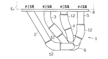
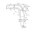
図1には本実施の形態におけるエキゾーストマニホールドの平面図を、図2には、エキゾーストマニホールドの正面図を示す。
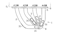
4気筒ガソリンエンジンEnには、エキゾーストマニホールド1が取り付けられている。ステンレス製エキゾーストマニホールド1は4つの分岐管2,3,4,5と1本の集合管6とを有している。即ち、第1気筒の排気ガスを排出するための第1気筒用分岐管2と、第2気筒の排気ガスを排出するための第2気筒用分岐管3と、第3気筒の排気ガスを排出するための第3気筒用分岐管4と、第4気筒の排気ガスを排出するための第4気筒用分岐管5とを備え、各分岐管が集合して集合管6と連通している。集合管6にはフロントパイプ7が接続されている。エキゾーストマニホールド1は取付けフランジ8,9によりエンジンEnおよびフロントパイプ7に取り付けられる。
【0010】
そして、エンジンEnの第1気筒〜第4気筒までの排気ガスは各気筒に対応した分岐管2〜5へ排出され、集合管6において全気筒の排気ガスが集合してフロントパイプ7に流れ、図示しないマフラーを通して大気に放出される。
【0011】
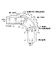
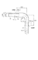
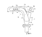
エキゾーストマニホールド1の曲がり部(図2中のA部)においては、図3に示すように、防振のための二重管構造となっている。つまり、ステンレス製の上流側インナパイプ部10と、ステンレス製の下流側インナパイプ部11と、ステンレス製のエルボ型アウタパイプ部12とを備えている。上流側インナパイプ部10はエンジンの排気系における上流側となり、上流側インナパイプ部10にエンジンの排気ガスが供給される。下流側インナパイプ部11はエンジンの排気系における下流側となり、下流側インナパイプ部11からエンジンの排気ガスが排出される。アウタパイプ部12は、上流側インナパイプ部10の外周側および下流側インナパイプ部11の外周側に所定長さ分だけ面接触するように配置されている。又、アウタパイプ部12は、上流側端面12aが上流側インナパイプ部10と気密状態にて接合されるとともに下流側端面12bが下流側インナパイプ部11と気密状態にて接合されている。より具体的には、全周溶接(外周溶接)により気密状態にて接合されている。図3においては溶接部を符号20,21にて示す。
【0012】
アウタパイプ部12が排気脈動により振動する部位となる。又、アウタパイプ部12の内周面と上流側インナパイプ部10の外周面との面接触部13が第1の振動伝達減衰部となるとともに、アウタパイプ部12の内周面と下流側インナパイプ部11の外周面との面接触部14が第2の振動伝達減衰部となる。
【0013】
第1の振動伝達減衰部(面接触部13)の長さL1は20〜40mmであり、第2の振動伝達減衰部(面接触部14)の長さL2は20〜40mmである。ここで、本実施の形態においては、曲がり部に面接触部13,14が配置されているので、長さL1,L2としてはパイプの中心での長さを指す。
【0014】
この構造(防振面接触二重管構造)は、エキゾーストマニホールド1の全ての曲がり部に採用されている。
次に、作用について述べる。
【0015】
一本のステンレス製分岐パイプを数箇所曲げることにより集合部に各分岐パイプを集合させた構造を採った場合にはパイプの曲がり部において排気により発生する圧力波が曲がり箇所においてパイプの管内壁に衝突し、そこで発生する高周波の振動がパイプ全体に伝わりエキゾーストマニホールド全体から同時にエンジン排気に同期した高周波異音が発生する。これに対し、本実施の形態においては以下の動作により高周波異音が低減する。
【0016】
エンジンからの排気ガスが曲がり部においてアウタパイプ部12の内壁に衝突し、その衝突により振動が発生する。この振動がアウタパイプ部12から上流側インナパイプ部10と下流側インナパイプ部11に伝達する。この際、第1および第2の振動伝達減衰部(パイプ面接触部13,14)において互いの管壁の干渉により振動の伝達が低減する。その結果、放射音が低減する。
【0017】
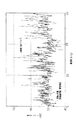
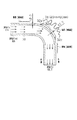
図4には、放射音低減効果についての騒音測定結果(実験結果)を示す。実験に用いたサンプルを図5に示す。図5において、上流側インナパイプ部10と下流側インナパイプ部11とアウタパイプ部12とは、全て、SUS304材を用い厚さは1mmである。パイプ寸法は、インナパイプ部10,11の外径が36mm、アウタパイプ部12の外径が38mmであり、インナパイプ部10,11の外周面とアウタパイプ部12の内周面とは0.05mmの間隔が設けられている。さらに、アウタパイプ部12はR70(曲げ半径70mm)である。第1の振動伝達減衰部(面接触部13)の長さL1は30mmであり、第2の振動伝達減衰部(面接触部14)の長さL2は30mmである。その他の寸法は図5に示すとおりである。
【0018】
又、エンジンには2000cc直列4気筒ガソリン噴射エンジンを用い、実験時のエンジン条件は1500rpm、負荷トルクは15kgfmである。これは特に高周波音の異音感を感じる条件である。さらに、マイクは管中心から20cmの位置に設置した。
【0019】
図4において、実線にて図5における構造(防振面接触二重管構造)を採用した場合を示し、二点鎖線にて外径が36mmで、R70のステンレスパイプ(単なる曲げパイプ)を用いた場合を示す。
【0020】
この図4から防振面接触二重管構造を採用したものの方が騒音低減効果があることが分かる。より正確には、6k〜20kHzのO.A値(オーバーオール値)で4dBの低減効果があることが分かった。
【0021】
このように、加振源となる箇所において加振力が同じであったも第1および第2の振動伝達減衰部(パイプ面接触部)にて振動を減衰させることができ、これにより、聴感で差ができる程度に放射音低減効果がある。
【0022】
このように本実施の形態は、下記の(イ),(ロ)の特徴を有する。
(イ)エキゾーストマニホールド1の曲がり部において、上流側インナパイプ部10と下流側インナパイプ部11とエルボ型アウタパイプ部12とからなる防振面接触二重管構造を採用したので、エキゾーストマニホールド1の曲がり部において排気ガスがアウタパイプ部12に当たり、アウタパイプ部12が排気脈動により振動するが、この振動はアウタパイプ部12と上流側インナパイプ部10との面接触部13においてその伝達が減衰されるとともにアウタパイプ部12と下流側インナパイプ部11との面接触部14においてその伝達が減衰される。このように振動が減衰し、上流側インナパイプ部10および下流側インナパイプ部11においては排気脈動による振動は弱いものとなり、高周波異音の発生が抑制される。
(ロ)上流側インナパイプ部10と下流側インナパイプ部11とアウタパイプ部12はステンレス製であるので、気密状態にて接合する手法として全周溶接を用いることができる。
【0023】
本実施の形態の応用例として、次のように実施してもよい。
上述した実施の形態ではエキゾーストマニホールドの曲がり部に適用したが、これに限ることなく、エキゾーストマニホールド以外の排気管(排気系)の一部領域に防振面接触二重管構造を設けることにより振動伝達を抑制して放射音を低減させる。又、曲がり部以外にも直線部等において防振面接触二重管構造を設けることにより振動伝達を抑制して放射音を低減させる。
【0024】
さらに、上述した実施の形態ではアウタパイプ部12は上流側インナパイプ部10の外周側および下流側インナパイプ部11の外周側に面接触するように配置し上流側端面12aおよび下流側端面12bを上流側インナパイプ部10および下流側インナパイプ部11と気密状態にて接合したが、アウタパイプ部12は上流側インナパイプ部10の外周側と下流側インナパイプ部11の外周側の内のいずれか一方にのみ面接触するように配置し、当該面接触部におけるアウタパイプ部12の端面(上流側あるいは下流側)をインナパイプ部の外周面(上流側インナパイプ部10の外周面あるいは下流側インナパイプ部11の外周面)と気密状態にて接合してもよい。
(第2の実施の形態)
次に、この発明の参考例としての第2の実施の形態を、第1の実施の形態との相違点を中心に説明する。
【0025】
図6には本実施の形態におけるエキゾーストマニホールドの平面図を、図7には、エキゾーストマニホールドの正面図を示す。
エキゾーストマニホールド1の曲がり部(図7中のB部)においては、図8に示すように、曲がり部の外側でのステンレスパイプ30の表面に制振用板材31が配置されている。制振用板材31は、ステンレス鋼板よりなり、長方形をなしている。縦・横の寸法は20mm×80mmで、厚さは2mmである。この制振用板材31は、その長手方向をステンレスパイプ30の延設方向とした状態で、長手方向における両端部と中央部の計3箇所において電気溶接(スポット溶接)によりパイプ30に点付けされ、パイプ30と面接触する状態で配置されている。図8において点付け箇所を32a,32b,32cにて示す。そして、パイプ30と制振用板材31との面接触部が排気脈動に対する振動減衰部となる。ステンレスパイプ30の厚さは2mmである。
【0026】
この制振用板材31は、図6,7に示すように、エンジンの第1気筒に対する排気管2には2箇所にわたり配置され、第2,第3,第4気筒に対する排気管3,4,5にそれぞれ1箇所ずつ配置されている。
【0027】
次に、作用について述べる。
エンジンからの排気ガスが圧力波となり曲がり部においてパイプ30の内壁に衝突し、その衝突によりパイプ30の表面が振動する。この振動がパイプ30の曲がり部から上流側と下流側に伝達する。この際、パイプ30と制振用板材31との間の面接触部において互いの壁面の干渉により振動の伝達が低減する。その結果、放射音が低減する。
【0028】
図9には、放射音低減効果についての騒音測定結果(実験結果)を示す。エンジンには2000cc直列4気筒ガソリン噴射エンジンを用い、実験時のエンジン条件は1500rpm、負荷トルクは15kgfmである。これは特に高周波音の異音感を感じる条件である。さらに、マイクはエンジンから40cmの位置に設置した。
【0029】
図9において、実線にて図8における構造(面接触プレート構造)を採用した場合を示し、二点鎖線にて曲げたステンレスパイプ(単なる曲げパイプ)を用いた場合を示す。
【0030】
この図9から面接触プレート構造を採用したものの方が騒音低減効果があることが分かる。より正確には、高周波異音を特に感じる1500rpm、15kgfmでO.A値(オーバーオール値)で3dBの低減効果があることが分かった。
【0031】
図10には、エンジン負荷を変えた時の6〜20kHzでの音圧レベルのO.A値(オーバーオール値)の測定結果を示す。尚、エンジン回転数は1500rpmで測定している。この図10からエンジン負荷が7kgfmよりも大きくなると図8における構造(面接触プレート構造)を採用したことによる騒音低減効果が表れることが分かる。
【0032】
このように本実施の形態は、下記の特徴を有する。
(イ)エキゾーストマニホールドの曲がり部におけるパイプ30の外側での表面に、制振用板材31を点付けして制振用板材31を面接触する状態で配置し、パイプ30と制振用板材31との面接触にて排気脈動に対する振動減衰を行うようにした。よって、エキゾーストマニホールドの曲がり部において排気ガスがパイプ30に当たりパイプ30が排気脈動により振動するが、この振動は曲がり部の外側でのパイプ表面において制振用板材31との面接触にてその伝達が減衰される。このように振動が減衰し、排気脈動による振動は弱いものとなり、高周波異音の発生が抑制される。
【0033】
又、エキゾーストマニホールドの曲がり部のパイプの厚さを厚くしマス効果により高周波異音の低減を図る場合に比べ、本実施の形態においてはコストアップや重量増加を招くこと無く高周波異音の低減を図ることができる。
【0034】
尚、上記実施の形態では1枚の制振用板材31に対し3箇所にわたり点付けしたが、その数は「3」以外の任意の数としてもよく、制振用板材31の大きさや厚さや材質等に応じた数とすればよい。
【図面の簡単な説明】
【図1】 第1の実施の形態におけるエキゾーストマニホールドの平面図。
【図2】 第1の実施の形態におけるエキゾーストマニホールドの正面図。
【図3】 第1の実施の形態におけるエキゾーストマニホールドの曲がり部の断面図。
【図4】 騒音測定結果を示す周波数特性図。
【図5】 実験に用いたサンプルの断面図。
【図6】 第2の実施の形態におけるエキゾーストマニホールドの平面図。
【図7】 第2の実施の形態におけるエキゾーストマニホールドの正面図。
【図8】 第2の実施の形態におけるエキゾーストマニホールドの曲がり部の断面図。
【図9】 騒音測定結果を示す周波数特性図。
【図10】 騒音測定結果を示す特性図。
【符号の説明】
En…ガソリンエンジン、1…エキゾーストマニホールド、10…上流側インナパイプ部、11…下流側インナパイプ部、12…アウタパイプ部、13,14…面接触部、30…パイプ、31…制振用板材。[0001]
BACKGROUND OF THE INVENTION
The present invention relates to an exhaust pipe of an internal combustion engine.
[0002]
[Prior art and problems]
For example, in the case of a four-cylinder engine, an exhaust manifold of a conventional engine generates high-frequency noise of 6 to 20 kHz from the entire pipe due to exhaust pulsation synchronized with the explosion from the first cylinder to the fourth cylinder. It is the cause.
[0003]
Accordingly, an object of the present invention is to reduce the generation of high frequency sound.
[0004]
[Means for Solving the Problems]
According to the first aspect of the present invention, the outer pipe portion vibrates due to exhaust pulsation in a partial region of the exhaust system of the internal combustion engine. Transmission of this vibration is attenuated in a region in surface contact with at least one of the outer peripheral side of the upstream inner pipe portion and the outer peripheral side of the downstream inner pipe portion. Thus, the vibration is attenuated, and the vibration due to the exhaust pulsation is weak in at least one of the upstream inner pipe portion and the downstream inner pipe portion, and the generation of high frequency noise is suppressed.
[0005]
According to the second aspect of the invention, the exhaust gas hits the outer pipe portion at the bent portion of the exhaust manifold, and the outer pipe portion vibrates due to the exhaust pulsation. Transmission of this vibration is attenuated in a region in surface contact with at least one of the outer peripheral side of the upstream inner pipe portion and the outer peripheral side of the downstream inner pipe portion. Thus, the vibration is attenuated, and the vibration due to the exhaust pulsation is weak in at least one of the upstream inner pipe portion and the downstream inner pipe portion, and the generation of high frequency noise is suppressed.
[0006]
According to the invention described in
[0008]
DETAILED DESCRIPTION OF THE INVENTION
(First embodiment)
A first embodiment of the present invention will be described below with reference to the drawings.
[0009]
FIG. 1 shows a plan view of the exhaust manifold in the present embodiment, and FIG. 2 shows a front view of the exhaust manifold.
An
[0010]
The exhaust gases from the first cylinder to the fourth cylinder of the engine En are discharged to the
[0011]
The bent portion (portion A in FIG. 2) of the
[0012]
The
[0013]
The length L1 of the first vibration transmission attenuation portion (surface contact portion 13) is 20 to 40 mm, and the length L2 of the second vibration transmission attenuation portion (surface contact portion 14) is 20 to 40 mm. Here, in the present embodiment, since the surface contact portions 13 and 14 are arranged at the bent portions, the lengths L1 and L2 indicate the lengths at the center of the pipe.
[0014]
This structure (anti-vibration surface contact double pipe structure) is employed in all the bent portions of the
Next, the operation will be described.
[0015]
In the case of adopting a structure in which each branch pipe is assembled at the gathering part by bending a single stainless steel branch pipe at several places, the pressure wave generated by the exhaust at the bent part of the pipe is applied to the pipe inner wall at the bent part. The high-frequency vibration generated in the collision is transmitted to the entire pipe, and high-frequency noise that is synchronized with the engine exhaust is generated from the entire exhaust manifold. On the other hand, in the present embodiment, high frequency abnormal noise is reduced by the following operation.
[0016]
Exhaust gas from the engine collides with the inner wall of the
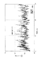
[0017]
In FIG. 4, the noise measurement result (experimental result) about a radiation sound reduction effect is shown. A sample used in the experiment is shown in FIG. In FIG. 5, the upstream
[0018]
Further, a 2000cc in-line four-cylinder gasoline injection engine is used as the engine, the engine conditions during the experiment are 1500 rpm, and the load torque is 15 kgfm. This is a condition in which a particularly high frequency sound is felt. Furthermore, the microphone was installed at a
[0019]
In FIG. 4, the solid line shows the case of adopting the structure shown in FIG. 5 (vibration-proof surface contact double pipe structure). Indicates the case where
[0020]
It can be seen from FIG. 4 that the vibration-proof surface contact double tube structure has a noise reduction effect. More precisely, an O.D. It was found that the A value (overall value) has a 4 dB reduction effect.
[0021]
In this way, even if the excitation force is the same at the location that becomes the excitation source, the first and second vibration transmission attenuation sections (pipe surface contact sections) can attenuate the vibrations. There is an effect of reducing radiated sound to the extent that the difference is possible.
[0022]
As described above, the present embodiment has the following features (A) and (B).
(A) Since the vibration-proof surface contact double pipe structure including the upstream
(B) Since the upstream
[0023]
As an application example of the present embodiment, the following may be implemented.
In the above-described embodiment, the present invention is applied to the bent portion of the exhaust manifold. However, the present invention is not limited to this, and vibration is generated by providing a vibration-proof surface contact double pipe structure in a partial area of the exhaust pipe (exhaust system) other than the exhaust manifold. Reduces radiated sound by suppressing transmission. Further, by providing a vibration-proof surface contact double tube structure in a straight part or the like other than the bent part, vibration transmission is suppressed and radiation noise is reduced.
[0024]
Further, in the above-described embodiment, the
(Second Embodiment)
Next, a second embodiment as a reference example of the present invention will be described focusing on differences from the first embodiment.
[0025]
FIG. 6 shows a plan view of the exhaust manifold in the present embodiment, and FIG. 7 shows a front view of the exhaust manifold.
In the bent portion of the exhaust manifold 1 (B portion in FIG. 7), as shown in FIG. 8, a damping
[0026]
As shown in FIGS. 6 and 7, the
[0027]
Next, the operation will be described.
The exhaust gas from the engine becomes a pressure wave and collides with the inner wall of the
[0028]
In FIG. 9, the noise measurement result (experimental result) about a radiation sound reduction effect is shown. A 2000cc in-line four-cylinder gasoline injection engine is used as the engine, the engine condition during the experiment is 1500 rpm, and the load torque is 15 kgfm. This is a condition in which a particularly high frequency sound is felt. Furthermore, the microphone was installed at a
[0029]
In FIG. 9, the solid line shows the case of adopting the structure (surface contact plate structure) in FIG.
[0030]
It can be seen from FIG. 9 that the surface contact plate structure has a noise reduction effect. More precisely, the O.D. It was found that the A value (overall value) has a 3 dB reduction effect.
[0031]
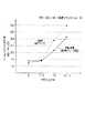
FIG. 10 shows the O.D. of the sound pressure level at 6 to 20 kHz when the engine load is changed. The measurement result of A value (overall value) is shown. The engine speed is measured at 1500 rpm. From FIG. 10, it can be seen that when the engine load becomes larger than 7 kgfm, the noise reduction effect by adopting the structure (surface contact plate structure) in FIG. 8 appears.
[0032]
Thus, the present embodiment has the following features.
(A) The damping
[0033]
Compared to increasing the thickness of the pipe at the bent part of the exhaust manifold and reducing the high frequency noise by the mass effect, this embodiment reduces the high frequency noise without increasing the cost and increasing the weight. Can be planned.
[0034]
In the above embodiment, three points are given to one
[Brief description of the drawings]
FIG. 1 is a plan view of an exhaust manifold according to a first embodiment.
FIG. 2 is a front view of an exhaust manifold according to the first embodiment.
FIG. 3 is a cross-sectional view of a bent portion of the exhaust manifold according to the first embodiment.
FIG. 4 is a frequency characteristic diagram showing a noise measurement result.
FIG. 5 is a cross-sectional view of a sample used in the experiment.
FIG. 6 is a plan view of an exhaust manifold according to a second embodiment.
FIG. 7 is a front view of an exhaust manifold according to a second embodiment.
FIG. 8 is a cross-sectional view of a bent portion of an exhaust manifold according to a second embodiment.
FIG. 9 is a frequency characteristic diagram showing a noise measurement result.
FIG. 10 is a characteristic diagram showing a noise measurement result.
[Explanation of symbols]
En ... Gasoline engine, 1 ... Exhaust manifold, 10 ... Upstream inner pipe part, 11 ... Downstream inner pipe part, 12 ... Outer pipe part, 13, 14 ... Surface contact part, 30 ... Pipe, 31 ... Damping plate material.
Claims (3)
内燃機関の排気系における上流側となる上流側インナパイプ部と、
内燃機関の排気系における下流側となる下流側インナパイプ部と、
前記上流側インナパイプ部の外周側および下流側インナパイプ部の外周側の少なくともいずれか一方に面接触するように配置され、上流側および下流側の少なくともいずれか一方の端面が前記上流側インナパイプ部および下流側インナパイプ部の少なくともいずれか一方と気密状態にて接合されたアウタパイプ部と
を備え、
排気脈動により振動する前記アウタパイプ部に対し、前記上流側インナパイプ部の外周側および下流側インナパイプ部の外周側の少なくともいずれか一方に面接触する領域を振動伝達減衰部としたことを特徴とする内燃機関の排気管。Provided in a partial region of the exhaust system of the internal combustion engine,
An upstream inner pipe that is upstream in the exhaust system of the internal combustion engine;
A downstream inner pipe that is downstream in the exhaust system of the internal combustion engine;
The upstream inner pipe part is disposed so as to be in surface contact with at least one of the outer peripheral side of the upstream inner pipe part and the outer peripheral side of the downstream inner pipe part, and at least one of the upstream and downstream end faces is the upstream inner pipe. And an outer pipe part joined in an airtight state with at least one of the part and the downstream inner pipe part,
A region that is in surface contact with at least one of the outer peripheral side of the upstream inner pipe portion and the outer peripheral side of the downstream inner pipe portion with respect to the outer pipe portion that vibrates due to exhaust pulsation is a vibration transmission attenuation portion. An exhaust pipe for an internal combustion engine.
内燃機関の排気系における上流側となる上流側インナパイプ部と、
内燃機関の排気系における下流側となる下流側インナパイプ部と、
前記上流側インナパイプ部の外周側および下流側インナパイプ部の外周側の少なくともいずれか一方に面接触するように配置され、上流側および下流側の少なくともいずれか一方の端面が前記上流側インナパイプ部および下流側インナパイプ部の少なくともいずれか一方と気密状態にて接合されたアウタパイプ部と
を備え、
排気脈動により振動する前記アウタパイプ部に対し、前記上流側インナパイプ部の外周側および下流側インナパイプ部の外周側の少なくともいずれか一方に面接触する領域を振動伝達減衰部としたことを特徴とする内燃機関の排気管。It is provided at the bent part of the exhaust manifold,
An upstream inner pipe that is upstream in the exhaust system of the internal combustion engine;
A downstream inner pipe that is downstream in the exhaust system of the internal combustion engine;
The upstream inner pipe part is disposed so as to be in surface contact with at least one of the outer peripheral side of the upstream inner pipe part and the outer peripheral side of the downstream inner pipe part, and at least one of the upstream and downstream end faces is the upstream inner pipe. And an outer pipe part joined in an airtight state with at least one of the part and the downstream inner pipe part,
A region that is in surface contact with at least one of the outer peripheral side of the upstream inner pipe portion and the outer peripheral side of the downstream inner pipe portion with respect to the outer pipe portion that vibrates due to exhaust pulsation is a vibration transmission attenuation portion. An exhaust pipe for an internal combustion engine.
Priority Applications (1)
| Application Number | Priority Date | Filing Date | Title |
|---|---|---|---|
| JP20593496A JP3649813B2 (en) | 1996-02-27 | 1996-08-05 | Internal combustion engine exhaust pipe |
Applications Claiming Priority (3)
| Application Number | Priority Date | Filing Date | Title |
|---|---|---|---|
| JP3995196 | 1996-02-27 | ||
| JP8-39951 | 1996-02-27 | ||
| JP20593496A JP3649813B2 (en) | 1996-02-27 | 1996-08-05 | Internal combustion engine exhaust pipe |
Publications (2)
| Publication Number | Publication Date |
|---|---|
| JPH09291818A JPH09291818A (en) | 1997-11-11 |
| JP3649813B2 true JP3649813B2 (en) | 2005-05-18 |
Family
ID=26379354
Family Applications (1)
| Application Number | Title | Priority Date | Filing Date |
|---|---|---|---|
| JP20593496A Expired - Fee Related JP3649813B2 (en) | 1996-02-27 | 1996-08-05 | Internal combustion engine exhaust pipe |
Country Status (1)
| Country | Link |
|---|---|
| JP (1) | JP3649813B2 (en) |
Families Citing this family (4)
| Publication number | Priority date | Publication date | Assignee | Title |
|---|---|---|---|---|
| JP4608109B2 (en) * | 2001-01-17 | 2011-01-05 | 三恵技研工業株式会社 | Engine exhaust system |
| GB2409238B (en) * | 2001-01-17 | 2005-07-27 | Sankei Giken Kogyo Kk | Engine exhaust system |
| JP4656014B2 (en) * | 2006-07-18 | 2011-03-23 | トヨタ自動車株式会社 | Exhaust system structure |
| JP5791477B2 (en) | 2011-11-25 | 2015-10-07 | 本田技研工業株式会社 | Exhaust device for internal combustion engine |
-
1996
- 1996-08-05 JP JP20593496A patent/JP3649813B2/en not_active Expired - Fee Related
Also Published As
| Publication number | Publication date |
|---|---|
| JPH09291818A (en) | 1997-11-11 |
Similar Documents
| Publication | Publication Date | Title |
|---|---|---|
| US8083025B2 (en) | Silencer provided on exhaust pipe of vehicle engine | |
| EP0373188A1 (en) | EXHAUST SILENCER SYSTEM FOR INTERNAL COMBUSTION ENGINE. | |
| JP3349089B2 (en) | exhaust manifold | |
| JPS59183018A (en) | Muffler | |
| CN112049710A (en) | Exhaust muffler device | |
| JP3649813B2 (en) | Internal combustion engine exhaust pipe | |
| JPH02180400A (en) | Damping double metal tube | |
| US5449866A (en) | Arrangement for damping sound in a pipe system | |
| JP3580945B2 (en) | Exhaust pipe of internal combustion engine | |
| EP1186769B1 (en) | Intake manifold for internal combustion engine | |
| JP3078253B2 (en) | Silencer for internal combustion engine | |
| JPH04234513A (en) | Exhaust system for multi-cylinder piston reciprocating engine | |
| JPH1162575A (en) | Exhaust pipe of internal combustion engine | |
| JP3937195B2 (en) | Silencer | |
| JP3394770B2 (en) | Silencer | |
| US11421569B2 (en) | Muffler | |
| JPH0452850B2 (en) | ||
| JP3505280B2 (en) | Electronic silencer | |
| US20200240299A1 (en) | Multi-chambered sound attenuation with resonant frequency targeting | |
| JPH09329013A (en) | Exhaust pipe noise reducing device | |
| JP2003206736A (en) | Exhaust manifold structure | |
| JPH053709Y2 (en) | ||
| JPS636406Y2 (en) | ||
| JP2594274Y2 (en) | Active silencer | |
| JPH11173144A (en) | exhaust manifold |
Legal Events
| Date | Code | Title | Description |
|---|---|---|---|
| A977 | Report on retrieval |
Free format text: JAPANESE INTERMEDIATE CODE: A971007 Effective date: 20040413 |
|
| A131 | Notification of reasons for refusal |
Free format text: JAPANESE INTERMEDIATE CODE: A131 Effective date: 20040420 |
|
| A521 | Written amendment |
Free format text: JAPANESE INTERMEDIATE CODE: A523 Effective date: 20040616 |
|
| A02 | Decision of refusal |
Free format text: JAPANESE INTERMEDIATE CODE: A02 Effective date: 20041026 |
|
| A521 | Written amendment |
Free format text: JAPANESE INTERMEDIATE CODE: A523 Effective date: 20041124 |
|
| A521 | Written amendment |
Free format text: JAPANESE INTERMEDIATE CODE: A523 Effective date: 20041208 |
|
| A911 | Transfer of reconsideration by examiner before appeal (zenchi) |
Free format text: JAPANESE INTERMEDIATE CODE: A911 Effective date: 20050118 |
|
| TRDD | Decision of grant or rejection written | ||
| A01 | Written decision to grant a patent or to grant a registration (utility model) |
Free format text: JAPANESE INTERMEDIATE CODE: A01 Effective date: 20050215 |
|
| A61 | First payment of annual fees (during grant procedure) |
Free format text: JAPANESE INTERMEDIATE CODE: A61 Effective date: 20050216 |
|
| R150 | Certificate of patent or registration of utility model |
Free format text: JAPANESE INTERMEDIATE CODE: R150 |
|
| FPAY | Renewal fee payment (event date is renewal date of database) |
Free format text: PAYMENT UNTIL: 20080225 Year of fee payment: 3 |
|
| FPAY | Renewal fee payment (event date is renewal date of database) |
Free format text: PAYMENT UNTIL: 20110225 Year of fee payment: 6 |
|
| LAPS | Cancellation because of no payment of annual fees |