JP3649810B2 - Heater fixing device for heater unit - Google Patents
Heater fixing device for heater unit Download PDFInfo
- Publication number
- JP3649810B2 JP3649810B2 JP17026596A JP17026596A JP3649810B2 JP 3649810 B2 JP3649810 B2 JP 3649810B2 JP 17026596 A JP17026596 A JP 17026596A JP 17026596 A JP17026596 A JP 17026596A JP 3649810 B2 JP3649810 B2 JP 3649810B2
- Authority
- JP
- Japan
- Prior art keywords
- heater
- insulator
- sheathed
- mounting plate
- sheathed heater
- Prior art date
- Legal status (The legal status is an assumption and is not a legal conclusion. Google has not performed a legal analysis and makes no representation as to the accuracy of the status listed.)
- Expired - Fee Related
Links
- 239000012212 insulator Substances 0.000 claims description 55
- 238000006073 displacement reaction Methods 0.000 claims description 6
- 238000003780 insertion Methods 0.000 description 3
- 230000037431 insertion Effects 0.000 description 3
- WABPQHHGFIMREM-UHFFFAOYSA-N lead(0) Chemical compound [Pb] WABPQHHGFIMREM-UHFFFAOYSA-N 0.000 description 2
- 238000007789 sealing Methods 0.000 description 2
- 230000004308 accommodation Effects 0.000 description 1
- 238000013459 approach Methods 0.000 description 1
- 238000009412 basement excavation Methods 0.000 description 1
- 230000008602 contraction Effects 0.000 description 1
- 230000006866 deterioration Effects 0.000 description 1
- 230000000694 effects Effects 0.000 description 1
- 239000011521 glass Substances 0.000 description 1
- 238000009413 insulation Methods 0.000 description 1
- 239000003566 sealing material Substances 0.000 description 1
- 238000010792 warming Methods 0.000 description 1
Images


Landscapes
- Electric Stoves And Ranges (AREA)
Description
【0001】
【発明の属する技術分野】
本発明は例えば長方形の電気コタツや長方形の掘コタツに最適なヒータユニットのヒータ固定装置に関する。
【0002】
【従来の技術】
長方形の電気コタツや掘コタツに使用するヒータユニットは採暖領域を広げるためにコタツ本体の形状に合わせて長方形としている。
【0003】
前述の様な長方形の電気コタツに長方形のヒータユニットを装着したものは実開昭63−159112号公報に開示されている。この様な先行技術に使用されるヒータは、コタツの短辺部側の温度を高めてコタツ内の各部の温度を均一にすべく複数本の直状のヒータを同一直線上に配置している。
【0004】
ところが、確かにこの様にヒータを同一直線上に配置した場合にはコタツの短辺部の中央部付近の温度が上昇するものの第1図に示すやぐらこたつ本体のコーナー部付近はそれ程温度が上昇せず温度ムラを生じた。
【0005】
この様な点を改良するために長方形のヒータユニットの取付板(反射板)に凵形に折り曲げて熱源領域を広くしたシーズヒータを取り付けたものが提案された。
【0006】
【発明が解決しようとする課題】
ところが、シーズヒータはもともと熱膨張率が高くなる性格を備えており、ヒータが直線形であって600度の高温の場合にはそれぞれの両端が約1〜2mmづつ膨張して伸長し、温度が低下した場合には収縮してほぼ元の長さに戻ることから、この伸縮の繰り返しによりシーズヒータの劣化を生じたり、端子の封口部に微小な隙間を生じ、この隙間から吸湿して絶縁不良を起たす原因となった。
【0007】
さらに、シーズヒータが凵形に成形している場合には、取付板に取り付けた状態において、シーズヒータが高温になると熱膨張して端子側の直線部分が直線方向に伸長し、同時にそれぞれの両端部が離れるようにして外側に変位する現象が現れ、封口部の絶縁不良を生じると共に誤ってヒータユニットを落下した場合には衝撃に伴って両端部が揺動し変位する欠点があった。
【0008】
本発明は上記の種々の点に鑑み、シーズヒータの熱膨張による伸長を抑え、且つ衝撃によって両端部が変位するのを防止したものである。
【0009】
【課題を解決するための手段】
本発明の第一は、平板状の取付板と、凵形であって両端部にフランジを有するシーズヒータと、このシーズヒータの中間部と両端部を前記取付板に絶縁固定する複数個の碍子とを備え、前記シーズヒータの両端部を固定する碍子は、シーズヒータの前記両端部のそれぞれを取付板から離間して掛止しシーズヒータと取付板とを絶縁する第一碍子と、シーズヒータの前記フランジと掛止しシーズヒータの直線方向への変位を規制する第二碍子とから構成し、さらに前記シーズヒータの中間部を固定する第三碍子を備え、前記第一碍子は、一側方を開放した収設部を有し、この収設部を前記取付板の内側に向けて固定し、前記シーズヒータの両端部を収設部に収設したものである。
【0010】
本発明の第二は、前記第一碍子と第二碍子は隣接して取付板に固定し、第一碍子と第二碍子で異方向からシーズヒータを抱持するようにしたものである。
【0011】
【発明の実施の形態】
本発明のヒータユニットのヒータ固定装置を長方形の電気コタツに実装した場合の実施例を図面に基づいて説明する。
【0012】
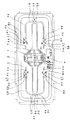
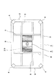
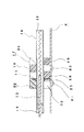
図1は本発明のヒータ固定装置を電気コタツに実装したヒータユニットの平面図、図2は同じくヒータユニットの取付状態を示す電気コタツの裏面図、図3は同じく要部断面図、図4は同じく要部分解斜視図、図5は同じく第二碍子の外観斜視図である。
【0013】
(1)は長方形の電気コタツ本体で、外桟(2)(2)(2)(2)及び内桟(3)(3)(3)(3)とコーナー部に設けた複数本の脚(4)(4)(4)(4)と内桟の中央部に装着した長方形のヒータユニット(5)とから構成している。
【0014】
前記ヒータユニット(5)の構成を詳述する。(6)は長方形で平板状の取付板、(7)は前記取付板(6)の中央部に取り付けた支持板、(8)は前記支持板(7)の上面に固定したモータで、ファン(9)を回転させる。(10)、(10)は前記取付板(6)に絶縁固定され前記ファン(9)を中心にして左右対称に配置した凵形のシーズヒータで、ヒータコイル(11)を内装し、このヒータコイルに接続したリード棒(12)を導出しており、折り曲げの中間部(13)、(13)と両端部(14)(14)、(14)(14)は後述する複数個の碍子により絶縁固定している。前記両端部(14)(14)、(14)(14)はシーズヒータに溶接した円形のフランジ(15)(15)を固定すると共に封口材(16)にて密封し、図1に示すようにファン(9)側に接近させて配置している。
【0015】
ここで、シーズヒータ(10)、(10)の固定構造を詳述する。(17)(17)…は下方に一対の支承片(18)(18)を有し、上方に該支承片間に位置する係当片(19)を有した平面形状がE型の第一碍子で、前記支承片(18)(18)と係当片(19)間には前記シーズヒータ(10)が微小空間を残して収設される程度の空間であって一側方を開放した収設部(20)を形成し、係当片(19)に隣接してネジ孔(21)を有している。
【0016】
(22)(22)…は図4のように∩形の挿入部(23)とネジ孔(24)(24)を設けた第二碍子で、図5のように挿入部(23)の一側面には、その内壁に段部(25)を形成している。
【0017】
(26)(26)は前記第一碍子(17)(17)…と同形状であって支承片(27)(27)と係当片(28)とネジ孔(図示せず)を有した平面形状がE型の第三碍子で、収設部(図示せず)を形成している。
【0018】
(29)は前記支持板(7)とシーズヒータ(10)、(10)の下方に装着したガードである。
【0019】
次にシーズヒータ(10)、(10)の固定動作を説明する。始めにネジ(30)(30)を第三碍子(26)(26)のネジ孔に挿通して、取付板(6)の両側に第三碍子(26)(26)を固定する。この時、それぞれの収設部は取付板(6)の中心側に向けて固定する。
【0020】
つづいて第一碍子(17)(17)…の収設部(20)(20)…を取付板(6)の内側に向けネジ(31)(31)…をネジ孔(21)(21)…に挿通して第一碍子を取付板(6)に固定する。
【0021】
斯して、シーズヒータ(10)、(10)の中間部(13)、(13)を第三碍子(26)、(26)の収設部に収設すると共にシーズヒータ(10)、(10)の両端部(14)(14)、(14)(14)を第一碍子(17)(17)、(17)(17)の収設部(20)(20)、(20)(20)に収設する。
【0022】
そして、第二碍子(22)(22)、(22)(22)の挿入部(23)(23)…内に前記シーズヒータ(10)、(10)の両端部(14)(14)、(14)(14)をはめた状態で第二碍子(22)(22)(22)(22)を第一碍子(17)(17)、(17)(17)方向にスライドして隣接させ、段部(25)(25)…と前記シーズヒータ(10)、(10)のフランジ(15)(15)…を掛止してネジ(32)(32)…をネジ孔(24)(24)…に挿通し第二碍子を取付板(6)に固定する。この結果、シーズヒータ(10)、(10)の両端部(14)(14)は、第一碍子の収設部と第二碍子の挿入部が異方向から抱持することになる。
【0023】
上述の様なシーズヒータ(10)、(10)の固定に伴い、このシーズヒータが発熱して高温となり熱膨張して両端部(14)(14)…に伸長するような作用が生じてもフランジ(15)(15)…が段部(25)(25)…に当たり、シーズヒータ(10)、(10)の直線方向への変位を規制する。この直線方向への伸長は、シーズヒータ(10)、(10)の中間部(13)、(13)を第三碍子(26)、(26)によって掛止していることから、シーズヒータのヒータユニット(5)の長手方向への移動が阻止されるために生ずるものである。
【0024】
そして、ヒータユニット(5)を装着した電気コタツ本体(1)或はヒータユニット(5)の単体を誤って落下した場合には、シーズヒータ(10)、(10)の両端部(14)(14)、(14)(14)がその衝撃によって左右に揺動するが、ヒータユニット(5)の外側方向への揺れは第一、第二碍子(17)(17)…、(22)(22)…によって抑えられ、ヒータユニット(5)の内側方向への揺れは第二碍子(22)(22)…の段部(25)(25)…とシーズヒータ(10)、(10)のフランジ(15)(15)…との掛止によって抑えられる。
【0025】
さらに、シーズヒータ(10)、(10)の温度上昇に伴って両端部(14)(14)、(14)(14)がヒータユニット(5)の外側方向へ変位すべく作用するが、この場合にも前述の落下の場合と同様に第一、第二碍子(17)(17)…、(22)(22)…によって抑えられる。
【0026】
【発明の効果】
以上の様に本発明は、第一硝子によって凵形のシーズヒータの両端部と取付板とを絶縁固定すると共に、第一碍子の収設部及び第二碍子によってシーズヒータの両端部が熱膨張に伴う伸長によって外側方向に拡開するのを阻止する。また第二碍子はシーズヒータの熱膨張に伴う伸長によって直線方向に変位するのを規制すると共に第一碍子と合わせて両端部が外側方向に拡開するのを防止する。第三碍子はシーズヒータの中間部を掛止して熱膨張に伴う伸長が分散するのを防止すると共にシーズヒータを水平状態を安定して保持する。
【0027】
さらに、第一碍子と第二碍子を隣接して取付板に固定し、且つシーズヒータを異方向から抱持したことにより、シーズヒータの一番変位の大きい端部を一層強固に固定できるのは勿論のこと、第一碍子によるシーズヒータの掛止部と第二碍子によるシーズヒータの掛止部とが接近し、仮に両端部が第二碍子に対して外側方向に拡開すべく作用しても第二碍子は第一碍子と当接してそれぞれの碍子が協働して変位を規制することができる。
【図面の簡単な説明】
【図1】本発明のヒータ固定装置を電気コタツに実装したヒータユニットの平面図である。
【図2】同じくヒータユニットの取付状態を示す電気コタツの裏面図である。
【図3】同じく要部断面図である。
【図4】同じく要部分解斜視図である。
【図5】同じく第二碍子の外観斜視図である。
【符号の説明】
5 ヒータユニット
6 取付板
10 シーズヒータ
13 中間部
14 両端部
15 フランジ
17 第一碍子
22 第二碍子
26 第三碍子[0001]
BACKGROUND OF THE INVENTION
The present invention relates to a heater fixing device for a heater unit that is most suitable for, for example, a rectangular electrical contact or a rectangular excavation contact.
[0002]
[Prior art]
The heater unit used for the rectangular electric kotatsu and digging kotatsu is rectangular in accordance with the shape of the kotatsu main body in order to widen the warming area.
[0003]
A rectangular electric unit with a rectangular heater unit as described above is disclosed in Japanese Utility Model Laid-Open No. 63-159112. In such a heater used in the prior art, a plurality of straight heaters are arranged on the same straight line in order to increase the temperature of the short side portion of the kotatsu and make the temperature of each part in the kotatsu uniform. .
[0004]
However, when the heaters are arranged on the same straight line, the temperature near the center of the short side of the kotatsu rises, but the temperature near the corner of the rattle kotatsu body shown in Fig. 1 rises that much. The temperature was uneven.
[0005]
In order to improve such a point, a rectangular heater unit mounting plate (reflecting plate) with a sheathed heater that is bent in a bowl shape to widen the heat source region has been proposed.
[0006]
[Problems to be solved by the invention]
However, the sheathed heater originally has the characteristic that the coefficient of thermal expansion is high. When the heater is linear and has a high temperature of 600 degrees, both ends expand and expand by about 1 to 2 mm, and the temperature is increased. If it drops, it shrinks and returns to its original length. Repeating this expansion and contraction causes deterioration of the sheathed heater and creates a minute gap in the terminal sealing part. Caused the problem.
[0007]
Furthermore, when the sheathed heater is molded in a bowl shape, when the sheathed heater is heated to a high temperature, the sheathed heater is thermally expanded and the linear portion on the terminal side extends in the linear direction. When the heater unit is accidentally dropped, there is a drawback that both ends swing and displace due to an impact when a phenomenon occurs in which the part is moved outward as the part moves away, resulting in poor insulation of the sealing part.
[0008]
In view of the above-described various points, the present invention suppresses expansion due to thermal expansion of a sheathed heater and prevents both end portions from being displaced by an impact.
[0009]
[Means for Solving the Problems]
The first of the present invention is a flat mounting plate, a sheathed heater having flanges at both ends, and a plurality of insulators for insulatingly fixing the intermediate portion and both ends of the sheathed heater to the mounting plate. And a first insulator for fixing the both ends of the sheathed heater to be separated from the mounting plate to insulate the sheathed heater from the mounting plate, and a sheathed heater. And a second insulator that latches and restrains the displacement of the sheathed heater in the linear direction, and further includes a third insulator that fixes an intermediate portion of the sheathed heater, and the first insulator is on one side The housing part is open toward the inside of the mounting plate, and the both ends of the sheathed heater are housed in the housing part.
[0010]
In the second aspect of the present invention, the first insulator and the second insulator are adjacently fixed to the mounting plate, and the sheath heater is held from different directions by the first insulator and the second insulator.
[0011]
DETAILED DESCRIPTION OF THE INVENTION
An embodiment in which the heater fixing device of the heater unit of the present invention is mounted on a rectangular electric contact will be described with reference to the drawings.
[0012]
FIG. 1 is a plan view of a heater unit in which the heater fixing device of the present invention is mounted on an electric kotatsu, FIG. 2 is a back view of the electric kotatsu showing the mounting state of the heater unit, FIG. FIG. 5 is an exploded perspective view of the main part, and FIG. 5 is an external perspective view of the second insulator.
[0013]
(1) is a rectangular electric kotatsu body, outer legs (2) (2) (2) (2) and inner bars (3) (3) (3) (3) and a plurality of legs provided at the corner (4) (4) (4) (4) and the rectangular heater unit (5) attached to the central portion of the inner rail.
[0014]
The configuration of the heater unit (5) will be described in detail. (6) is a rectangular and flat mounting plate, (7) is a support plate attached to the central portion of the mounting plate (6), and (8) is a motor fixed to the upper surface of the support plate (7). Rotate (9). (10) and (10) are saddle-shaped sheathed heaters that are insulated and fixed to the mounting plate (6) and arranged symmetrically about the fan (9). The lead rod (12) connected to the coil is led out, and the bent middle portions (13), (13) and both end portions (14), (14), (14), (14) are formed by a plurality of insulators to be described later. Insulated and fixed. The both end portions (14), (14), (14) and (14) are fixed with circular flanges (15) and (15) welded to a sheathed heater and sealed with a sealing material (16), as shown in FIG. Are arranged close to the fan (9) side.
[0015]
Here, the fixing structure of the sheathed heaters (10) and (10) will be described in detail. (17) (17) has a pair of support pieces (18) and (18) on the lower side, and a planar shape having an engagement piece (19) located between the support pieces on the upper side and is a first E-type. A space between the support pieces (18) (18) and the engagement piece (19) is a space where the sheathed heater (10) is accommodated leaving a minute space, and one side is opened. An accommodation part (20) is formed and has a screw hole (21) adjacent to the engaging piece (19).
[0016]
(22), (22)... Is a second insulator provided with a bowl-shaped insertion part (23) and screw holes (24) and (24) as shown in FIG. 4, and one of the insertion parts (23) as shown in FIG. On the side surface, a step (25) is formed on the inner wall.
[0017]
(26) (26) has the same shape as the first insulator (17), (17), and has support pieces (27), (27), engagement pieces (28), and screw holes (not shown). A planar shape is an E-type third insulator, and a receiving portion (not shown) is formed.
[0018]
(29) is a guard mounted below the support plate (7) and the sheathed heaters (10), (10).
[0019]
Next, the fixing operation of the sheathed heaters (10) and (10) will be described. First, the screws (30) and (30) are inserted into the screw holes of the third lever (26) and (26), and the third lever (26) and (26) are fixed to both sides of the mounting plate (6). At this time, each collecting portion is fixed toward the center side of the mounting plate (6).
[0020]
Next, the collecting portions (20), (20),... Of the first insulators (17), (17), are directed to the inside of the mounting plate (6), and the screws (31), (31), are screw holes (21, 21). Insert the first insulator into the mounting plate (6).
[0021]
Thus, the intermediate portions (13) and (13) of the sheathed heaters (10) and (10) are accommodated in the accommodating portions of the third insulators (26) and (26), and the sheathed heaters (10), ( 10) The two ends (14), (14), (14), (14) of the first insulators (17), (17), (17), (17), the receiving portions (20), (20), (20) ( 20).
[0022]
And in the insertion part (23) (23) ... of the second insulator (22) (22), (22) (22), both ends (14) (14) of the sheathed heater (10), (10), (14) Slide the second insulator (22), (22), (22), and (22) in the direction of the first insulator (17), (17), (17), and (17), with the second insulator (14) fitted. , And the flanges (15), (15) of the sheathed heaters (10), (10) are hooked and screws (32), (32) are screw holes (24) ( 24) Insert the second insulator into the mounting plate (6). As a result, the both ends (14) and (14) of the sheathed heaters (10) and (10) are held by the first insulator and the second insulator from different directions.
[0023]
When the sheathed heaters (10) and (10) are fixed as described above, even if the sheathed heater generates heat and becomes high temperature and thermally expands to extend to both ends (14) (14). The flanges (15), (15)... Hit the step portions (25), (25), and restrict the displacement of the sheathed heaters (10), (10) in the linear direction. The expansion in the linear direction is because the intermediate portions (13) and (13) of the sheathed heaters (10) and (10) are hooked by the third insulators (26) and (26). This is because the heater unit (5) is prevented from moving in the longitudinal direction.
[0024]
When the electric kotatsu body (1) or the heater unit (5) alone with the heater unit (5) is accidentally dropped, both ends (14) of the sheathed heaters (10) and (10) ( 14), (14), and (14) are swung to the left and right by the impact, but the heater unit (5) is swung outwardly from the first, second insulators (17), (17),. 22), and the inward movement of the heater unit (5) is caused by the step portions (25) (25) of the second insulators (22), (22), and the sheathed heaters (10), (10). It is restrained by hooking with the flanges (15), (15).
[0025]
Further, as the temperature of the sheathed heaters (10) and (10) rises, both end portions (14), (14), (14) and (14) act to displace outwardly of the heater unit (5). In this case, the first and second levers (17), (17),..., (22), (22).
[0026]
【The invention's effect】
As described above, the present invention insulates and fixes the both ends of the bowl-shaped sheathed heater and the mounting plate with the first glass, and the both ends of the sheathed heater are thermally expanded by the first insulator and the second insulator. To prevent it from expanding outward due to the expansion. In addition, the second insulator restricts displacement in the linear direction due to the expansion accompanying the thermal expansion of the sheathed heater, and prevents both end portions from expanding outwardly together with the first insulator. The third insulator hooks the intermediate portion of the sheathed heater to prevent the expansion due to thermal expansion from being dispersed and to keep the sheathed heater in a horizontal state stably.
[0027]
Furthermore, by fixing the first insulator and the second insulator to the mounting plate adjacent to each other and holding the sheathed heater from different directions, the end portion with the largest displacement of the sheathed heater can be more firmly fixed. Of course, the latching portion of the sheathed heater by the first insulator approaches the latching portion of the sheathed heater by the second insulator, and both end portions act to expand outwardly with respect to the second insulator. The second insulator can be in contact with the first insulator, and the respective insulators can cooperate to regulate displacement.
[Brief description of the drawings]
FIG. 1 is a plan view of a heater unit in which a heater fixing device of the present invention is mounted on an electric kotatsu.
FIG. 2 is a back view of the electric kotatsu showing a mounting state of the heater unit.
FIG. 3 is a cross-sectional view of the main part of the same.
FIG. 4 is an exploded perspective view of the main part of the same.
FIG. 5 is an external perspective view of the second insulator.
[Explanation of symbols]
5
Claims (2)
Priority Applications (1)
| Application Number | Priority Date | Filing Date | Title |
|---|---|---|---|
| JP17026596A JP3649810B2 (en) | 1996-06-28 | 1996-06-28 | Heater fixing device for heater unit |
Applications Claiming Priority (1)
| Application Number | Priority Date | Filing Date | Title |
|---|---|---|---|
| JP17026596A JP3649810B2 (en) | 1996-06-28 | 1996-06-28 | Heater fixing device for heater unit |
Publications (2)
| Publication Number | Publication Date |
|---|---|
| JPH1019273A JPH1019273A (en) | 1998-01-23 |
| JP3649810B2 true JP3649810B2 (en) | 2005-05-18 |
Family
ID=15901739
Family Applications (1)
| Application Number | Title | Priority Date | Filing Date |
|---|---|---|---|
| JP17026596A Expired - Fee Related JP3649810B2 (en) | 1996-06-28 | 1996-06-28 | Heater fixing device for heater unit |
Country Status (1)
| Country | Link |
|---|---|
| JP (1) | JP3649810B2 (en) |
-
1996
- 1996-06-28 JP JP17026596A patent/JP3649810B2/en not_active Expired - Fee Related
Also Published As
| Publication number | Publication date |
|---|---|
| JPH1019273A (en) | 1998-01-23 |
Similar Documents
| Publication | Publication Date | Title |
|---|---|---|
| US3991298A (en) | Heating unit for a ceramic top electric range | |
| US6921887B2 (en) | Microwave oven with bread toaster | |
| KR100435624B1 (en) | Evaporator with an electric heating cable for defrosting | |
| US2872558A (en) | Oven heating apparatus | |
| US2502044A (en) | Resistor support | |
| US5204498A (en) | Packaging assembly | |
| US4055723A (en) | Heater support element for electric furnace | |
| US2844703A (en) | Electric range oven | |
| JPH1019273A (en) | Heater fixing device for heater unit | |
| JPH0734392B2 (en) | PTC thermistor heating device | |
| KR200150293Y1 (en) | Quartz tube heater fixing structure of microwave oven | |
| US5144273A (en) | High limit thermostat apparatus | |
| US1456107A (en) | Electric resistance furnace | |
| US3440401A (en) | Thermal breaking means for front of baking oven | |
| KR200485353Y1 (en) | Over load device | |
| JP4058664B2 (en) | Circuit breaker arc extinguishing device | |
| KR101760375B1 (en) | Coolant heating apparatus | |
| CN223873758U (en) | Door body assembly and cooking utensil | |
| ES2320932T3 (en) | CARBON BRUSH HOLDER FOR AN ELECTRODINAMIC MACHINE. | |
| KR100720131B1 (en) | Insulator for PTC heater | |
| US5051717A (en) | High limit thermostat apparatus | |
| KR200391398Y1 (en) | Space heater | |
| JPS624806Y2 (en) | ||
| KR200183430Y1 (en) | Door for microwave oven | |
| KR20010060667A (en) | Door for microwave oven |
Legal Events
| Date | Code | Title | Description |
|---|---|---|---|
| A977 | Report on retrieval |
Free format text: JAPANESE INTERMEDIATE CODE: A971007 Effective date: 20040716 |
|
| A131 | Notification of reasons for refusal |
Free format text: JAPANESE INTERMEDIATE CODE: A131 Effective date: 20041102 |
|
| A521 | Written amendment |
Free format text: JAPANESE INTERMEDIATE CODE: A523 Effective date: 20041227 |
|
| TRDD | Decision of grant or rejection written | ||
| A01 | Written decision to grant a patent or to grant a registration (utility model) |
Free format text: JAPANESE INTERMEDIATE CODE: A01 Effective date: 20050208 |
|
| A61 | First payment of annual fees (during grant procedure) |
Free format text: JAPANESE INTERMEDIATE CODE: A61 Effective date: 20050216 |
|
| FPAY | Renewal fee payment (event date is renewal date of database) |
Free format text: PAYMENT UNTIL: 20090225 Year of fee payment: 4 |
|
| FPAY | Renewal fee payment (event date is renewal date of database) |
Free format text: PAYMENT UNTIL: 20090225 Year of fee payment: 4 |
|
| S533 | Written request for registration of change of name |
Free format text: JAPANESE INTERMEDIATE CODE: R313533 |
|
| FPAY | Renewal fee payment (event date is renewal date of database) |
Free format text: PAYMENT UNTIL: 20090225 Year of fee payment: 4 |
|
| R350 | Written notification of registration of transfer |
Free format text: JAPANESE INTERMEDIATE CODE: R350 |
|
| FPAY | Renewal fee payment (event date is renewal date of database) |
Free format text: PAYMENT UNTIL: 20090225 Year of fee payment: 4 |
|
| FPAY | Renewal fee payment (event date is renewal date of database) |
Free format text: PAYMENT UNTIL: 20100225 Year of fee payment: 5 |
|
| FPAY | Renewal fee payment (event date is renewal date of database) |
Free format text: PAYMENT UNTIL: 20110225 Year of fee payment: 6 |
|
| FPAY | Renewal fee payment (event date is renewal date of database) |
Free format text: PAYMENT UNTIL: 20110225 Year of fee payment: 6 |
|
| FPAY | Renewal fee payment (event date is renewal date of database) |
Free format text: PAYMENT UNTIL: 20120225 Year of fee payment: 7 |
|
| LAPS | Cancellation because of no payment of annual fees |