JP3649800B2 - Balcony scaffolding - Google Patents
Balcony scaffolding Download PDFInfo
- Publication number
- JP3649800B2 JP3649800B2 JP35119795A JP35119795A JP3649800B2 JP 3649800 B2 JP3649800 B2 JP 3649800B2 JP 35119795 A JP35119795 A JP 35119795A JP 35119795 A JP35119795 A JP 35119795A JP 3649800 B2 JP3649800 B2 JP 3649800B2
- Authority
- JP
- Japan
- Prior art keywords
- veranda
- scaffold
- attached
- ladder
- main column
- Prior art date
- Legal status (The legal status is an assumption and is not a legal conclusion. Google has not performed a legal analysis and makes no representation as to the accuracy of the status listed.)
- Expired - Fee Related
Links
- 239000000725 suspension Substances 0.000 claims description 6
- 239000004744 fabric Substances 0.000 description 4
- 239000000463 material Substances 0.000 description 3
- 238000010586 diagram Methods 0.000 description 2
- 238000010276 construction Methods 0.000 description 1
- 230000000694 effects Effects 0.000 description 1
- 238000009434 installation Methods 0.000 description 1
Images

Landscapes
- Movable Scaffolding (AREA)
Description
【0001】
【発明の属する技術分野】
本発明は、建物の建設工事中に外部足場からベランダ及びバルコニーの手摺壁や、腰窓等の腰壁等を越えて建物のベランダ等に移動したり、逆に、ベランダ等から外部足場に移動するためのベランダ足場に関する。
【0002】
【従来の技術】
従来のこの種のベランダ足場としては、歩み板の両側に梯子を設けた、いわゆる脚立構造のものを、一方の梯子の下端部を外部足場に据え付けると共に、他方の梯子の下端部をベランダスラブ面上に据え付けて、上記手摺壁等を跨ぐ状態でセットされていた。
【0003】
【発明が解決しようとする課題】
しかしながら、上記従来のベランダ足場は、梯子の下端部がベランダスラブ面上に据え付けられるため、該スラブの仕上げ作業時に梯子の下端が邪魔になって、ベランダ足場全体を移設しなければならないだけでなく、据え付け状態が不安定で危険である等の問題点があった。また、ベランダ乗り越え時に、頭が上階のベランダスラブに当たって危険もあった。
【0004】
本発明は上記従来の課題を解決するためになされたもので、その目的とするところは、ベランダスラブ等の仕上げ作業の妨げになる恐れがなく、安定かつ確実にセットしたり、簡単に折り畳んでコンパクトに運搬や保管することが可能なベランダ足場を提供することにある。また、踏板を跨いでベランダを乗り越えることもでき、安全に使用することができるベランダ足場を提供する。
【0005】
【課題を解決するための手段】
本発明のベランダ足場は、連結杆によりほぼ平行に連結される主柱と、該主柱を外部足場に取り付けて支持する取付手段から成る本体フレームと;上端部が上記主柱の上端部に回動自在に枢着されると共に、下端部がベランダスラブ面の上方に離れて位置する縦材と、該縦材に取り付けられる数段の踏板から成る吊梯子と;から構成されることを特徴とする。また、連結杆によりほぼ平行に連結される主柱と、該主柱を外部足場に取り付けて支持する取付手段から成る本体フレームと;上記主柱の上端部にほぼ直交して取り付けられる手摺杆と、上端部が該手摺杆に回動自在に枢着されると共に、下端部がベランダスラブ面の上方に離れて位置する縦材と、該縦材に取り付けられる数段の踏板から成る吊梯子と;から構成されることを特徴とする。さらに、上記本体フレームと吊梯子の間に踏板を取り付けることを特徴とする。又更に、上記踏板を着脱自在に取り付けることを特徴とする。更にまた、上記吊梯子の下端部に突張り杆を回動自在に枢着することを特徴とする。
【0006】
【発明の実施の形態】
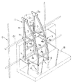
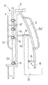
以下、本発明の一実施例について図面を参照しながら説明する。図1および図2において、1は本体フレームであって、2本の主柱1aと、これらの主柱1aを相互にほぼ平行に連結する連結杆1bと、上記主柱1aの中間部および下端部に付設されたフック1cから構成されている。該フック1cは外部足場Gに水平に組み付けられた横支持材G1に掛け止められて、上記本体フレーム1を外部足場Gに取り付けるようになっている。上記主柱1aの上端部には手摺杆2がほぼ直交して取り付けられている。
【0007】
3は吊梯子であって、2本のほぼ平行な縦材3aと、該縦材3aの間に取り付けられた数段(本実施例では3段)の踏杆3bから構成されている。該縦材3aの上端部は、ピン2aにより上記手摺杆2に回動自在に枢着されている。なお、上記手摺杆2を省略して、上記縦材3aを主柱1aの上端部に直接枢着せしめることも可能である。
【0008】
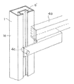
4は踏板であって、ガイド杆4aに着脱自在に取り付けられている。上記ガイド杆4aの一端側はピン4bにより上記縦杆3aに回動自在に枢着されており、他端側は上記主柱1aに摺動自在に取り付けられている。さらに詳細には、主柱1aの内側に沿設された溝杆5の溝5aに、上記ガイド杆4aの端部に植設されたピン4cを挿設して、上記溝5aに沿って上下にスライド可能に取り付ける。従って、上記吊梯子3は、図2に仮想線で示すように、折り畳み可能に組み付けられている。なお、図3に示すように、上記溝杆5を省略して、上記主柱1aの内側に溝a′を形成し、該溝a′にピン4bを直接挿設してもよい。また、最上部の連結杆1bに上記ピン4bあるいはその取付部を当設せしめて、上記ガイド杆4aの摺動のストッパー機能を持たせてもよい。
【0009】
上記吊梯子3の縦材3aの下端部には、突張り杆6が取り付けられている。該突張り杆6は矢印方向に回転自在に枢着されていると共に、適宜長さに伸縮できるように調整可能に且つ使用時には固定できるように構成されている。該突張り杆6の先端には当接板6aが付設されていて、ベランダBに当接して上記吊梯子3を安定して保持する。
【0010】
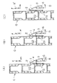
図4は、ベランダBに対する外部足場Gの床付布枠G2の位置関係が異なる場合の、本発明のベランダ足場のセット状態を示すもので、それぞれの場合に、ベランダ足場の踏板4と外部足場Gの床付布枠G2を使用して移動することが可能であるが、特に(C)の場合には、踏板4を取り外した状態で、ベランダBの壁を跨ぐようにして、ベランダ足場の踏杆3bから外部足場Gの床付布枠G2に直接踏み入れるように使用することにより、上階のベランダスラブB′に頭があたる恐れがない。なお、この(C)の場合においても、踏板4を取り外すことなく、直接、これを跨いでもよい。
【0011】
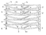
図5は、上記ベランダ足場を折り畳んで、積み重ねた状態を示すもので、上記手摺杆2を使用して順次積み重ねると共に、上記突張り杆6を使用して順次積み重ねることにより、各ベランダ足場をほぼ水平に保った状態で整然と積み重ねることができる。
【0012】
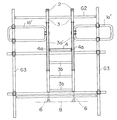
図6および図7は、別の実施例を示すもので、上記吊梯子3の縦材3aに手摺3a′を付設し、また、上記主柱1aの外側に補助手摺1a′を設けてある。該補助手摺1a′は外部足場Gの縦支持材G3に固定されるようになっている。
【0013】
【発明の効果】
ベランダスラブ等の仕上げ作業の妨げになる恐れがなく、安定かつ確実にセットしたり、簡単に折り畳んでコンパクトに運搬や保管することが可能である。また、踏板が取り外し可能になっているので、ベランダ乗り越え時に、頭が上階のベランダスラブに当たる恐れがない。
【図面の簡単な説明】
【図1】本発明のベランダ足場の一実施例の斜視図である。
【図2】図1のベランダ足場を外部足場にセットした状態の側面図である。
【図3】ベランダ足場と外部足場のセット状態の位置関係の説明図である。
【図4】スライド構造の別の実施例を示す説明図である。
【図5】ベランダ足場を折り畳んで積み重ねた状態の説明図である。
【図6】ベランダ足場の別の実施例の側面図である。
【図7】図6の正面図である。
【符号の説明】
1 本体フレーム
1a 主柱
1a′補助手摺
1b 連結杆
1c フック
2 手摺杆
2a ピン
3 吊梯子
3a 縦材
3a′手摺
3b 踏板
3c ピン
4 踏板
4a ガイド杆
4b ピン
4c ピン
5 溝杆
5a 溝
6 突張り杆
6a 当接板
a′溝
B ベランダ
G 外部足場
G1 横支持材
G2 床付布枠
G3 縦支持材[0001]
BACKGROUND OF THE INVENTION
The present invention moves from the external scaffolding to the veranda of the building over the handrail wall of the veranda and balcony, the waist wall of the waist window, etc. during the construction work of the building, or conversely from the veranda etc. to the external scaffolding Concerning the veranda scaffold for
[0002]
[Prior art]
As this type of conventional veranda scaffold, a so-called stepladder structure in which ladders are provided on both sides of the step board, the lower end of one ladder is installed on an external scaffold, and the lower end of the other ladder is placed on the veranda slab surface. It was set up so as to straddle the handrail wall and the like.
[0003]
[Problems to be solved by the invention]
However, since the lower end of the ladder is installed on the veranda slab surface in the conventional veranda scaffold, not only the lower end of the ladder becomes an obstacle when finishing the slab, but the entire veranda scaffold must be moved. There was a problem that the installation state was unstable and dangerous. In addition, there was a danger that the head hit the veranda slab on the upper floor when getting over the veranda.
[0004]
The present invention has been made in order to solve the above-described conventional problems, and the object of the present invention is to stably and surely set or fold it easily without causing a hindrance to finishing work such as a veranda slab. It is to provide a veranda scaffold that can be transported and stored in a compact manner. In addition, a veranda scaffold that can be used over the veranda over the tread board and can be used safely is provided.
[0005]
[Means for Solving the Problems]
The veranda scaffold according to the present invention includes a main column that is connected substantially in parallel by a connecting rod, and a main body frame that includes attachment means for attaching and supporting the main column to an external scaffold; and an upper end portion that rotates around the upper end portion of the main column. A vertical member that is pivotally movable and has a lower end portion that is located above the veranda slab surface, and a suspension ladder that includes a plurality of steps attached to the vertical member. To do. A main column connected substantially in parallel by a connecting rod; and a main body frame comprising attachment means for attaching and supporting the main column to an external scaffold; and a handrail rod attached substantially orthogonal to the upper end of the main column; A vertical member whose upper end is pivotally attached to the handrail, and whose lower end is located above the veranda slab surface, and a suspended ladder made up of several steps attached to the vertical member, It is characterized by comprising. Furthermore, a tread is attached between the main body frame and the suspended ladder. Still further, the step board is detachably attached. Furthermore, a projecting rod is pivotally attached to the lower end portion of the suspension ladder.
[0006]
DETAILED DESCRIPTION OF THE INVENTION
Hereinafter, an embodiment of the present invention will be described with reference to the drawings. 1 and 2, reference numeral 1 denotes a main body frame, two main pillars 1a, a connecting rod 1b for connecting these main pillars 1a substantially in parallel with each other, and an intermediate portion and a lower end of the main pillar 1a. It is comprised from the hook 1c attached to the part. The hook 1c is hooked on a lateral support member G1 horizontally mounted on the external scaffold G, so that the main body frame 1 is attached to the external scaffold G. A
[0007]
[0008]
[0009]
A
[0010]
FIG. 4 shows the set state of the veranda scaffold of the present invention when the positional relationship of the floor-attached cloth frame G2 of the external scaffold G with respect to the veranda B is different. In each case, the
[0011]
FIG. 5 shows a state in which the veranda scaffolds are folded and stacked. The veranda scaffolds are sequentially stacked using the
[0012]
6 and 7 show another embodiment, in which a
[0013]
【The invention's effect】
There is no possibility of hindering finishing work such as a veranda slab, and it can be set stably and reliably, or it can be easily folded and transported and stored compactly. In addition, since the treadle is removable, there is no risk of the head hitting the veranda slab on the upper floor when riding over the veranda.
[Brief description of the drawings]
FIG. 1 is a perspective view of an embodiment of a veranda scaffold of the present invention.
FIG. 2 is a side view of the veranda scaffold shown in FIG. 1 set on an external scaffold.
FIG. 3 is an explanatory diagram of a positional relationship between a veranda scaffold and an external scaffold in a set state.
FIG. 4 is an explanatory view showing another embodiment of the slide structure.
FIG. 5 is an explanatory diagram of a state in which veranda scaffolds are folded and stacked.
FIG. 6 is a side view of another embodiment of a veranda scaffold.
7 is a front view of FIG. 6. FIG.
[Explanation of symbols]
DESCRIPTION OF SYMBOLS 1 Main body frame 1a Main pillar 1a 'Auxiliary handrail 1b Connecting
Claims (5)
Priority Applications (1)
| Application Number | Priority Date | Filing Date | Title |
|---|---|---|---|
| JP35119795A JP3649800B2 (en) | 1995-12-27 | 1995-12-27 | Balcony scaffolding |
Applications Claiming Priority (1)
| Application Number | Priority Date | Filing Date | Title |
|---|---|---|---|
| JP35119795A JP3649800B2 (en) | 1995-12-27 | 1995-12-27 | Balcony scaffolding |
Publications (2)
| Publication Number | Publication Date |
|---|---|
| JPH09177309A JPH09177309A (en) | 1997-07-08 |
| JP3649800B2 true JP3649800B2 (en) | 2005-05-18 |
Family
ID=18415713
Family Applications (1)
| Application Number | Title | Priority Date | Filing Date |
|---|---|---|---|
| JP35119795A Expired - Fee Related JP3649800B2 (en) | 1995-12-27 | 1995-12-27 | Balcony scaffolding |
Country Status (1)
| Country | Link |
|---|---|
| JP (1) | JP3649800B2 (en) |
Families Citing this family (1)
| Publication number | Priority date | Publication date | Assignee | Title |
|---|---|---|---|---|
| GB2595867B (en) * | 2020-06-08 | 2025-04-23 | Mydek Ltd | Balcony access apparatus, balcony access system and balcony access method |
-
1995
- 1995-12-27 JP JP35119795A patent/JP3649800B2/en not_active Expired - Fee Related
Also Published As
| Publication number | Publication date |
|---|---|
| JPH09177309A (en) | 1997-07-08 |
Similar Documents
| Publication | Publication Date | Title |
|---|---|---|
| JPH10506444A (en) | Scaffold assembly | |
| RU2008124808A (en) | FOLDING PLATFORM | |
| EP1989374B1 (en) | Plastic platform for a foldable ladder and combination of a plastic platform and foldable ladder | |
| JP3649800B2 (en) | Balcony scaffolding | |
| JP3429655B2 (en) | Work scaffold | |
| JP3044376B2 (en) | Scaffolding platform for telescopic work and telescopic top plate | |
| CA2305199A1 (en) | Laterally assisting platform support | |
| KR100937838B1 (en) | A stairs tpye and collapsible ladder | |
| KR200344096Y1 (en) | An extension ladder | |
| JP4037964B2 (en) | Assembly type scaffolding | |
| JP3351598B2 (en) | Folding construction work scaffold | |
| KR200452778Y1 (en) | Working scaffolding | |
| US2265730A (en) | Window scaffold | |
| JP4170580B2 (en) | Portable worktable | |
| JP3176208B2 (en) | Multiple ladder with movable hook device | |
| JPH0860856A (en) | Veranda scaffold | |
| JP2003247338A (en) | Work table | |
| JPH07229287A (en) | Telescopic scaffolding equipment | |
| JPH11182166A (en) | Expansion pipe structure of ascending/descending frame and opening frame | |
| KR100536099B1 (en) | A ladder using architerture | |
| JPH0740592Y2 (en) | Universal workbench | |
| KR20060110136A (en) | Ladder | |
| JP4690602B2 (en) | Workbench with handrail | |
| KR20160095407A (en) | protect for upset system of A type aluminium ladder | |
| JP4038424B2 (en) | Workbench with handrail |
Legal Events
| Date | Code | Title | Description |
|---|---|---|---|
| RD04 | Notification of resignation of power of attorney |
Free format text: JAPANESE INTERMEDIATE CODE: A7424 Effective date: 20040226 |
|
| A521 | Written amendment |
Free format text: JAPANESE INTERMEDIATE CODE: A821 Effective date: 20040227 |
|
| A977 | Report on retrieval |
Free format text: JAPANESE INTERMEDIATE CODE: A971007 Effective date: 20040428 |
|
| A131 | Notification of reasons for refusal |
Free format text: JAPANESE INTERMEDIATE CODE: A131 Effective date: 20040518 |
|
| A521 | Written amendment |
Free format text: JAPANESE INTERMEDIATE CODE: A523 Effective date: 20040714 |
|
| TRDD | Decision of grant or rejection written | ||
| A01 | Written decision to grant a patent or to grant a registration (utility model) |
Free format text: JAPANESE INTERMEDIATE CODE: A01 Effective date: 20050118 |
|
| A61 | First payment of annual fees (during grant procedure) |
Free format text: JAPANESE INTERMEDIATE CODE: A61 Effective date: 20050216 |
|
| R150 | Certificate of patent or registration of utility model |
Free format text: JAPANESE INTERMEDIATE CODE: R150 |
|
| S111 | Request for change of ownership or part of ownership |
Free format text: JAPANESE INTERMEDIATE CODE: R313115 |
|
| R360 | Written notification for declining of transfer of rights |
Free format text: JAPANESE INTERMEDIATE CODE: R360 |
|
| R370 | Written measure of declining of transfer procedure |
Free format text: JAPANESE INTERMEDIATE CODE: R370 |
|
| S111 | Request for change of ownership or part of ownership |
Free format text: JAPANESE INTERMEDIATE CODE: R313115 |
|
| FPAY | Renewal fee payment (event date is renewal date of database) |
Free format text: PAYMENT UNTIL: 20080225 Year of fee payment: 3 |
|
| R350 | Written notification of registration of transfer |
Free format text: JAPANESE INTERMEDIATE CODE: R350 |
|
| FPAY | Renewal fee payment (event date is renewal date of database) |
Free format text: PAYMENT UNTIL: 20090225 Year of fee payment: 4 |
|
| FPAY | Renewal fee payment (event date is renewal date of database) |
Free format text: PAYMENT UNTIL: 20100225 Year of fee payment: 5 |
|
| FPAY | Renewal fee payment (event date is renewal date of database) |
Free format text: PAYMENT UNTIL: 20100225 Year of fee payment: 5 |
|
| FPAY | Renewal fee payment (event date is renewal date of database) |
Free format text: PAYMENT UNTIL: 20110225 Year of fee payment: 6 |
|
| FPAY | Renewal fee payment (event date is renewal date of database) |
Free format text: PAYMENT UNTIL: 20110225 Year of fee payment: 6 |
|
| FPAY | Renewal fee payment (event date is renewal date of database) |
Free format text: PAYMENT UNTIL: 20120225 Year of fee payment: 7 |
|
| FPAY | Renewal fee payment (event date is renewal date of database) |
Free format text: PAYMENT UNTIL: 20130225 Year of fee payment: 8 |
|
| FPAY | Renewal fee payment (event date is renewal date of database) |
Free format text: PAYMENT UNTIL: 20140225 Year of fee payment: 9 |
|
| LAPS | Cancellation because of no payment of annual fees |