JP3645708B2 - Recording device - Google Patents
Recording device Download PDFInfo
- Publication number
- JP3645708B2 JP3645708B2 JP12089598A JP12089598A JP3645708B2 JP 3645708 B2 JP3645708 B2 JP 3645708B2 JP 12089598 A JP12089598 A JP 12089598A JP 12089598 A JP12089598 A JP 12089598A JP 3645708 B2 JP3645708 B2 JP 3645708B2
- Authority
- JP
- Japan
- Prior art keywords
- position information
- information signal
- recording
- signal
- recording head
- Prior art date
- Legal status (The legal status is an assumption and is not a legal conclusion. Google has not performed a legal analysis and makes no representation as to the accuracy of the status listed.)
- Expired - Fee Related
Links
Images
Classifications
-
- B—PERFORMING OPERATIONS; TRANSPORTING
- B41—PRINTING; LINING MACHINES; TYPEWRITERS; STAMPS
- B41J—TYPEWRITERS; SELECTIVE PRINTING MECHANISMS, i.e. MECHANISMS PRINTING OTHERWISE THAN FROM A FORME; CORRECTION OF TYPOGRAPHICAL ERRORS
- B41J19/00—Character- or line-spacing mechanisms
- B41J19/18—Character-spacing or back-spacing mechanisms; Carriage return or release devices therefor
- B41J19/20—Positive-feed character-spacing mechanisms
- B41J19/202—Drive control means for carriage movement
- B41J19/205—Position or speed detectors therefor
- B41J19/207—Encoding along a bar
Landscapes
- Character Spaces And Line Spaces In Printers (AREA)
- Recording Measured Values (AREA)
- Transmission And Conversion Of Sensor Element Output (AREA)
Description
【0001】
【発明の属する技術分野】
この発明は、リニアエンコーダを備えて記録ヘッドの位置検出と記録位置制御を行うインクジェットプロッタ等の記録装置に関する。
【0002】
【従来の技術】
インクジェットプロッタとして、ガイドシャフトに沿って駆動される印字ヘッドと、ガイドシャフトと平行配置されたスケール(タイミングフェンス)および印字ヘッドと一体にスケールに沿って駆動されてスケール目盛りを読み取るセンサからなるリニアエンコーダとを備えて、このリニアエンコーダの出力により印字位置情報信号を発生し、この位置情報信号と画像データに基づいて印字ヘッドを制御駆動するものが知られている。
【0003】
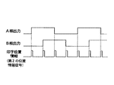
リニアエンコーダからは、図9に示すような90°位相がずれたA相出力とB相出力が得られ、これらの出力に基づいて印字位置ピッチを決定する位置情報信号が作られる。A1版,A0版といった大きな用紙への印字を目的とするプロッタでは、スケールは長尺となり、その分解能は限られたものとなる。従ってスケールの分解能以上の分解能を得るためには、A,B相出力を逓倍して位置情報信号を作ることが必要になる。例えば、図9に示すように、A,B相出力の立上がりおよび立下がりエッジを検出することにより、4逓倍した印字位置情報信号を生成することができる。これにより、スケールの分解能が180DPIであれば、720DPIの印字分解能を得ることができる。
【0004】
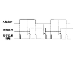
しかし、上述した従来のインクジェットプロッタにおける印字位置制御方式では、▲1▼エンコーダに誤差があった場合、図10に示したように4逓倍して得られる印字位置情報信号が等ピッチからずれて、画質が低下する、▲2▼分解能を任意に選択することはできず、またスケール分解能の4倍までしか分解能を上げることができない、という問題がある。
【0005】
そこで、本発明者は、印字分解能を任意に選択することができ、より高精度で高分解能の記録位置制御を可能にした記録装置を提案している(特開平9−254480号)。この記録装置は、エンコーダ出力のエッジ間隔を測定し、その時間データを予め定めた分割数で分割し、その分割時間毎にパルスを生成することにより、更に高い分解能を得ようとするものである。
【0006】
【発明が解決しようとする課題】
この発明は上述した従来の記録装置を更に改良し、高精度且つ高分解能の利点を維持しつつ、記録ヘッドの加減速時にも支障のない記録位置制御が行える記録装置を提供することを目的としている。
【0007】
【課題を解決するための手段】
本願の第1の発明は、ガイドに沿って駆動される記録ヘッドと、前記ガイドと平行配置されたスケールおよび前記記録ヘッドと一体に前記スケールに沿って駆動されて前記スケールの目盛りを読み取って位相の異なる複数のエンコーダ出力を出力するセンサからなるリニアエンコーダと、前記エンコーダ出力を処理して前記記録ヘッドの記録位置情報信号を発生する位置情報信号発生手段と、この位置情報信号発生手段から得られた位置情報信号と画像データとに基づいて前記記録ヘッドを駆動するヘッド駆動手段とを備えた記録装置において、前記位置情報信号発生手段は、前記リニアエンコーダの少なくともひとつのエンコーダ出力のエッジを検出して基準パルス信号を生成し、この基準パルス信号の間隔を測定して得られた時間測定データを予め定めた分割数で分割して分割時間データを求め、この分割時間データで示す時間を繰り返し計測して測定終了毎に補正信号を生成し、この補正信号と前記基準パルス信号とに基づいて第1の位置情報信号を出力する平均化手段と、前記複数のエンコーダ出力の各エッジを検出してその検出パルスを合成することにより得られた第2の位置情報信号を出力する逓倍手段と、前記平均化手段からの第1の位置情報信号と前記逓倍手段からの第2の位置情報信号のいずれか一方を選択して出力する選択手段と、前記記録ヘッドの移動速度が所定速度以上である場合には前記平均化手段からの第1の位置情報信号を記録位置情報信号として選択し、前記記録ヘッドの移動速度が所定速度よりも遅い場合には前記逓倍手段からの第2の位置情報信号を記録位置情報信号として選択するように前記選択手段を切り替え制御する切替制御手段とを備え、前記平均化手段は、前記基準パルス信号の間隔を測定して前記時間測定データを出力する時間測定カウンタを含み、前記切替制御手段は、連続する時間測定データ間の差分が前記分割時間データよりも小さい場合には前記第1の位置情報信号を記録位置情報信号として選択し、連続する時間測定データ間の差分が前記分割時間データ以上の場合には前記第2の位置情報信号を記録位置情報信号として選択するように前記選択手段を制御するものであることを特徴とする。
【0008】
この発明によれば、平均化手段における基準パルス間隔を示す時間測定データのオーバーフローの可能性が少ない記録ヘッドの高速移動時には、分解能を高い値で任意に選択できる平均化手段からの第1の位置情報信号を記録位置情報信号として選択し、時間測定データのオーバーフローの可能性が高い記録ヘッドの低速移動時には、逓倍手段からの第2の位置情報信号を記録位置情報信号として選択するようにしているので、記録ヘッドの移動スピードに拘わらず支障のない位置制御が可能になる。位置情報信号を切り替える記録ヘッドの速度としては、平均化回路での基準パルス間隔の測定に際して計数手段がオーバーフローする速度に多少のマージンを考慮して設定すればよい。
【0009】
また、本願の第2の発明は、ガイドに沿って駆動される記録ヘッドと、前記ガイドと平行配置されたスケールおよび前記記録ヘッドと一体に前記スケールに沿って駆動されて前記スケールの目盛りを読み取って位相の異なる複数のエンコーダ出力を出力するセンサからなるリニアエンコーダと、前記エンコーダ出力を処理して前記記録ヘッドの記録位置情報信号を発生する位置情報信号発生手段と、この位置情報信号発生手段から得られた位置情報信号と画像データとに基づいて前記記録ヘッドを駆動するヘッド駆動手段とを備えた記録装置において、前記位置情報信号発生手段が、前記リニアエンコーダの少なくともひとつのエンコーダ出力のエッジを検出して基準パルス信号を生成し、この基準パルス信号の間隔を測定して得られた時間測定データを予め定めた分割数で分割して分割時間データを求め、この分割時間データで示す時間を繰り返し計測して測定終了毎に補正信号を生成し、この補正信号と前記基準パルス信号とに基づいて第1の位置情報信号を出力する平均化手段と、前記複数のエンコーダ出力の各エッジを検出してその検出パルスを合成することにより得られた第2の位置情報信号を出力する逓倍手段と、前記平均化手段からの第1の位置情報信号と前記逓倍手段からの第2の位置情報信号のいずれか一方を選択して出力する選択手段と、前記記録ヘッドの移動加速度の絶対値が所定加速度以下である場合には前記平均化手段からの第1の位置情報信号を記録位置情報信号として選択し、前記記録ヘッドの移動加速度の絶対値が所定加速度よりも大きい場合には前記逓倍手段からの第2の位置情報信号を記録位置情報信号として選択するように前記選択手段を切り替え制御する切替制御手段とを備えたものであることを特徴としている。
【0010】
即ち、平均化手段で生成される第1の位置情報信号の出力タイミングは、過去に測定された基準パルス信号の間隔を示す時間測定データを分割して求められるので、記録ヘッドが加速中又は減速中で時間測定データの測定時とそれに基づく第1の位置情報信号の生成時との間で記録ヘッドの速度が異なっていた場合、基準パルス間に均等に位置情報信号を内挿することができない。また、測定時と内挿時とで大幅に速度が異なると、内挿すべきパルスが欠落したり、余計にパルスが挿入されたりする。一方、逓倍手段の出力は、現在の記録ヘッドの移動速度に従って変化するので、そのような問題は生じない。そこで、この発明では、記録ヘッドの移動加速度の絶対値が所定加速度以下である場合に限り平均化手段からの第1の位置情報信号を記録位置情報信号として選択し、その他の場合は、逓倍手段からの第2の位置情報信号を記録位置情報信号として選択することにより、加速時や減速時でも記録ヘッドの正確な位置制御を可能にしている。
【0011】
この発明において、前記切替制御手段は、好ましくは、連続する時間測定データ間の差分が前記分割時間データよりも小さい場合には前記第1の位置情報信号を記録位置情報信号として選択し、連続する時間測定データ間の差分が前記分割時間データ以上の場合には前記第2の位置情報信号を記録位置情報信号として選択するように前記選択手段を制御するものである。切替制御手段をそのように構成すると、加速時又は減速時に基準パルス間に内挿すべき位置情報信号が欠落したり、余分に位置情報信号を挿入してしまうという不具合は生じない。
【0012】
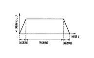
通常、記録ヘッドの速度カーブは加速領域、等速領域、減速領域からなり、実際の印字領域は等速領域であることが多い。このため、記録ヘッドが等速移動しているときには分解能が高い第1の記録位置情報を選択し、記録ヘッドが加速又は減速中のときには前記分解能は低くても、記録ヘッドの位置は正確に認識できる第2の記録位置情報を選択するようにしても良い。
【0013】
印字を行わない加速領域及び減速領域では、記録位置情報信号は単にカウント処理に供されるだけであるから、基準パルス信号の間に内挿されるパルスの数が正しければ問題はない。このため、平均化手段で基準パルス信号の間に正しい数のパルスが内挿される加速度の範囲、即ち連続する時間測定データ間の差分が前記分割時間データよりも小さい場合には、第1の位置情報信号を記録位置情報信号として選択し、それ以外の場合には第2の位置情報信号を記録位置情報信号として選択する。これにより、印字範囲だけでなく印字範囲外においても高分解能処理が可能になる。
【0014】
【発明の実施の形態】
以下、図面を参照して、この発明の実施例を説明する。
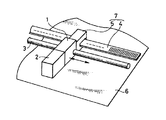
図1は、一実施例のインクジェットプロッタの要部構成であり、ラスタ走査を行うべく所定の配列でインクジェットノズルが設けられた印字ヘッドユニット2は、ガイドシャフト3に沿って駆動されるキャリッジ1に取り付けられて、印字記録すべき用紙6に対向配置される。ガイドシャフト3と平行に配置されたスケール4と、キャリッジ1に取り付けられてスケール4に沿って摺動してスケール目盛りを読み取るセンサ5とにより、リニアエンコーダ7が構成される。リニアエンコーダ7は、磁気式、光学式、静電容量式いずれでも良い。
【0015】
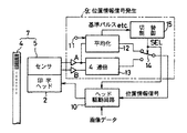
図2は、エンコーダ7の出力を用いて印字ヘッドユニット2の制御駆動を行う部分の構成を示している。但し、印字ヘッドユニット2の走査駆動制御回路は省略している。エンコーダ7のA,B相出力を用いて、位置情報信号発生回路9によって、スケール4の1ピッチ以下の印字位置情報信号を生成する。位置情報信号発生回路9から得られる位置情報信号は、画像データと共にヘッド駆動回路10に供給され、このヘッド駆動回路10により、インク吐出制御がなされる。
【0016】
位置情報信号発生回路9は、センサ5からのA,B相出力のうちA相出力から第1の位置情報信号を生成出力する平均化回路12、A,B相出力からその4逓倍の第2の位置情報信号を生成出力する4逓倍回路13、これらの出力を選択する選択回路14及び選択回路14を切替制御する切替制御回路15を備えて構成されている。平均化回路12は、A,B相出力のうちA相のみを導入してそのエッジを検出し、各エッジ間を分解能指令端子11を介して指定された分解能に基づいて分割することにより、指定された分解能に応じたパルスを内挿して第1の位置情報信号を得る。4逓倍回路13は、A,B相出力の各立ち上がり及び立ち下がりのエッジを検出して、各エッジ検出パルスを合成することにより第2の位置情報信号を得る。切替制御回路15は、平均化回路12からの情報に基づいて、印字ヘッド2の移動速度や移動加速度を検出し、その検出結果に基づいて選択回路14を切り替える。
【0017】
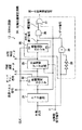
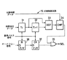
図3は、平均化回路12の具体的な構成である。図示のように、平均化回路12は、リニアエンコーダ7のA相出力である繰り返し出力パルスの立上がりエッジを検出して基準パルス信号を得るエッジ検出回路21と、このエッジ検出回路21により順次検出される基準パルス信号のパルス間隔を測定する第1の時間測定カウンタ22と、この時間測定カウンタ22により測定された時間データを前記基準パルス信号により順次サンプリングし、かつ分解能指令端子11からの指令により任意の整数nを選択して2n分割した分割時間データを生成する分割時間データ生成回路23と、この分割時間データ生成回路23により得られた分割時間データの時間を基準パルス信号の各周期内で繰り返し測定して測定終了毎に補正信号を生成し、この補正信号とエッジ検出回路21により得られる基準パルス信号とを時間軸上で合成して記録位置情報信号とする記録位置補正回路24とから構成される。
【0018】
時間測定カウンタ22は、エッジ検出回路21から順次得られる基準パルス信号によりクリアされてクロックCLKをカウントする動作を繰り返し、各サイクルでのピークカウント値を、A相出力の立上がりエッジ間の時間測定データとして順次出力する。分割時間データ生成回路23は、エッジ検出回路22により得られる基準パルス信号のパルス間隔を等ピッチで補間して高分解能の印字位置制御を行うための分解能設定部であって、時間測定カウンタ22により得られた二値データで表される時間データをエッジ検出回路22の出力によりサンプリングして取り込み、nビットシフトすることで2n分割した分割時間データを得る。即ち、分解能指令端子11から、ビットシフト量を指定することより、前のサイクルの測定時間を1/4,1/8,1/16等に分割した分割時間データを作る。
【0019】
記録位置補正回路24は、分割時間データ生成回路23により得られた分割時間データを測定する第2の時間測定カウンタ25を有する。この時間測定カウンタ25は例えば、分割時間データ生成回路23から得られる分割時間データがセットされ、これをクロックCLKによりダウンカウントして、0になるとカウント終了信号を出し、この終了信号により再度分割時間データがセットされてこれをダウンカウントして終了信号を出すという時間測定動作を繰り返す。
【0020】
第2の時間測定カウンタ25により得られるカウント終了信号はANDゲート26を通して取り出されて、補正信号とされる。ANDゲート26には、カウント終了信号のうち、各周期の最後の信号、即ち印字ヘッドが等速駆動された場合にエッジ検出回路21により得られる基準パルス信号と重なる部分を除くためのゲート信号が入力される。このゲート信号は、エンコーダ7のA相出力と、このA相出力を奇数段のインバータからなる反転遅延回路29によりτだけ遅延して反転した信号を入力とするNANDゲート28により作られる。
そして、ANDゲート26から得られる補正信号と、エッジ検出回路21により得られる基準パルス信号とを合成して第1の位置情報信号を得るORゲート27が設けられている。
【0021】
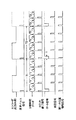
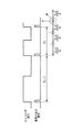
図4は、この様に構成された位置情報信号発生回路9の動作タイミングを示している。図示のように、エッジ検出回路21がエンコーダのA相出力の立上がりエッジを検出することにより、A相出力の1周期毎に基準パルス信号が得られる。順次得られる基準パルス信号の間隔を第1の時間測定カウンタ22により測定することにより、時間データT1,T2,…が得られる。等速駆動であれば、これらの時間データT1,T2,…は等しい。これらの時間データはそれぞれ次のサイクルで、分割時間データ生成回路23においてエッジ検出回路22の出力によりサンプリングされ、外部からの指令が4分割であれば、図示のように、4分割された時間データT1/4,T2/4…が作られる。なお、ここでは説明の簡単のため4分割としているが、平均化回路12での分割数は、4逓倍回路13の分割数よりも大きい、例えば8分割、16分割、32分割…のように設定される。
【0022】
これらの分割時間データを第2の時間測定カウンタ25で繰り返し測定する事により、基準パルス信号を4逓倍したカウント終了信号が得られる。これらのカウント終了信号は、NANDゲート28によりA相出力の立上がり部で作られる時間幅τのゲート信号により制御されるANDゲート26を通して、基準信号と重なるものが除かれて、図示のような補正信号が得られる。
【0023】
もし印字ヘッドが常に等速駆動されるとすれば、各周期のカウント終了信号の最後の信号は基準パルス信号と重なるから、ANDゲート28を用いることなく、全てのカウント終了信号を補正信号として用いても差し支えない。しかしこの実施例では、エンコーダの繰り返し出力パルスのあるサイクルで測定した時間に基づいて、次のサイクルで分割時間のカウントを行っているため、等速運動でない場合にはカウント終了信号の最終信号と基準パルス信号との間にズレが生じる。従ってANDゲート28により最終のカウント終了信号を除いて補正信号とすることが必要になる。そしてこの補正信号と基準パルス信号をORゲート27で時間軸上で合成することにより、補正された位置情報信号が得られる。
【0024】
この平均化回路12によれば、エンコーダのA相出力のみを利用して高分解能の位置情報信号を作っているから、エンコーダの読み取り誤差の影響を受けることなく、スケールの分解能以上の印字分解能を高精度に実現することができる。また、分割時間データは直前にサンプリングされた時間データをもとに作られるので、印字ヘッド2の移動速度が変動した場合でも補正信号は常に基準パルス信号の間に一定間隔で内挿されることになる。但し、分割時間データは、直前サイクルの時間データよりも前のサイクルでサンプリングされた時間データに基づいて生成することも可能であり、この場合でも時間差がそれ程大きくない場合には特に問題にならない。また分解能は外部から任意に設定することができ、例えばスケールの分解能が180DPIのときに、これを4逓倍した720DPIは勿論、1440DPI,2880DPIといった高分解能の印字記録を行うことができる。しかも、スケール自身を高分解能にする必要がなく、したがって長尺スケールを必要とする装置の場合にも、コスト上昇をもたらすことなく、優れた印字画質を得ることができる。
【0025】
ところで、図5に示すように、印字ヘッドユニット2は、加速域、等速域及び減速域をこの順に持つ移動速度カーブに沿って移動する。加速域及び減速域では、基準パルス信号の周期が大きく変化するので、平均化回路12によるパルスの内挿誤差が大きくなる。また、印字ヘッドユニット2の速度が遅いと時間測定カウンタ22がオーバーフローして正しい時間測定データが得られない。従って、平均化回路12からの位置情報信号による印字動作は、少なくとも等速域で行う必要がある。一方、印字範囲外では、単に記録位置情報信号をカウント動作するだけであるため、4逓倍回路13からの位置情報信号によるヘッドの移動制御を行えばよいが、基準パルスの間に正規の数の内挿パルスが内挿されるのであれば、加速域や減速域でも平均化回路12からの位置情報信号による動作が可能である。
【0026】
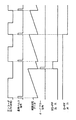
そこで、切替制御回路15を図6に示すように構成する。まず、時間測定カウンタ22から出力される時間測定データをレジスタ31,32に順次格納する。レジスタ31,32の出力は、それぞれ直前に測定された周期Tiのデータとその前に測定された周期Ti-1のデータである。これらのデータの差分の絶対値が差分回路33で算出され、その差分が比較回路34において所定値と比較される。この例では、所定値として分割時間データ生成部23からの分割時間データを用いている。即ち、図7に示すように、期間Ti-1の長さと期間Tiの長さの差が期間Ti-1で得られた時間測定データを分割して求められた分割時間データTi-1/4よりも大きい場合には、図中Pで示すように、周期Tiの中でパルスが1つ以上欠落してしまうからである。連続して導入される時間測定データの差が少なくなってきたら、即ち印字ヘッドユニット2が等速移動範囲であることが確認されたなら、ORゲート35を介して選択信号SELが“L”レベルになり、図2の選択回路14が平均化回路12からの第1の位置情報信号を選択するが、等速移動範囲であると確認されない場合には、選択信号SELが“H”レベルとなり、図2の選択回路14が4逓倍回路13からの第2の位置情報信号を選択する。
【0027】
また、時間測定カウンタ22がオーバーフローした場合には、時間測定カウンタ22からのオーバーフロー信号がRSフリップフロップ36のセット入力端子Sに入力され、図8に示すように、RSフリップフロップ36の出力が立ち上がり、その出力が次の基準パルス信号によってD型フリップフロップ37にラッチされる。このフリップフロップ37の出力がORゲート35の他方の入力として与えられる。この結果、印字ヘッドユニット2の停止時又は低速移動時には、時間測定カウンタ22がオーバーフローすることにより、選択信号SELが“H”レベルとなって、図2の選択回路14が4逓倍回路13からの第2の位置情報信号を選択する。
【0028】
なお、ヘッド駆動回路10は、選択回路14から与えられる記録位置情報信号に基づいて画像データを記録するため、印字ヘッドユニット2を駆動することになる。上記の例では、説明の簡単のため同じ分解能となっているが、実際には第2の位置情報信号よりも第1の位置情報信号の分解能の方が高い。このように第1の位置情報信号と第2の位置情報信号とで分解能が異なると、切替制御回路15からの選択信号SELをヘッド駆動回路10にも供給して、選択信号SELに応じた分解能によるヘッドの駆動処理を実行する必要がある。勿論、図示してはいないが、分解能指令端子11から入力される分解能データもヘッド駆動回路10に与えておく必要がある。
【0029】
このように、この実施例によれば、印字領域である等速域は勿論のこと、非印字領域である加減速領域においても、特定の条件を満たせば、平均化回路12による位置検出動作を行わせることができる。
【0030】
この発明は上記実施例に限られない。例えば実施例では、印字ヘッドユニット2の移動速度を平均化回路12の出力から検出したが、他の検出手段によって印字ヘッドユニット2の速度や加速度を検出するようにしてもよい。また、速度や加速度に基づき平均化手段の出力と逓倍手段の出力とを切り替える切替制御手段は、上述したようなハードウェアにより構成されたものの他に、ソフトウェアにより構成されたものでも良い。
また実施例ではインクジェット記録を説明したが、熱転写記録等他の方式の記録装置にも同様にこの発明を適用することができる。
【0031】
【発明の効果】
以上述べたようにこの発明によれば、記録ヘッドの移動速度や移動加速度に応じて最適なパルス内挿方式を選択することができ、高精度且つ高分解能の利点を維持しつつ、記録ヘッドの加減速時にも支障のない記録位置制御が可能な記録装置を提供することができる。
【図面の簡単な説明】
【図1】 この発明の一実施例に係るインクジェットプロッタの要部構成を示す斜視図である。
【図2】 同実施例のヘッドユニット駆動部の構成を示すブロック図である。
【図3】 同実施例の平均化回路の構成を示すブロック図である。
【図4】 同平均化回路の動作タイミング図である。
【図5】 同実施例における印字ヘッドユニットの速度カーブを示す図である。
【図6】 同実施例の切替制御回路の構成を示すブロック図である。
【図7】 同実施例の加速時の動作タイミング図である。
【図8】 同実施例の低速時の動作タイミング図である。
【図9】 従来の高分解能のための印字位置情報信号発生法を説明するためのタイミング図である。
【図10】 同印字位置情報信号発生法の問題点を説明するためのタイミング図である。
【符号の説明】
1…キャリッジ、2…印字ヘッドユニット、3…ガイドシャフト、4…スケール、5…センサ、6…シート、7…リニアエンコーダ、9…位置情報信号発生回路、10…ヘッド駆動回路、11…分解能指令端子、12…平均化回路、13…4逓倍回路、14…選択回路、15…切替制御回路、21…エッジ検出回路、22…第1の時間測定カウンタ、23…分割時間データ生成回路、24…記録位置補正回路、25…第2の時間測定カウンタ、26…ANDゲート、27…ORゲート、28…NANDゲート、29…反転遅延回路。[0001]
BACKGROUND OF THE INVENTION
The present invention relates to a recording apparatus such as an ink jet plotter that includes a linear encoder and performs position detection and recording position control of a recording head.
[0002]
[Prior art]
As an inkjet plotter, a linear encoder consisting of a print head driven along a guide shaft, a scale (timing fence) arranged in parallel with the guide shaft, and a sensor that is driven along the scale integrally with the print head and reads the scale graduation And a print position information signal is generated by the output of the linear encoder, and the print head is controlled and driven based on the position information signal and image data.
[0003]
From the linear encoder, phase A output and phase B output having a 90 ° phase shift as shown in FIG. 9 are obtained, and a position information signal for determining the print position pitch is generated based on these outputs. In plotters for printing on large paper such as A1 and A0 plates, the scale is long and its resolution is limited. Therefore, in order to obtain a resolution higher than the resolution of the scale, it is necessary to multiply the A and B phase outputs to create a position information signal. For example, as shown in FIG. 9, a print position information signal multiplied by 4 can be generated by detecting the rising and falling edges of the A and B phase outputs. Accordingly, if the resolution of the scale is 180 DPI, a printing resolution of 720 DPI can be obtained.
[0004]
However, in the printing position control method in the conventional inkjet plotter described above, (1) if there is an error in the encoder, the printing position information signal obtained by multiplying by 4 as shown in FIG. There is a problem that the image quality deteriorates, (2) the resolution cannot be arbitrarily selected, and the resolution can only be increased up to four times the scale resolution.
[0005]
In view of this, the present inventor has proposed a recording apparatus that can arbitrarily select a printing resolution and that enables high-precision and high-resolution recording position control (Japanese Patent Laid-Open No. 9-254480). This recording apparatus measures the edge interval of the encoder output, divides the time data by a predetermined number of divisions, and generates a pulse at each division time, thereby obtaining higher resolution. .
[0006]
[Problems to be solved by the invention]
An object of the present invention is to further improve the above-described conventional recording apparatus, and to provide a recording apparatus capable of controlling the recording position without any trouble even during acceleration / deceleration of the recording head while maintaining the advantages of high accuracy and high resolution. Yes.
[0007]
[Means for Solving the Problems]
According to a first aspect of the present invention, a recording head driven along a guide, a scale arranged in parallel with the guide, and a scale that is driven along the scale integrally with the recording head to read the scale of the scale A linear encoder comprising sensors for outputting a plurality of encoder outputs different from each other, a position information signal generating means for processing the encoder output to generate a recording position information signal of the recording head, and a position information signal generating means In the recording apparatus including the head driving unit that drives the recording head based on the positional information signal and the image data, the positional information signal generating unit detects an edge of at least one encoder output of the linear encoder. A reference pulse signal and time measurement data obtained by measuring the interval of the reference pulse signal. The division time data is obtained by dividing the data by a predetermined division number, the time indicated by the division time data is repeatedly measured, and a correction signal is generated at the end of each measurement. Based on the correction signal and the reference pulse signal, Averaging means for outputting the first position information signal, and multiplying means for outputting the second position information signal obtained by detecting each edge of the plurality of encoder outputs and synthesizing the detected pulses. Selection means for selecting and outputting one of the first position information signal from the averaging means and the second position information signal from the multiplication means, and the moving speed of the recording head is equal to or higher than a predetermined speed. In some cases, the first position information signal from the averaging means is selected as the recording position information signal. If the moving speed of the recording head is slower than a predetermined speed, the second position information signal from the multiplication means is selected. Switching control means for switching the selection means so as to select a signal as a recording position information signal, and the averaging means measures the interval of the reference pulse signal and outputs the time measurement data counter only contains the switching control means, when the difference between the time measurement data to be continuously is smaller than the split time data selects the first positional information signals as the recording position information signal, time successive measurements The selection means is controlled to select the second position information signal as a recording position information signal when the difference between the data is equal to or greater than the division time data .
[0008]
According to the present invention, the first position from the averaging means that can arbitrarily select a high resolution at the time of high-speed movement of the recording head when there is little possibility of overflow of time measurement data indicating the reference pulse interval in the averaging means. The information signal is selected as the recording position information signal, and the second position information signal from the multiplying means is selected as the recording position information signal when the recording head is likely to overflow the time measurement data at a low speed. Therefore, position control can be performed without any problem regardless of the moving speed of the recording head. The speed of the recording head for switching the position information signal may be set in consideration of some margin in the speed at which the counting means overflows when measuring the reference pulse interval in the averaging circuit.
[0009]
Further, the second invention of the present application reads the scale of the scale by being driven along the scale integrally with the recording head driven along the guide, the scale arranged in parallel with the guide, and the recording head. A linear encoder comprising sensors for outputting a plurality of encoder outputs having different phases, a position information signal generating means for processing the encoder output to generate a recording position information signal of the recording head, and a position information signal generating means In a recording apparatus including a head driving unit that drives the recording head based on the obtained positional information signal and image data, the positional information signal generating unit detects an edge of at least one encoder output of the linear encoder. The time obtained by detecting and generating a reference pulse signal and measuring the interval of this reference pulse signal The fixed data is divided by a predetermined number of divisions to obtain division time data, and the time indicated by the division time data is repeatedly measured to generate a correction signal at every measurement end, and the correction signal and the reference pulse signal are An averaging means for outputting a first position information signal based on the signal, and a multiplying means for outputting a second position information signal obtained by detecting each edge of the plurality of encoder outputs and combining the detected pulses. Selection means for selecting and outputting one of the first position information signal from the averaging means and the second position information signal from the multiplication means, and the absolute value of the moving acceleration of the recording head is When the acceleration is equal to or less than a predetermined acceleration, the first position information signal from the averaging means is selected as a recording position information signal, and the absolute value of the moving acceleration of the recording head is larger than the predetermined acceleration. It is characterized in that with a switching control means for controlling switching of said selection means to select the second position information signal from the multiplying unit as the recording position information signal.
[0010]
That is, the output timing of the first position information signal generated by the averaging means is obtained by dividing the time measurement data indicating the interval of the reference pulse signal measured in the past, so that the recording head is accelerating or decelerating. In particular, when the speed of the recording head is different between the time measurement data measurement time and the generation of the first position information signal based on the time measurement data, the position information signal cannot be evenly interpolated between the reference pulses. . In addition, if the speed is significantly different between the time of measurement and the time of interpolation, a pulse to be interpolated is lost or an extra pulse is inserted. On the other hand, since the output of the multiplication means changes according to the current moving speed of the recording head, such a problem does not occur. Therefore, in the present invention, the first position information signal from the averaging means is selected as the recording position information signal only when the absolute value of the moving acceleration of the recording head is equal to or less than the predetermined acceleration, and in other cases, the multiplying means. By selecting the second position information signal from as the recording position information signal, it is possible to accurately control the position of the recording head even during acceleration or deceleration.
[0011]
In the present invention, the switching control means preferably selects the first position information signal as a recording position information signal when the difference between successive time measurement data is smaller than the divided time data, and continues. When the difference between the time measurement data is greater than or equal to the divided time data, the selection means is controlled to select the second position information signal as the recording position information signal. If the switching control means is configured in such a manner, there is no problem that a position information signal to be interpolated between reference pulses at the time of acceleration or deceleration is lost or an extra position information signal is inserted.
[0012]
Usually, the velocity curve of the recording head is composed of an acceleration region, a constant velocity region, and a deceleration region, and the actual printing region is often a constant velocity region. Therefore, the first recording position information with high resolution is selected when the recording head is moving at a constant speed, and the position of the recording head is accurately recognized even when the resolution is low when the recording head is accelerating or decelerating. The second recording position information that can be selected may be selected.
[0013]
In the acceleration area and the deceleration area where printing is not performed, the recording position information signal is merely used for the counting process, so that there is no problem as long as the number of pulses inserted between the reference pulse signals is correct. For this reason, if the averaging means has an acceleration range in which the correct number of pulses are interpolated between the reference pulse signals, that is, if the difference between successive time measurement data is smaller than the divided time data, the first position The information signal is selected as the recording position information signal, and in other cases, the second position information signal is selected as the recording position information signal. This enables high-resolution processing not only in the print range but also outside the print range.
[0014]
DETAILED DESCRIPTION OF THE INVENTION
Embodiments of the present invention will be described below with reference to the drawings.
FIG. 1 shows a configuration of a main part of an ink jet plotter according to an embodiment. A
[0015]
FIG. 2 shows a configuration of a portion that performs control drive of the
[0016]
The position information signal generation circuit 9 generates and outputs a first position information signal from the A phase output among the A and B phase outputs from the
[0017]
FIG. 3 shows a specific configuration of the averaging
[0018]
The
[0019]
The recording position correction circuit 24 includes a second
[0020]
The count end signal obtained by the second
An OR
[0021]
FIG. 4 shows the operation timing of the position information signal generating circuit 9 configured as described above. As shown in the figure, the
[0022]
By repeatedly measuring these divided time data with the second
[0023]
If the print head is always driven at a constant speed, the last signal of the count end signal in each cycle overlaps the reference pulse signal, so that all the count end signals are used as correction signals without using the AND
[0024]
According to the averaging
[0025]
Incidentally, as shown in FIG. 5, the
[0026]
Therefore, the switching
[0027]
When the
[0028]
The
[0029]
As described above, according to this embodiment, the position detection operation by the averaging
[0030]
The present invention is not limited to the above embodiment. For example, in the embodiment, the moving speed of the
In the embodiments, ink jet recording has been described. However, the present invention can be similarly applied to recording apparatuses of other systems such as thermal transfer recording.
[0031]
【The invention's effect】
As described above, according to the present invention, the optimum pulse interpolation method can be selected according to the moving speed and moving acceleration of the recording head, and while maintaining the advantages of high accuracy and high resolution, It is possible to provide a recording apparatus capable of controlling the recording position without any trouble during acceleration / deceleration.
[Brief description of the drawings]
FIG. 1 is a perspective view showing a configuration of a main part of an ink jet plotter according to an embodiment of the present invention.
FIG. 2 is a block diagram illustrating a configuration of a head unit driving unit according to the embodiment.
FIG. 3 is a block diagram showing a configuration of an averaging circuit of the same embodiment.
FIG. 4 is an operation timing chart of the averaging circuit.
FIG. 5 is a diagram showing a velocity curve of the print head unit in the same embodiment.
FIG. 6 is a block diagram showing a configuration of a switching control circuit of the same embodiment.
FIG. 7 is an operation timing chart during acceleration according to the embodiment.
FIG. 8 is an operation timing chart at the low speed of the embodiment.
FIG. 9 is a timing diagram for explaining a conventional printing position information signal generation method for high resolution.
FIG. 10 is a timing chart for explaining problems of the printing position information signal generation method.
[Explanation of symbols]
DESCRIPTION OF
Claims (5)
前記ガイドと平行配置されたスケールおよび前記記録ヘッドと一体に前記スケールに沿って駆動されて前記スケールの目盛りを読み取って位相の異なる複数のエンコーダ出力を出力するセンサからなるリニアエンコーダと、
前記エンコーダ出力を処理して前記記録ヘッドの記録位置情報信号を発生する位置情報信号発生手段と、
この位置情報信号発生手段から得られた位置情報信号と画像データとに基づいて前記記録ヘッドを駆動するヘッド駆動手段と
を備えた記録装置において、
前記位置情報信号発生手段は、
前記リニアエンコーダの少なくともひとつのエンコーダ出力のエッジを検出して基準パルス信号を生成し、この基準パルス信号の間隔を測定して得られた時間測定データを予め定めた分割数で分割して分割時間データを求め、この分割時間データで示す時間を繰り返し計測して測定終了毎に補正信号を生成し、この補正信号と前記基準パルス信号とに基づいて第1の位置情報信号を出力する平均化手段と、
前記複数のエンコーダ出力の各エッジを検出してその検出パルスを合成することにより得られた第2の位置情報信号を出力する逓倍手段と、
前記平均化手段からの第1の位置情報信号と前記逓倍手段からの第2の位置情報信号のいずれか一方を選択して出力する選択手段と、
前記記録ヘッドの移動速度が所定速度以上である場合には前記平均化手段からの第1の位置情報信号を記録位置情報信号として選択し、前記記録ヘッドの移動速度が所定速度よりも遅い場合には前記逓倍手段からの第2の位置情報信号を記録位置情報信号として選択するように前記選択手段を切り替え制御する切替制御手段とを備え、
前記平均化手段は、前記基準パルス信号の間隔を測定して前記時間測定データを出力する時間測定カウンタを含み、
前記切替制御手段は、連続する時間測定データ間の差分が前記分割時間データよりも小さい場合には前記第1の位置情報信号を記録位置情報信号として選択し、連続する時間測定データ間の差分が前記分割時間データ以上の場合には前記第2の位置情報信号を記録位置情報信号として選択するように前記選択手段を制御する
ものであることを特徴とする記録装置。A recording head driven along a guide;
A linear encoder comprising a scale arranged in parallel with the guide and a sensor that is driven along the scale integrally with the recording head to read scales of the scale and output a plurality of encoder outputs having different phases;
Position information signal generating means for processing the encoder output to generate a recording position information signal of the recording head;
In a recording apparatus comprising: a head driving unit that drives the recording head based on a positional information signal and image data obtained from the positional information signal generating unit;
The position information signal generating means includes
A reference pulse signal is generated by detecting an edge of at least one encoder output of the linear encoder, and time measurement data obtained by measuring an interval of the reference pulse signal is divided by a predetermined number of divisions. An averaging means for obtaining data, repeatedly measuring the time indicated by the divided time data, generating a correction signal at every measurement end, and outputting a first position information signal based on the correction signal and the reference pulse signal When,
Multiplication means for outputting a second position information signal obtained by detecting each edge of the plurality of encoder outputs and synthesizing the detection pulses;
Selecting means for selecting and outputting one of the first position information signal from the averaging means and the second position information signal from the multiplication means;
When the moving speed of the recording head is equal to or higher than a predetermined speed, the first position information signal from the averaging means is selected as the recording position information signal, and the moving speed of the recording head is slower than the predetermined speed. Comprises switching control means for switching the selection means so as to select the second position information signal from the multiplication means as a recording position information signal,
It said averaging means, seen including a time measurement counter for outputting the time measured data by measuring the interval of the reference pulse signal,
The switching control means selects the first position information signal as a recording position information signal when the difference between successive time measurement data is smaller than the divided time data, and the difference between successive time measurement data is The recording apparatus according to claim 1 , wherein the selection unit is controlled so as to select the second position information signal as a recording position information signal when the divided time data or more .
前記ガイドと平行配置されたスケールおよび前記記録ヘッドと一体に前記スケールに沿って駆動されて前記スケールの目盛りを読み取って位相の異なる複数のエンコーダ出力を出力するセンサからなるリニアエンコーダと、
前記エンコーダ出力を処理して前記記録ヘッドの記録位置情報信号を発生する位置情報信号発生手段と、
この位置情報信号発生手段から得られた位置情報信号と画像データとに基づいて前記記録ヘッドを駆動するヘッド駆動手段と
を備えた記録装置において、
前記位置情報信号発生手段は、
前記リニアエンコーダの少なくともひとつのエンコーダ出力のエッジを検出して基準パルス信号を生成し、この基準パルス信号の間隔を測定して得られた時間測定データを予め定めた分割数で分割して分割時間データを求め、この分割時間データで示す時間を繰り返し計測して測定終了毎に補正信号を生成し、この補正信号と前記基準パルス信号とに基づいて第1の位置情報信号を出力する平均化手段と、
前記複数のエンコーダ出力の各エッジを検出してその検出パルスを合成することにより得られた第2の位置情報信号を出力する逓倍手段と、
前記平均化手段からの第1の位置情報信号と前記逓倍手段からの第2の位置情報信号のいずれか一方を選択して出力する選択手段と、
前記記録ヘッドの移動加速度の絶対値が所定加速度以下である場合には前記平均化手段からの第1の位置情報信号を記録位置情報信号として選択し、前記記録ヘッドの移動加速度の絶対値が所定加速度よりも大きい場合には前記逓倍手段からの第2の位置情報信号を記録位置情報信号として選択するように前記選択手段を切り替え制御する切替制御手段と
を備えたものであることを特徴とする記録装置。A recording head driven along a guide;
A linear encoder comprising a scale arranged in parallel with the guide and a sensor that is driven along the scale integrally with the recording head to read scales of the scale and output a plurality of encoder outputs having different phases;
Position information signal generating means for processing the encoder output to generate a recording position information signal of the recording head;
In a recording apparatus comprising: a head driving unit that drives the recording head based on a positional information signal and image data obtained from the positional information signal generating unit;
The position information signal generating means includes
A reference pulse signal is generated by detecting an edge of at least one encoder output of the linear encoder, and time measurement data obtained by measuring an interval of the reference pulse signal is divided by a predetermined number of divisions. An averaging means for obtaining data, repeatedly measuring the time indicated by the divided time data, generating a correction signal at every measurement end, and outputting a first position information signal based on the correction signal and the reference pulse signal When,
Multiplication means for outputting a second position information signal obtained by detecting each edge of the plurality of encoder outputs and synthesizing the detection pulses;
Selecting means for selecting and outputting one of the first position information signal from the averaging means and the second position information signal from the multiplication means;
If the absolute value of the moving acceleration of the recording head is less than or equal to a predetermined acceleration, the first position information signal from the averaging means is selected as the recording position information signal, and the absolute value of the moving acceleration of the recording head is predetermined. Switching control means for switching the selection means so as to select the second position information signal from the multiplication means as a recording position information signal when the acceleration is greater than the acceleration means. Recording device.
Priority Applications (3)
| Application Number | Priority Date | Filing Date | Title |
|---|---|---|---|
| JP12089598A JP3645708B2 (en) | 1998-04-30 | 1998-04-30 | Recording device |
| US09/301,166 US6042281A (en) | 1998-04-30 | 1999-04-28 | Printing apparatus |
| DE19919805A DE19919805C2 (en) | 1998-04-30 | 1999-04-30 | printing device |
Applications Claiming Priority (1)
| Application Number | Priority Date | Filing Date | Title |
|---|---|---|---|
| JP12089598A JP3645708B2 (en) | 1998-04-30 | 1998-04-30 | Recording device |
Related Child Applications (1)
| Application Number | Title | Priority Date | Filing Date |
|---|---|---|---|
| JP2004329111A Division JP4160949B2 (en) | 2004-11-12 | 2004-11-12 | Recording device |
Publications (2)
| Publication Number | Publication Date |
|---|---|
| JPH11316136A JPH11316136A (en) | 1999-11-16 |
| JP3645708B2 true JP3645708B2 (en) | 2005-05-11 |
Family
ID=14797660
Family Applications (1)
| Application Number | Title | Priority Date | Filing Date |
|---|---|---|---|
| JP12089598A Expired - Fee Related JP3645708B2 (en) | 1998-04-30 | 1998-04-30 | Recording device |
Country Status (3)
| Country | Link |
|---|---|
| US (1) | US6042281A (en) |
| JP (1) | JP3645708B2 (en) |
| DE (1) | DE19919805C2 (en) |
Families Citing this family (11)
| Publication number | Priority date | Publication date | Assignee | Title |
|---|---|---|---|---|
| JP3501654B2 (en) * | 1998-07-16 | 2004-03-02 | キヤノン株式会社 | Recording device |
| JP2001341372A (en) * | 2000-06-06 | 2001-12-11 | Mimaki Engineering Co Ltd | Ink jet plotter and its using method |
| US6523925B1 (en) * | 2001-10-30 | 2003-02-25 | Hewlett-Packard Company | Media leading edge sensor |
| US7190145B2 (en) * | 2002-01-16 | 2007-03-13 | Ballard Power Systems Corporation | Method and apparatus for improving speed measurement quality in multi-pole machines |
| US7059698B1 (en) | 2002-10-04 | 2006-06-13 | Lexmark International, Inc. | Method of altering an effective print resolution of an ink jet printer |
| US6951335B2 (en) | 2002-10-29 | 2005-10-04 | Hewlett-Packard Development Company, L.P. | Reciprocating linear encoder |
| DE10300918B4 (en) * | 2003-01-13 | 2014-11-06 | Robert Bosch Gmbh | Apparatus and method for detecting the relative movement of two relatively movable machine parts |
| GB2434563A (en) * | 2004-11-26 | 2007-08-01 | Marc Jonathan Brown | Marking system with integrated linearity synchronisation |
| JP4725322B2 (en) * | 2005-12-28 | 2011-07-13 | ブラザー工業株式会社 | Image forming apparatus |
| JP5551669B2 (en) * | 2011-09-30 | 2014-07-16 | 富士フイルム株式会社 | Inkjet recording apparatus and method |
| JP7258609B2 (en) * | 2019-03-15 | 2023-04-17 | ミネベアミツミ株式会社 | Position detector |
Family Cites Families (7)
| Publication number | Priority date | Publication date | Assignee | Title |
|---|---|---|---|---|
| US4709247A (en) * | 1986-12-22 | 1987-11-24 | Eastman Kodak Company | High resolution, print/cartridge ink, jet printer |
| US4709248A (en) * | 1986-12-22 | 1987-11-24 | Eastman Kodak Company | Transverse printing control system for multiple print/cartridge printer |
| US5288157A (en) * | 1990-05-15 | 1994-02-22 | Seiko Epson Corporation | Printing control system having means to correct flight time |
| US5433541A (en) * | 1992-12-15 | 1995-07-18 | Nec Corporation | Control device for controlling movement of a printing head carriage and control method for controlling the same |
| US5411340A (en) * | 1993-09-17 | 1995-05-02 | Hewlett-Packard Company | "Milepost" single-channel encoder, scale, and method, for midscan turn around in a scanning-head printer or reader |
| JPH09202014A (en) * | 1996-01-24 | 1997-08-05 | Brother Ind Ltd | Printer |
| JP3582750B2 (en) * | 1996-03-25 | 2004-10-27 | 武藤工業株式会社 | Recording device |
-
1998
- 1998-04-30 JP JP12089598A patent/JP3645708B2/en not_active Expired - Fee Related
-
1999
- 1999-04-28 US US09/301,166 patent/US6042281A/en not_active Expired - Lifetime
- 1999-04-30 DE DE19919805A patent/DE19919805C2/en not_active Expired - Lifetime
Also Published As
| Publication number | Publication date |
|---|---|
| DE19919805C2 (en) | 2003-03-20 |
| US6042281A (en) | 2000-03-28 |
| JPH11316136A (en) | 1999-11-16 |
| DE19919805A1 (en) | 1999-11-04 |
Similar Documents
| Publication | Publication Date | Title |
|---|---|---|
| JP3645708B2 (en) | Recording device | |
| US4147967A (en) | Apparatus and method for controlling the velocity of a moveable member | |
| US4602882A (en) | Control system of serial printer | |
| JP2002034274A (en) | Digital encoder control method | |
| US6302506B1 (en) | Apparatus and method for correcting carriage velocity induced ink drop positional errors | |
| US4167014A (en) | Circuitry for perfecting ink drop printing at varying carrier velocity | |
| JPH11277808A (en) | Timing pulse generator and printer | |
| JP4160949B2 (en) | Recording device | |
| US5331680A (en) | Position detecting apparatus | |
| US7221114B2 (en) | Conveyance control apparatus and image forming apparatus | |
| JP3582750B2 (en) | Recording device | |
| US6654508B1 (en) | Correction and interpolation of position encoders | |
| US4167013A (en) | Circuitry for perfecting ink drop printing at nonlinear carrier velocity | |
| JPH09136465A (en) | Timing pulse generator | |
| GB1587811A (en) | Ink jet pirnters | |
| JP3609269B2 (en) | Image forming method and apparatus | |
| JPH0228163B2 (en) | KUDORYOKENSHUTSUSOCHI | |
| JPH10315559A (en) | Print head position control device | |
| JP2001146054A (en) | Recording device | |
| JP2007076216A (en) | Inkjet recording device | |
| JPH0655795A (en) | Printing signal generation method and device in serial printer | |
| JP3513400B2 (en) | Serial recording device and serial recording method | |
| JP4366066B2 (en) | Recording apparatus control method and recording apparatus | |
| JP4115191B2 (en) | Motor control device and control method | |
| JPH0684974B2 (en) | Travel time detection circuit |
Legal Events
| Date | Code | Title | Description |
|---|---|---|---|
| A977 | Report on retrieval |
Free format text: JAPANESE INTERMEDIATE CODE: A971007 Effective date: 20040601 |
|
| A131 | Notification of reasons for refusal |
Free format text: JAPANESE INTERMEDIATE CODE: A131 Effective date: 20040615 |
|
| A521 | Request for written amendment filed |
Free format text: JAPANESE INTERMEDIATE CODE: A523 Effective date: 20040811 |
|
| A02 | Decision of refusal |
Free format text: JAPANESE INTERMEDIATE CODE: A02 Effective date: 20040914 |
|
| A521 | Request for written amendment filed |
Free format text: JAPANESE INTERMEDIATE CODE: A523 Effective date: 20041112 |
|
| A911 | Transfer to examiner for re-examination before appeal (zenchi) |
Free format text: JAPANESE INTERMEDIATE CODE: A911 Effective date: 20041124 |
|
| TRDD | Decision of grant or rejection written | ||
| A01 | Written decision to grant a patent or to grant a registration (utility model) |
Free format text: JAPANESE INTERMEDIATE CODE: A01 Effective date: 20050111 |
|
| A61 | First payment of annual fees (during grant procedure) |
Free format text: JAPANESE INTERMEDIATE CODE: A61 Effective date: 20050204 |
|
| R150 | Certificate of patent or registration of utility model |
Free format text: JAPANESE INTERMEDIATE CODE: R150 |
|
| S111 | Request for change of ownership or part of ownership |
Free format text: JAPANESE INTERMEDIATE CODE: R313111 |
|
| FPAY | Renewal fee payment (event date is renewal date of database) |
Free format text: PAYMENT UNTIL: 20080210 Year of fee payment: 3 |
|
| R350 | Written notification of registration of transfer |
Free format text: JAPANESE INTERMEDIATE CODE: R350 |
|
| FPAY | Renewal fee payment (event date is renewal date of database) |
Free format text: PAYMENT UNTIL: 20080210 Year of fee payment: 3 |
|
| FPAY | Renewal fee payment (event date is renewal date of database) |
Free format text: PAYMENT UNTIL: 20090210 Year of fee payment: 4 |
|
| FPAY | Renewal fee payment (event date is renewal date of database) |
Free format text: PAYMENT UNTIL: 20100210 Year of fee payment: 5 |
|
| FPAY | Renewal fee payment (event date is renewal date of database) |
Free format text: PAYMENT UNTIL: 20110210 Year of fee payment: 6 |
|
| FPAY | Renewal fee payment (event date is renewal date of database) |
Free format text: PAYMENT UNTIL: 20120210 Year of fee payment: 7 |
|
| FPAY | Renewal fee payment (event date is renewal date of database) |
Free format text: PAYMENT UNTIL: 20120210 Year of fee payment: 7 |
|
| S531 | Written request for registration of change of domicile |
Free format text: JAPANESE INTERMEDIATE CODE: R313531 |
|
| R350 | Written notification of registration of transfer |
Free format text: JAPANESE INTERMEDIATE CODE: R350 |
|
| FPAY | Renewal fee payment (event date is renewal date of database) |
Free format text: PAYMENT UNTIL: 20130210 Year of fee payment: 8 |
|
| FPAY | Renewal fee payment (event date is renewal date of database) |
Free format text: PAYMENT UNTIL: 20140210 Year of fee payment: 9 |
|
| R250 | Receipt of annual fees |
Free format text: JAPANESE INTERMEDIATE CODE: R250 |
|
| LAPS | Cancellation because of no payment of annual fees |